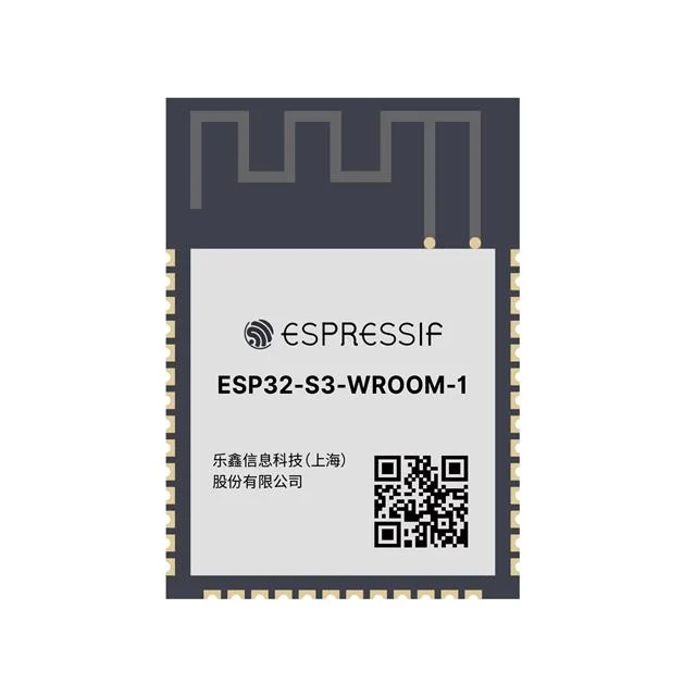
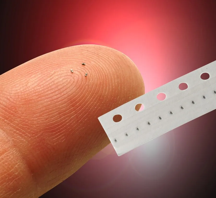
As part of running the ADSBee project, I’ve found myself with the less than exciting job of counting tens of thousands of components for inventory and consignment purposes, ranging from tiny 0201 resistors and caps to large LGA modules like the ESP32 S3.
Usually, counting these components is done by figuring out the pitch of the tape (number of components per 4mm feeder hole), and then measuring out the length of the tape by hand using a ruler or yardstick. This is relativley quick for small cut tapes, but can quickly become untenable for partial reels of components, where it can be easy to lose track of the exact hole you last had at the end of the measuring tape if you need to measure multiple lengths at a time.
There are a number of existing solutions to this problem, which generally rely on some sort of device that counts the holes in the tap for you, and multiplies it by the part pitch to give you a component count. I had backed one of these devices, the BeanCounter, on CrowdSupply, but sadly my order never shipped (I think I placed it after the initial batch was sold, and no subsequent batches were ever made). After more than a year of waiting for my BeanCounter, and counting thousands of parts by hand, I got tired of waiting for a solution to appear and decided to put something together myself.
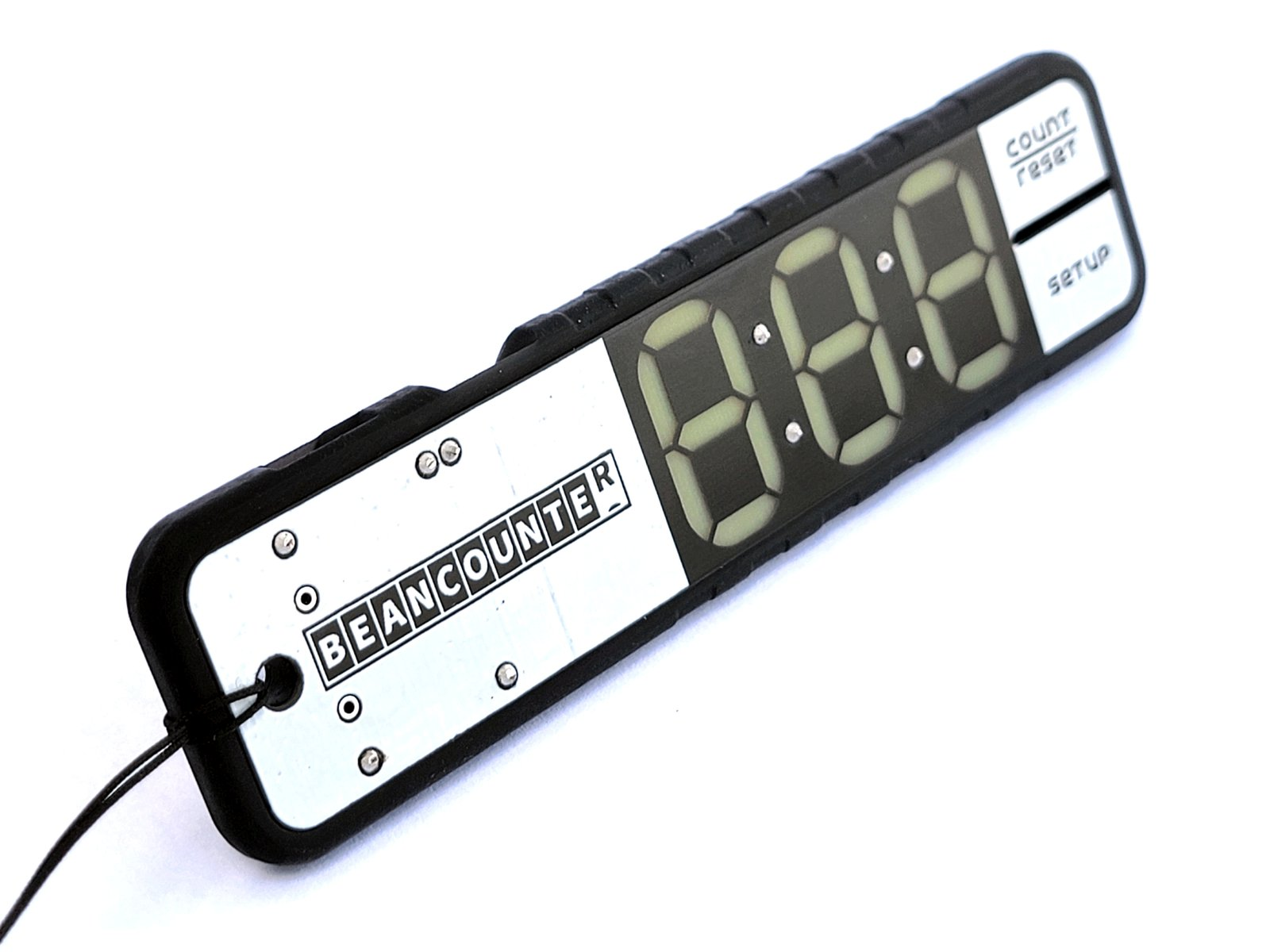
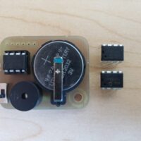
BeanCounter’s main draw was that it was a small and relatively portable device that could do the task of much larger desktop-mounted machines. It used a few photo gates to count holes on paper tape as it was pulled through, and had a very sleek dual PCB design with a counter display that was diffused through a layer of FR4. The whole thing runs on a coin cell battery, and is small and light enough to put in your pocket.
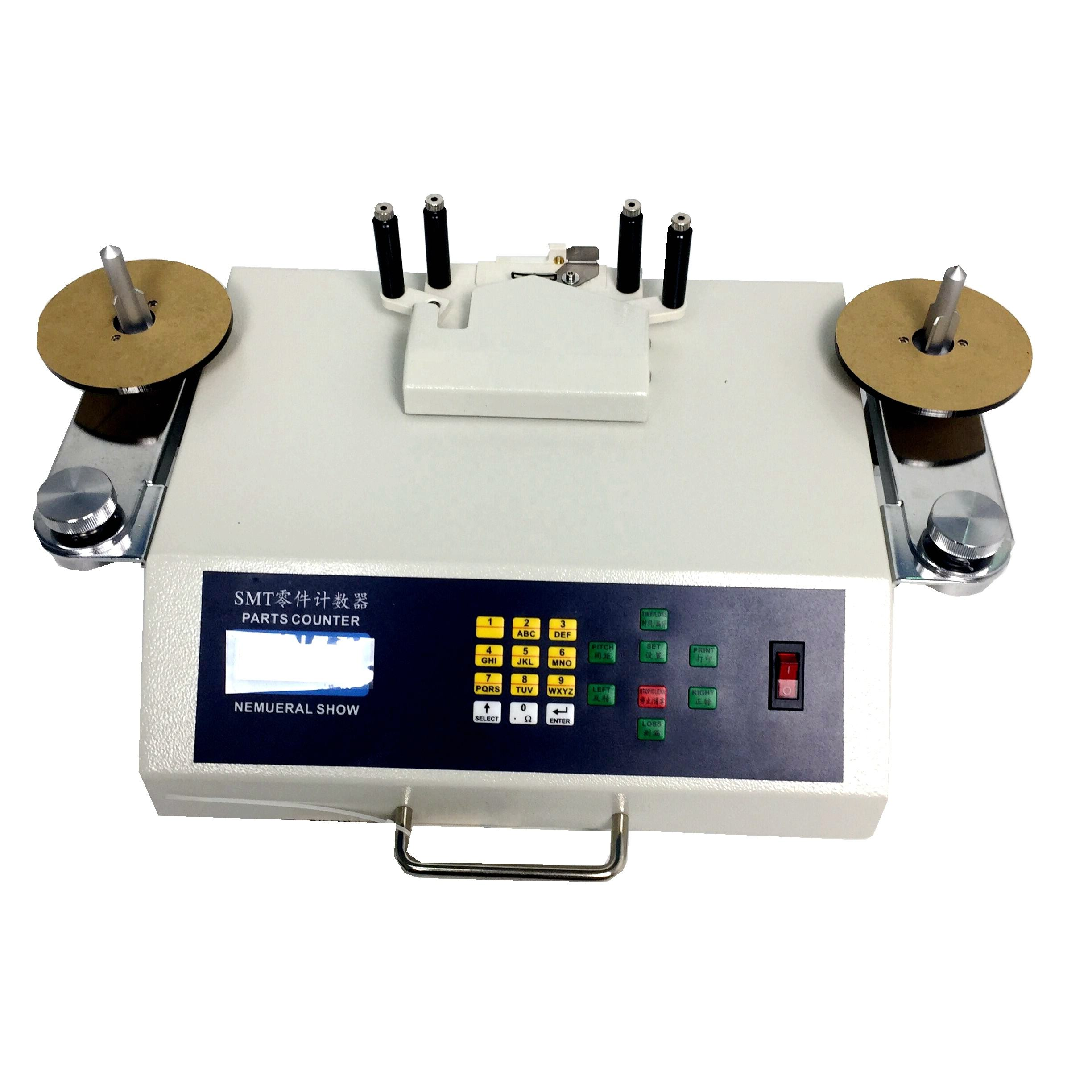
By comparison, the SMT counter machines used in factory applications are expensive and relatively heavy, and often have automatic spools that can drive the components between two reels while counting the holes as they go by. These cost hundreds of dollars each, and everyone knows that any benchtop shaped piece of real estate in my lab has already been completely claimed by expensive equipment or various piles of mission critical garbage. For an infrequently used tool like an SMT component counter, dedicating valuable benchtop real estate wasn’t in the cards. So, it was time to build something small (and cheap), with some of the features of BeanCounter, and some extensions that would make it better for my application.
There were a few key disadvantages to the BeanCounter, other than its lack of availability. The BeanCounter was optimized for 8mm wide paper tape, which can be pulled through the device manually. The slot in the device that captures the paper tape is only sized for 8mm wide tape, so wider tapes with other components I use (like ESP32 modules), or tape with deep pockets (for connectors or electrolytic capacitors) simply wouldn’t fit. I haven’t used a BeanCounter myself, but I also imagine that it might struggle with different tape types, like transparent plastic tape that is often used for larger ceramic capacitors (although those tapes might be too thick to fit through the tape slot anyhow). Any device that I built would need to accommodate all tape colors and material types (clear plastic / black plastic / paper), all tape widths (8mm to biiiiig), and all pocket depths. After some head scratching and a few days of impulsive CAD modeling, I came up with a workable solution!
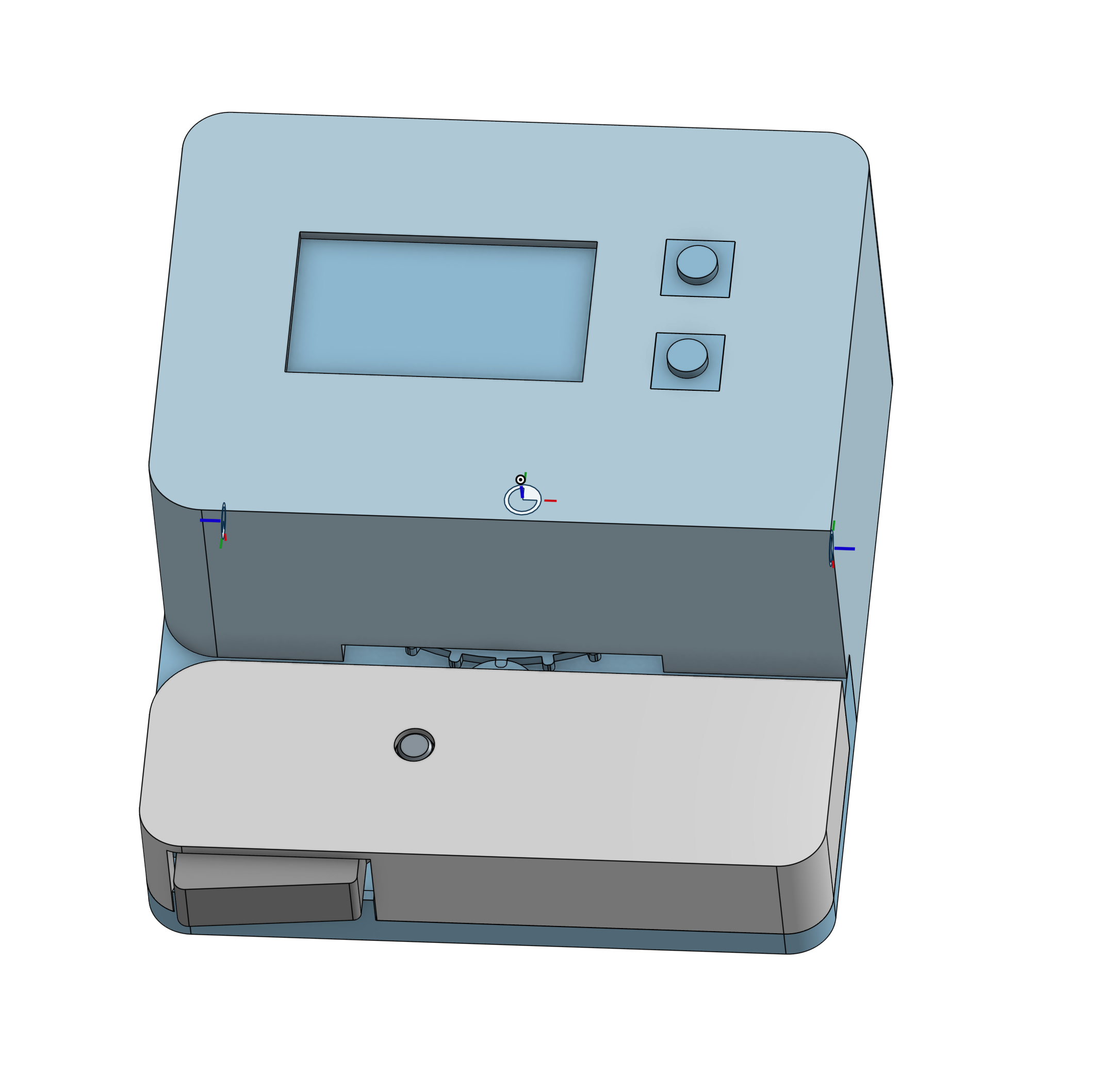
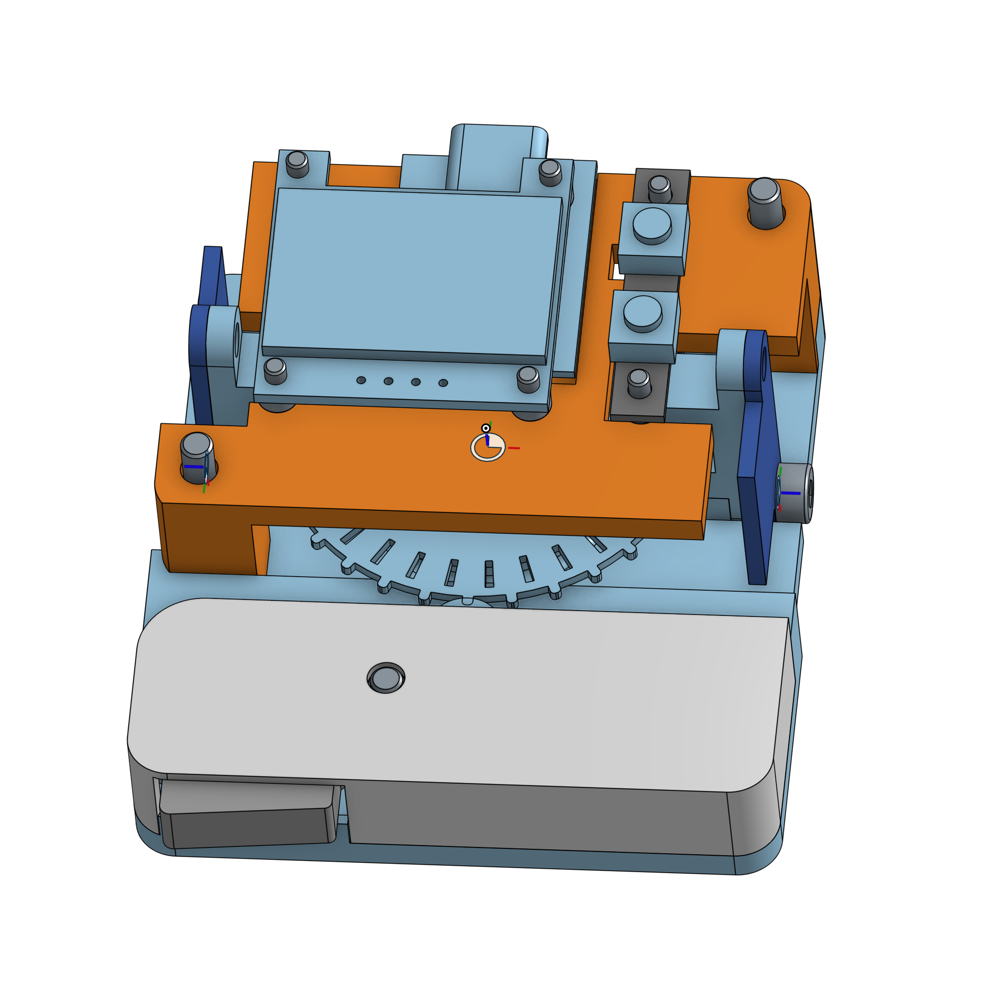
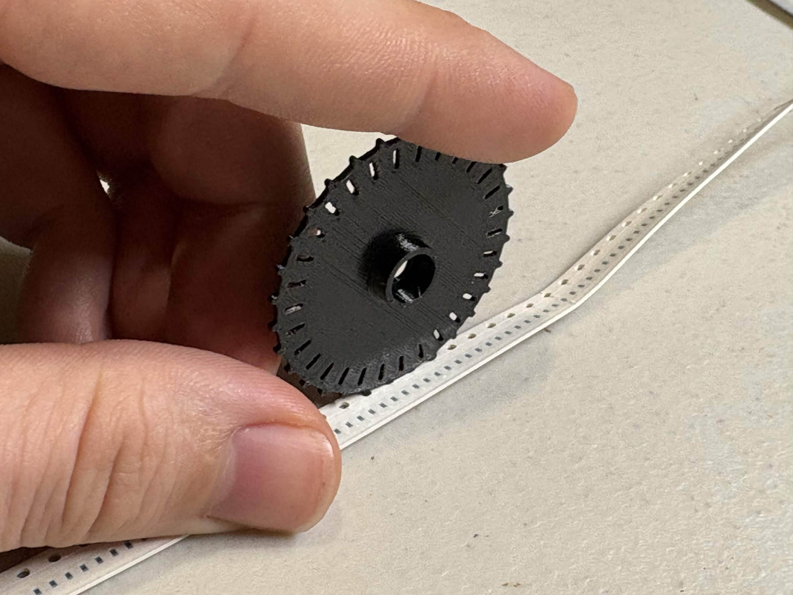
The Dotterboard uses a 3D printed sprocket wheel to engage with an SMT component tape and count the holes. Each hole grabs a single tooth on the sprocket wheel, which has a corresponding slot closer to the center of the wheel. Reading slots with photo gates inside the dotterboard allows the slots to be counted, and reading with two photo gates that are set 90 degrees out of phase (in quadrature) allows the direction of travel to be discerned as the slots are counted.
I was pleasantly surprised at how easy it was to 3D print a sprocket wheel to engage with the SMT tape holes. I swapped a 0.2mm nozzle onto my printer to get better resolution, and printed at a relatively low layer height with PETG.
The sprocket wheel is held onto the component tape from the opposite side using a spring-loaded idler. The idler includes a release lever that can be used to disengage the sprocket wheel from the tape in the middle of a count, and the spring loaded bearing makes a very satisfying “takkatakkatakkatakka” sound as the SMT tape is pulled through the counter, providing a helpful auditory cue that the tape is properly engaged with the sprocket wheel.
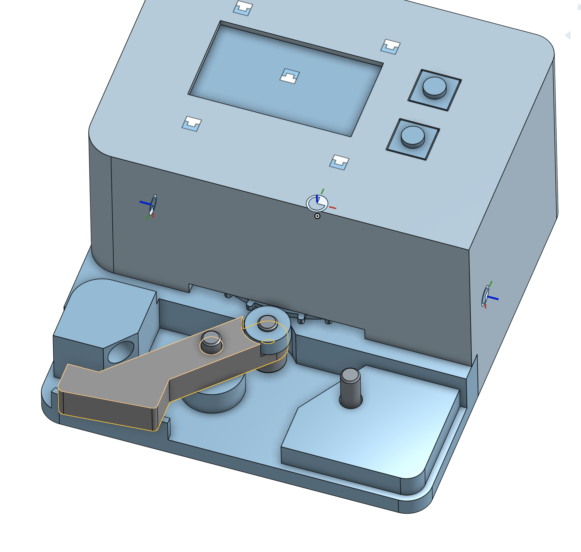
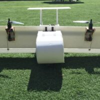
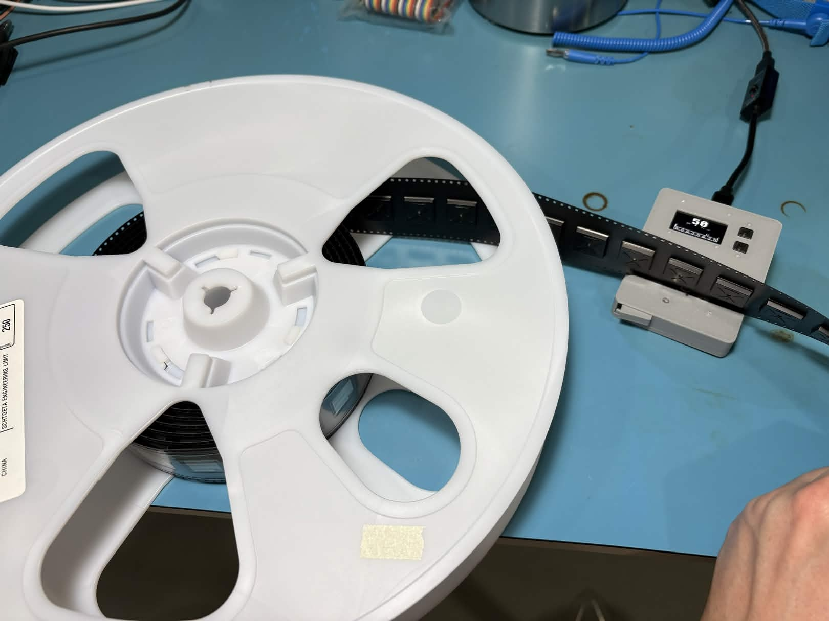
The enclosure section with the idler is designed to be intentionally low, so that componet tape with deep pockets can be counted without interfering with the enclosure of the Dotterboard. The fact that the 4mm pitch holes in the SMT tape are only engaged on one side means that the tape can effectively have unlimited width. This comes in very handy for measuring out extra wide component tapes like a partial reel of ESP32 modules.
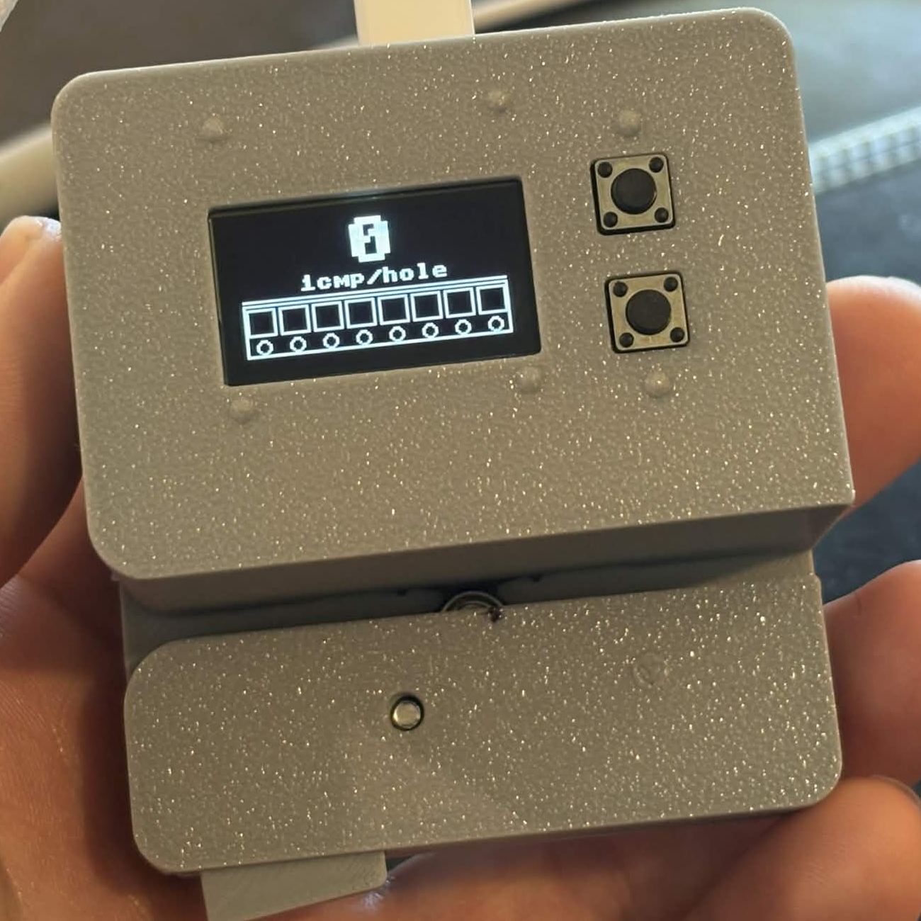
User input is provided via two buttons, and the component count as well as a graphic of the current programmed tape pitch are shown via an OLED display. I was very pleasantly surprised at how good Claude Code was at generating a simple GUI! The whole UI was generated in about 15 minutes of vibe coding, and the cute graphic that Claude generated for the SMT tape was actually quite a bit prettier and more intuitive than what I had been originally thinking of for a GUI design. The guts of the actual encoder program were another matter entirely; it took quite a long time to get a decent program for component counting that wouldn’t skip steps. My experience with AI coding seems to be that it either one-shots it on the first try, or might come up with a good fix on the second or third tries, but if it’s still broken after that, an AI agent can circle the drain for what seems like ages without coming up with anything that actually fixes the problem, while continuously adding unnecessarily complexity. After an embarassingly long time helping Claude use PIO and harrassing it about proper use of interrupts, I did manage to get the rest of the program working well, with no missed encoder counts at any tape speed (it seems like interrupts in MicroPython don’t like to interrupt I2C transactions, so the screen refreshing was causing encoder counts to be missed occasionally). While I do think that I may have had an easier time vibing this simple application in C++ (a better choice for something as real-time as a PIO + interrupt based encoder counter), the performance of the final product is still perfectly adequate when built with MicroPython.
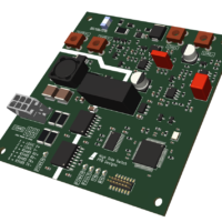
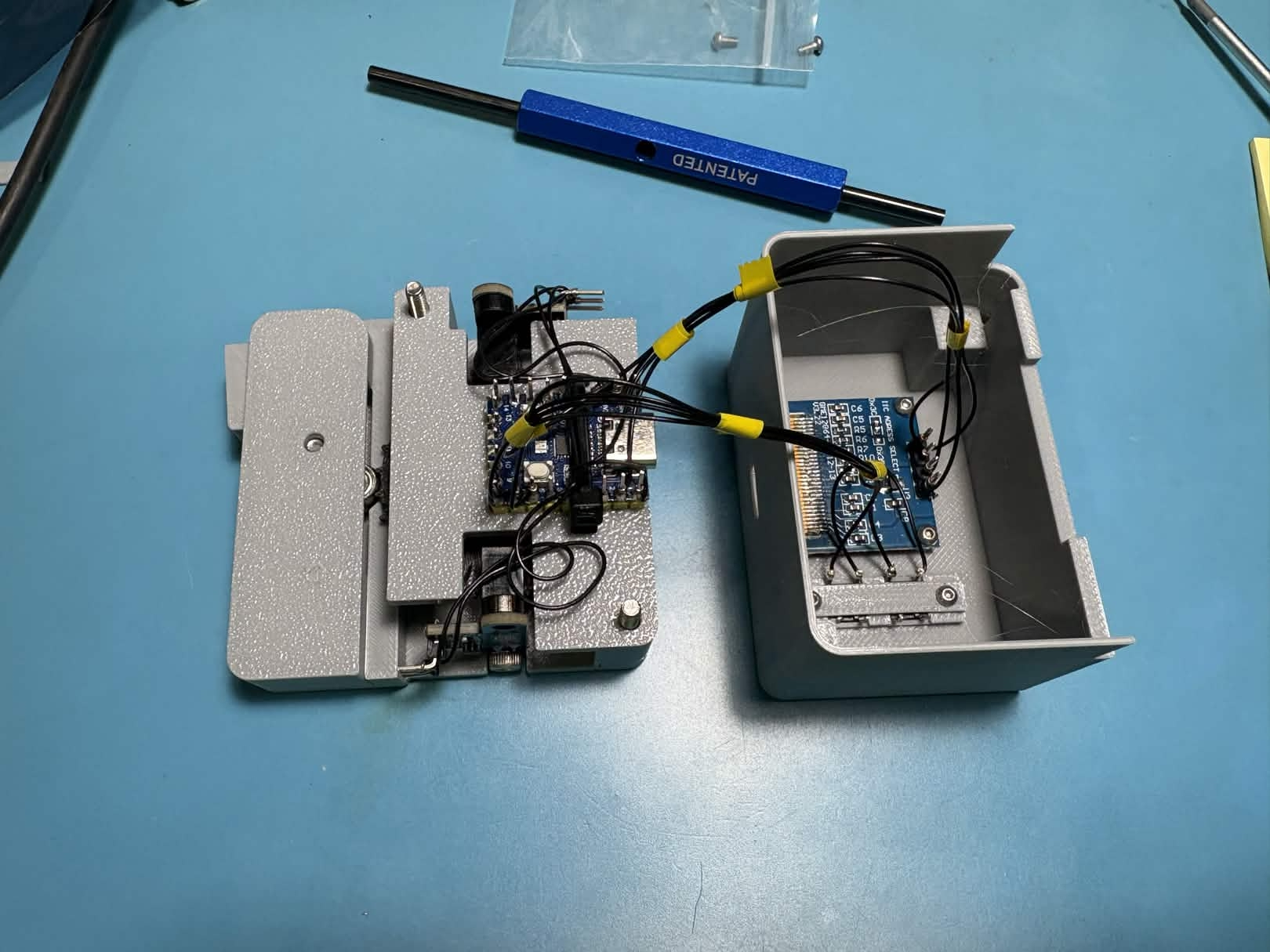
In an effort to avoid soldering a custom PCB for the Dotterboad, I decided to break out the wire wrap tools! I pushed the pin headers for an RP2040 zero module up through their plastic spacer strip until they formed decent wire wrapping posts, and proceeded to connect the two slot sensors, the OLED screen, and the two buttons with wire wrap wire. I made a fun little bench for the two through hole buttons mounted into the front of the case, and wire wrapped directly onto their legs in order to avoid building a front panel PCB.
Tada! That’s the whole thing. It plugs into USB C for power (although this could probably be extended to send data automatically to a computer if someone had an application for that). Pressing the top button increases the number of components per hole, pressing the bottom button decreases the number of component per hole, and pressing both buttons clears the part count. It’s capable of counting up and down (including negative numbers), and the little SMT tape graphic on the screen updates to reflect the number of components per hole (or the number of holes per component, for larger parts).
I’ve made the whole thing open source on GitHub in case anyone else wants to make one! It would be relatively easy to consoldiate the buttons, OLED, and RP2040 into a simple PCB, which would cut out all the cursed wire wrap hackery and also allow the case to shrink a little bit. If enough people are interested in building or buying one, I’d consider making one! Drop me a line at john[at]pantsforbirds.com if that sounds like something you might want.
If you do build one, I’d love to hear from you! This tool has already saved me quite a few hours of counting parts, so I hope that others might be able to get some use out of it as well.
Amazon Shopping List (incomplete)
- M2x3mm Screws (or mounting OLED and buttons)
- RP2040 Zero Modules
- 3x7x3mm Ball Bearings (one for idler, one for sprocket wheel)
- IR Slot Sensors (two for quadrature encoder)
- Spring Kit (I used the 0.4x4x15mm spring for the idler)
- Various M3 Socket Head Cap Screws
Mechanical Design
Join the Discussion!
Interested in building a Dotterboard or chatting with people about it? Join the Pants for Birds Discord Server and post in the #dotterboard channel!