Background
In the course of home-etching a bunch of PCBs, I’ve spent many hours hunched over my drill press squinting at tiny drill bits and trying to line them up with pads for vias and through holes. These pads can be quite small: the smallest rivets I use have a pad size / head diameter of just 0.9mm, and a drill bit size of 0.4mm. After doing this for a few years, I came to the conclusion that there must be a more ergonomic and accurate solution to this problem.
I had previously used a CNC mill to drill and route through-holes, but I wanted to avoid having to set up a computer with GCODE every time I wanted to pop a few holes in a PCB. Furthermore, the laser printer that I use to lay out traces and pads has scaling that is off by a few percent along one axis. This really isn’t an issue, as most of my PCBs are pretty small, and is only really noticeable as an extra-tight fit when I have pin headers of 20 pins or more. However, when this slight scaling error is integrated across a whole PCB or a panel, if a CNC mill doesn’t have its scaling adjusted to match, it could drill holes that are millimeters out of place compared to traces and pads. In order to avoid the effort having to calibrate multiple pieces of machinery to the same scale factor, I wanted a solution that could allow me to drill more accurate holes without the help of computer-controlled actuators.
Similar Solutions
I noticed that other homebrew PCB enthusiasts had created camera-assisted drill press designs that utilized cheap USB microscopes installed under dremel drill presses. One design even modified a drill press to drill from under the PCB in order to stop debris from falling on the camera lens! These designs seem to work great, but I had a few other design features that I wanted in my own drill press camera system.
- No external PC required (standalone microscope, ideally with its own screen).
- Removeable / no permanent modifications to my drill press (I often use it for woodworking and metalworking) in addition to PCB drilling.
- HDMI output to drive an external display for a more detailed view.
- Easily adaptable to fit multiple types of microscope cameras.
Drill Press Camera Design
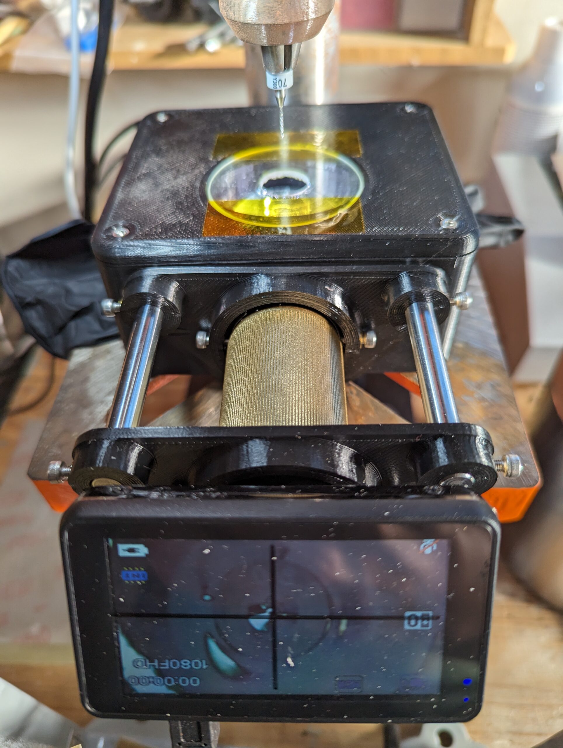
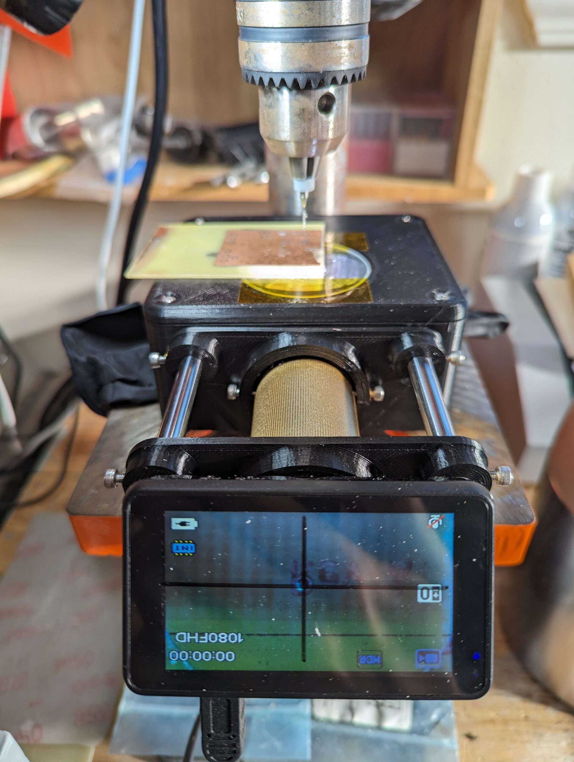
Since I wanted my design to be removeable from the drill press, I decided against the classic option of mounting the camera directly under the drill bit, as this often requires a good deal of space below the drill press table and some permanent modifications to the drill press to mount the camera solidly. Instead, I opted for a periscope design, where the microscope camera would lay horizontally on top of the drill table, and a 45 degree mirror in front of the microscope camera would provide a view of the underside of the PCB.
Even better, with this design topology, I could use my old Andonstar ADSM201 HDMI microscope camera, and the screen would rest at a convenient viewing angle for me to look at while running the press!
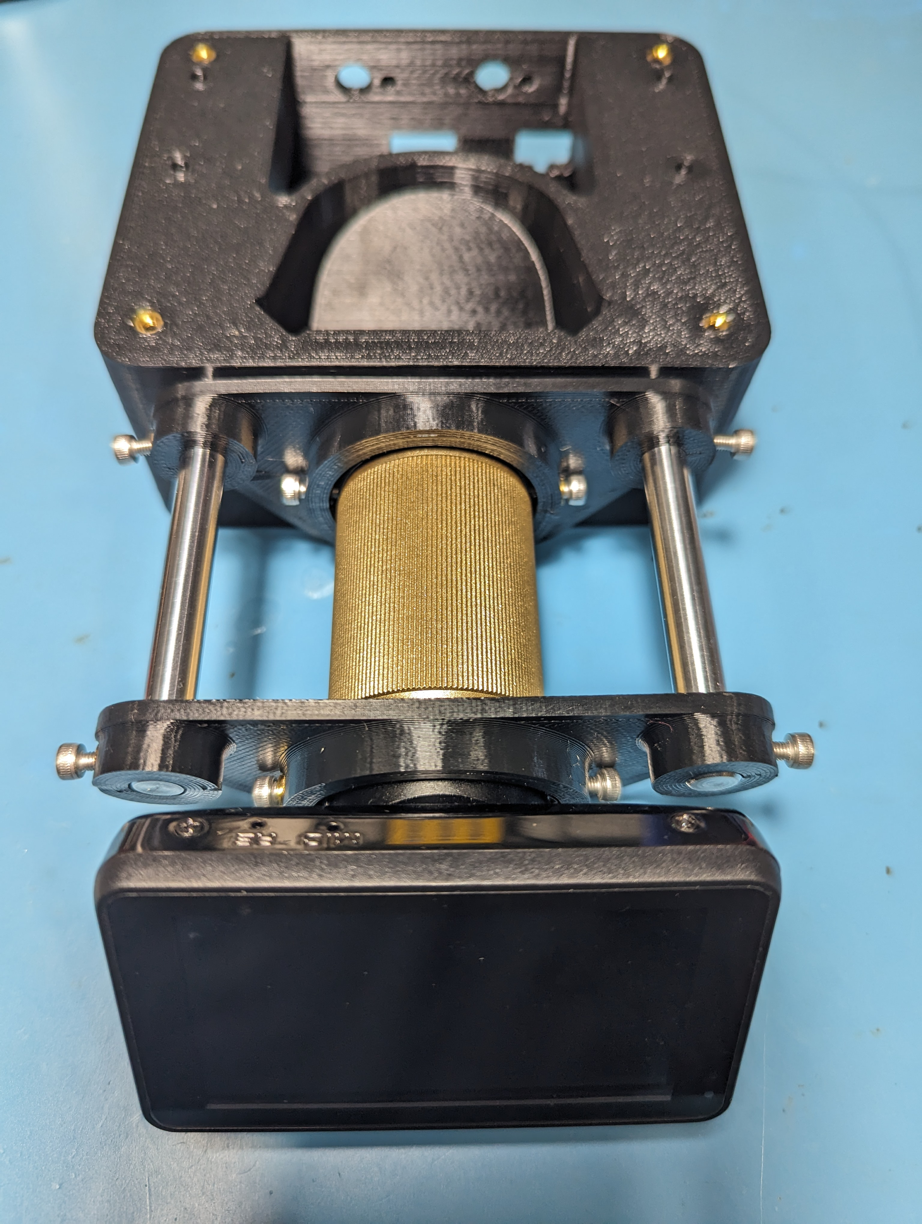
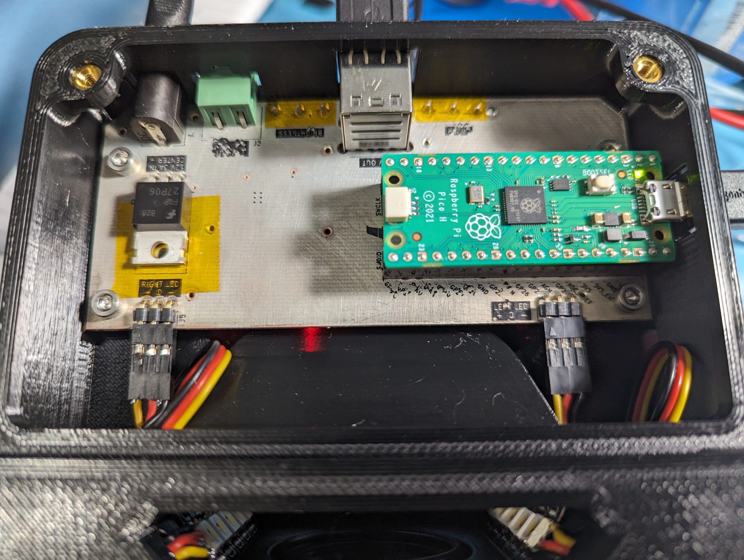
Once I settled on the periscope layout for the microscope camera, the next task was finding a way to illuminate the bottom side of the PCBs being drilled in a manner that wouldn’t introduce glare to the microscope lens. To do this, I positioned two high-density strips of RGBW LEDs on either side of the microscope lens. These LEDs are individually addressable over a one-wire interface, and have an extra dedicated white LED in addition to the usual RGB LEDs found on similar WS2812B LED modules. The extra white LED is quite bright, and very helpful when attempting to cram the maximum amount of lumens into a smallish space like I was with this project. The color and brightness of the LEDs is controlled by a Pi Pico that reads two potentiometers positioned at the back of the mirror enclosure. White light is ideal for maximum brightness, and provides good illumination for most PCB drilling applications. Other colors of light can be helpful for providing increased contrast when drilling colored substrates or looking for particular colors of fiducials.
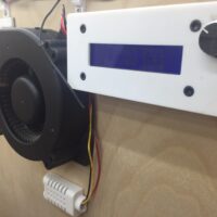
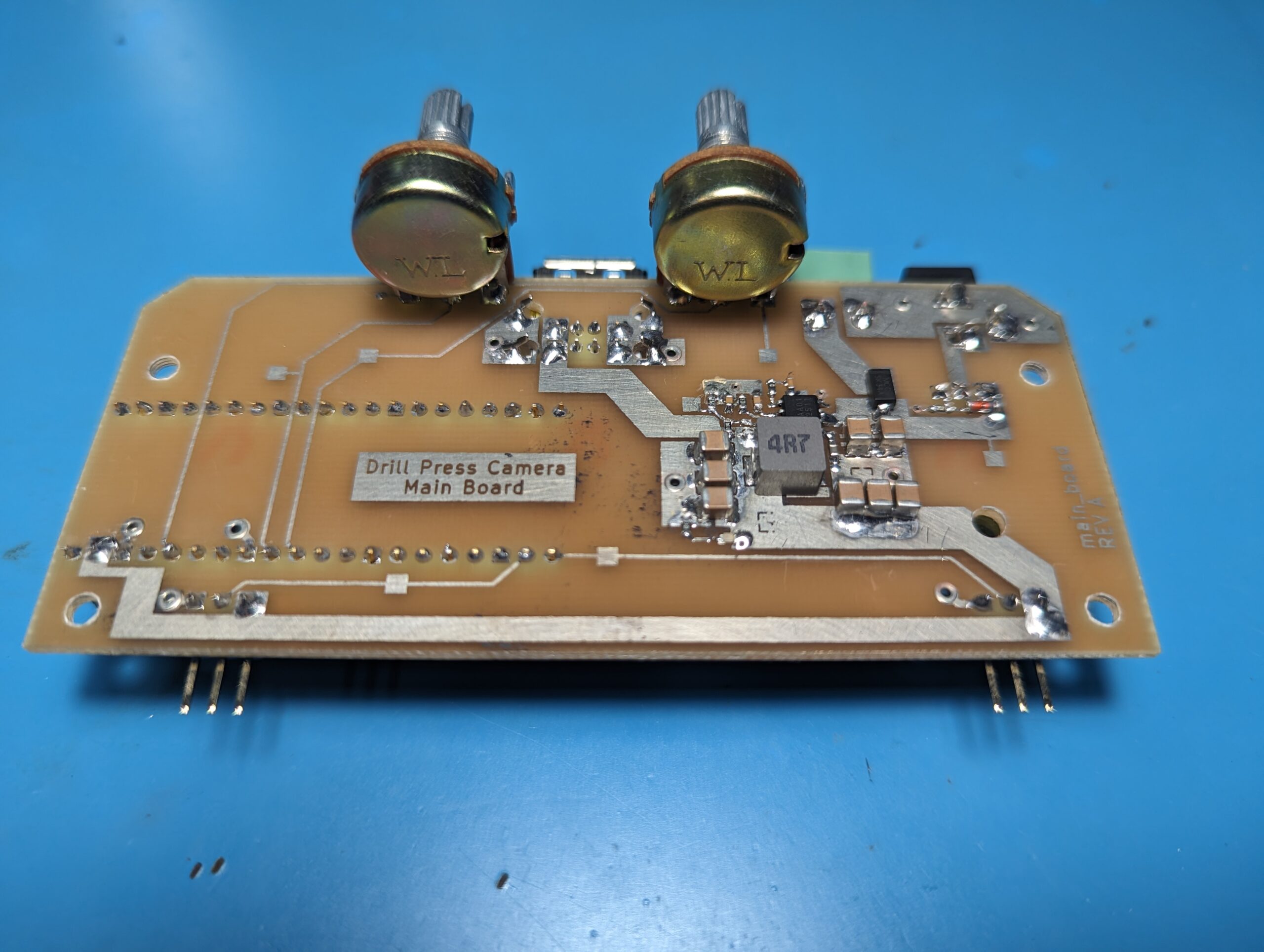
The electronics of the microscope camera are powered by a PCB housed in the back of the mirror box, creatively named the “main board”. The main board includes a 5V 4.5A buck converter capable of powering the onboard LEDs, 2x USB devices (intended for the microscope camera an a small external display), as well as the onboard Pi Pico microcontroller. In addition, the main board also provides an extra +12V output in case a microscope camera with a 12V power input is used. Color and brightness control potentiometers are installed directly onto the main board, and can be accessed from the rear of the mirror box enclosure. The whole shebang (main board, microscope camera, external display) can be powered by a single 12V 3A power adapter that plugs into the back of the main board via a 5.5mm barrel jack.
The camera assembly is fastened to the drill press with some strong magnets. I’ve found that when running at high RPMs, vibrations can cause the assembly to shift slightly, but the addition of a high-friction layer between the magnets and the drill press table (in the form of something as simple as a latex glove) seems to be enough to stop the assembly from moving. I’m planning to modify the bottom cover of the camera assembly to add some M5 thumb screws to properly clamp it through the bottom of the drill table.
The bottom of the PCB being drilled is supported on a circular piece of glass with a 16mm hole drilled through the center. This transparent glass piece allows the underside of the PCB to be illuminated and viewed by the microscope, and the hole at its center ensures that it won’t interfere with a drill bit passing through the PCB, as long as the mirror box is properly aligned with the drill bit. There is an opening in the bottom of the mirror box enclosure just below the angled mirror in front of the microscope lens. Any fiberglass or copper shavings that drop through the hole in the glass circle can be blown out the bottom of the mirror box with a quick puff of air applied in the direction of the hole. Most shavings that land on the periscope mirror are out of the focal plane of the microscope camera, so they generally just show up as a slight blur. As such, frequent cleaning isn’t strictly necessary, but does help improve image quality. More extensive cleaning of the periscope mirror can be completed by removing the circular glass pane, or by unscrewing the top of the mirror box enclosure.
Initial tests of the drill press camera showed the field of view of the microscope to be a circle with an approximate diameter of 16mm at the bottom plane of the PCB. This means that the hole drilled in the center of the glass circle is about enough to cover the full field of view of the microscope, so the transparent glass circle isn’t entirely necessary. The glass circle could quite easily be replaced with a 3D-printed plastic circle with a 16mm hole in the middle, with no real impact to the microscope’s field of view.
Usage Instructions
Using the drill press camera is quite simple! My general worflow goes something like this:
- Install mirror box assembly onto drill table with magnets. Throw a latex glove under the magnets for good luck (and better resistance to movement while the drill press is vibrating).
- Plug in the mirror box main board to power, and connect the microscope camera and optional external screen to the main board via USB.
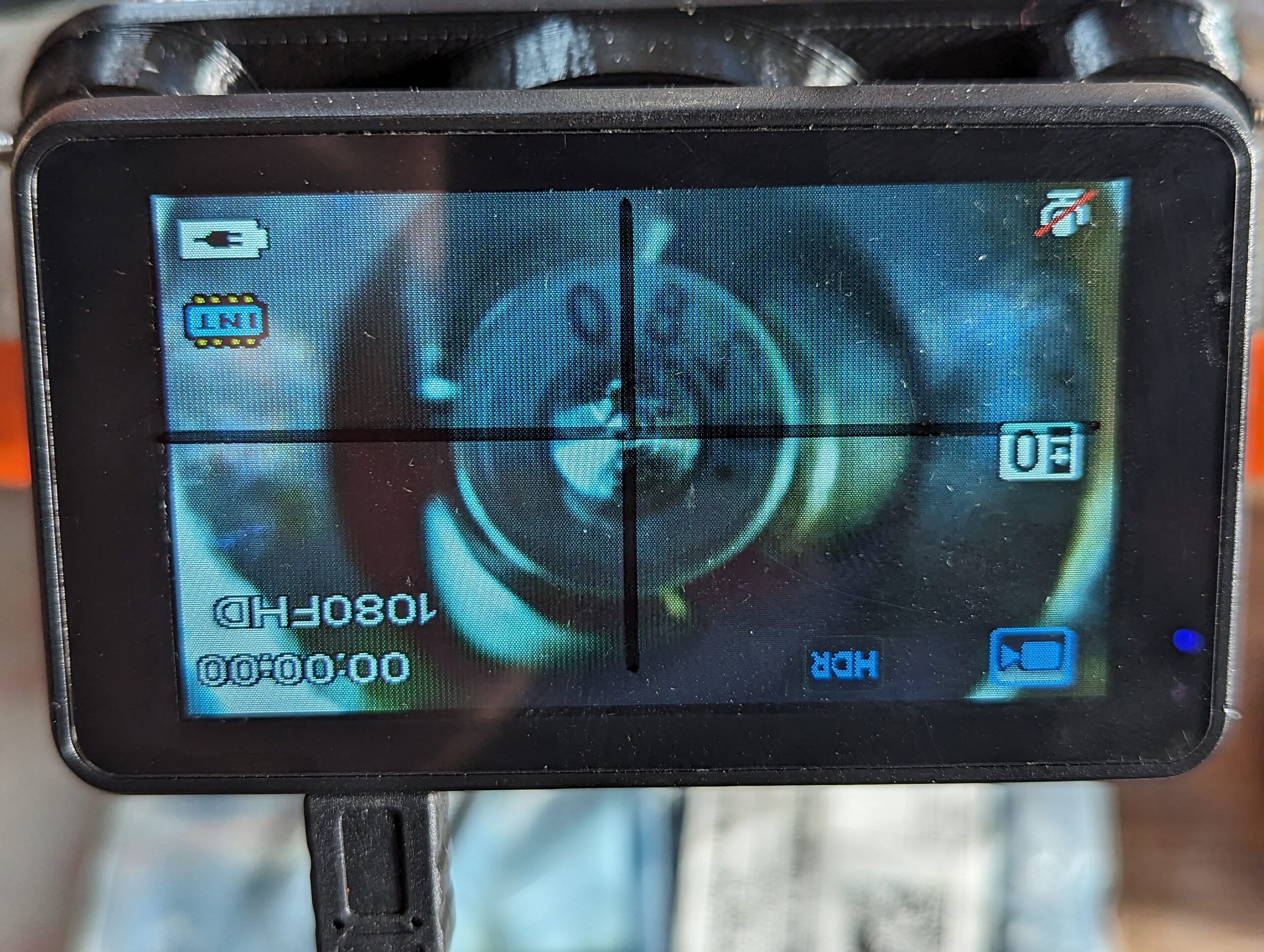
- Bring the drill bit down to the focal plane of the microscope camera. Mark the position of the center of the drill bit on the screen, either using an electronic crosshair setting (available on some microscope cameras) or a washable fine-tipped marker (I use a vis-a-vis marker on the plastic cover of my microscope camera’s screen). If your screen doesn’t have a plastic cover, I recommend using a projector transparency to mark the crosshairs onto instead of drawing directly on the the surface of the screen.
- Set the LED brightness and color as desired for best visibility of your PCB and its drill features.
- Place the PCB to be drilled on top of the mirror box’s glass circle, with drill marks on the bottom side.
- Use the crosshairs on the screen to line up your drill bit with the points you want to drill.
- Happy drilling!
Project Files
CAD models, MicroPython code (for the Pi Pico), and gerber files (for the PCB) are available on this project’s github repo.
Parts List
- SK6812 High Density RGBW LED Strip
- 8mmx150mm Hardened Steel Rods
- 2in Circular Mirror
- 2inx3mm Glass Disc
- 12V 3A Power Supply
- PCB and components (see BOM, or email me if you’d like to order one)!
- M3 Heat-Set Inserts
- M3x6mm SHCS
- M3x10mm SHCS
- Andonstar ADSM201 USB Microscope
- ALTERNATIVE PART if you have an external display and want higher resolution and crosshair functionality. You will need to make some new camera mounting brackets with a slightly larger diameter, but everything else should work fine.