Electronics Kit Now Available!
Update 2023-09-05: I finally got around to redesigning the electronics for this kit, and got some PCBs made for an improved 7-segment display as well as a new control board based on a Pi Pico! I also rewrote the firmware in MicroPython to make it easier to play around with. The full kit is available at my webstore, pantsforbirds.com, but of course the updated design and code files are still open source and available on the github repository.
Use coupon code SPEEDSIGN50 for $50 off kits in the first batch! This is mostly an incentive for dealing with any hiccups we’ll encounter while ironing out the order process, and will be removed when the first batch is sold out.
Project Writeup
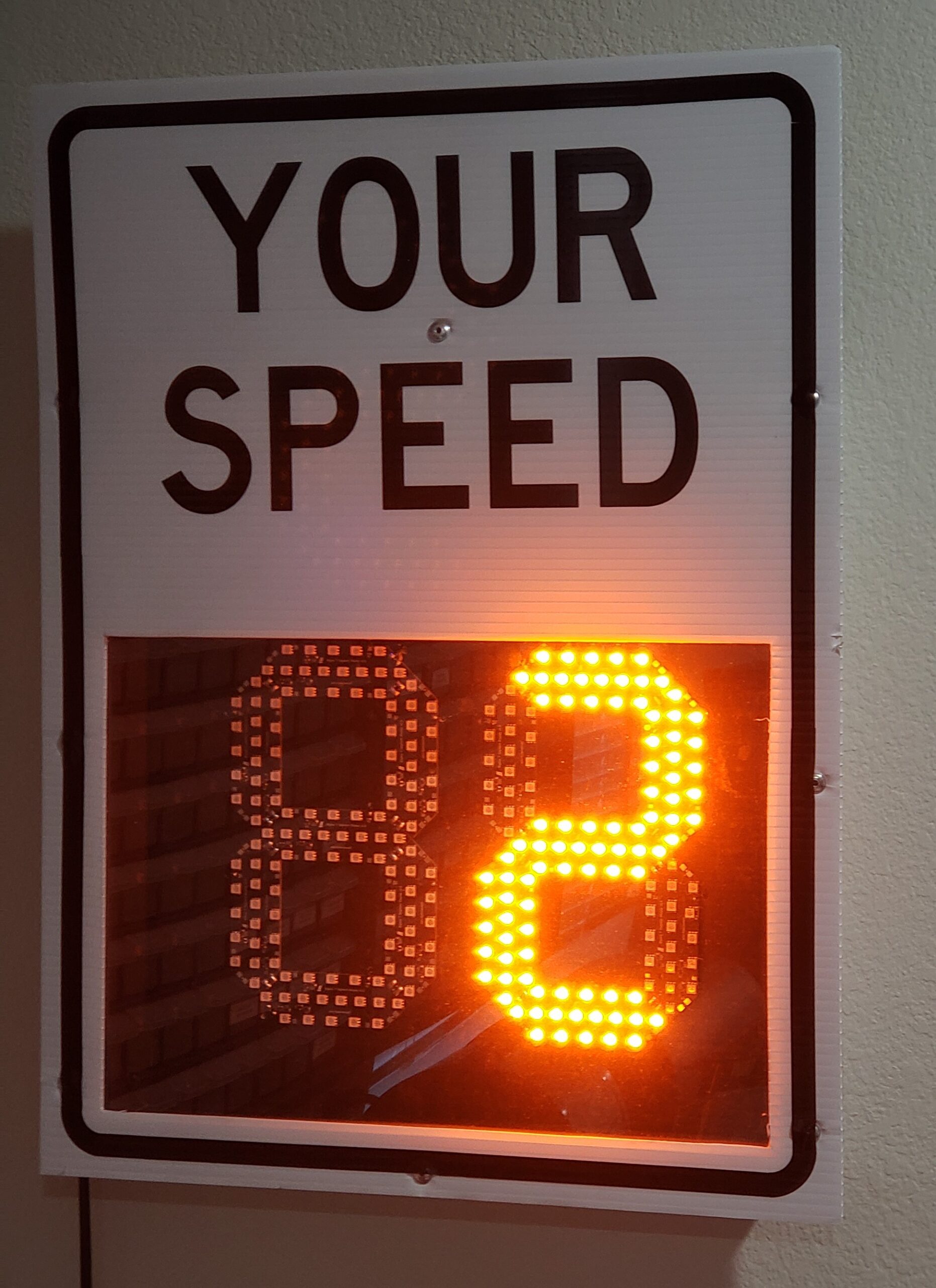
For Halloween 2020, I decided to build a replica of a radar speed sign using an Arduino and an HB100 doppler radar module. This writeup is gonna be a bit fuzzy, since as usual, I decided to document the project a tasteful 8+ months after it was complete. Have fun reading my semi-coherent image and schematic dump!
How the Radar Do
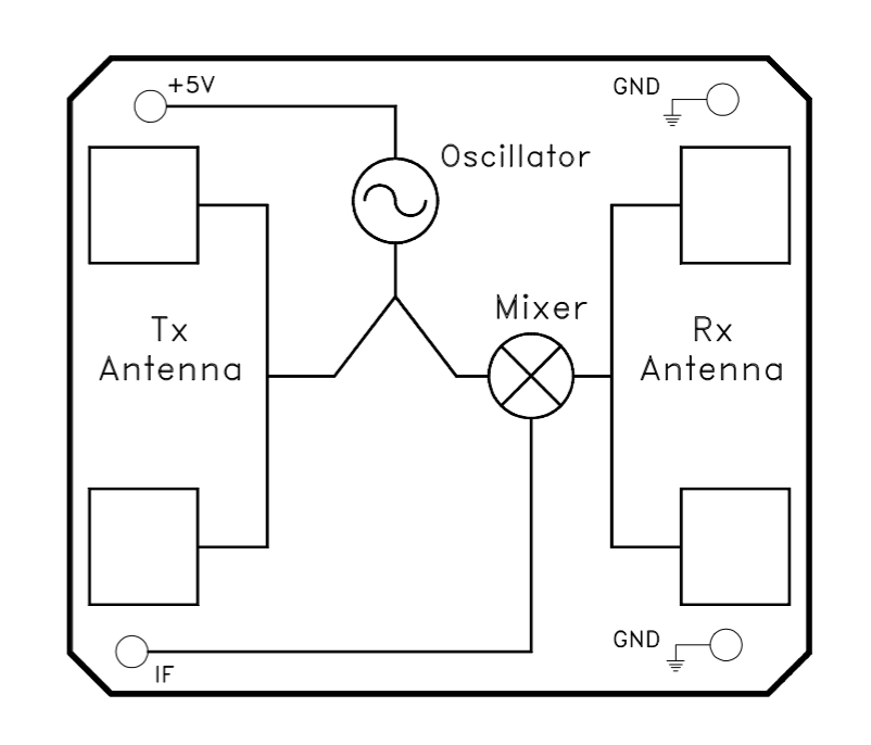
The project uses an HB100 doppler radar module and a pre-amplifier circuit in order to convert movement of objects in the HB100’s field of view into a square wave that gets fed into the Arduino Nano. Radar makes everything sound fancy, but in this case it’s no more complicated than what you would find in one of those supermarket automatic doors that triggers when some leaves blow by. The HB100 transmits a 10.525GHz carrier signal, which is reflected off of a moving target (in the case of this project, a person walking across a room at close range). The return signal from the moving target is doppler-shifted, and is thus a higher (or lower) frequency than the carrier, depending on whether the target is moving towards or away from the transmitter. By mixing the transmitted 10.525GHz signal with the reflected signal, the HB100 produces a signal that is the difference of the two frequencies. Fortunately, for objects moving at non-relativistic speeds, this difference frequency is usually very chewable for even the dumbest of microcontrollers, as it’s usually in the range of a few Hertz.
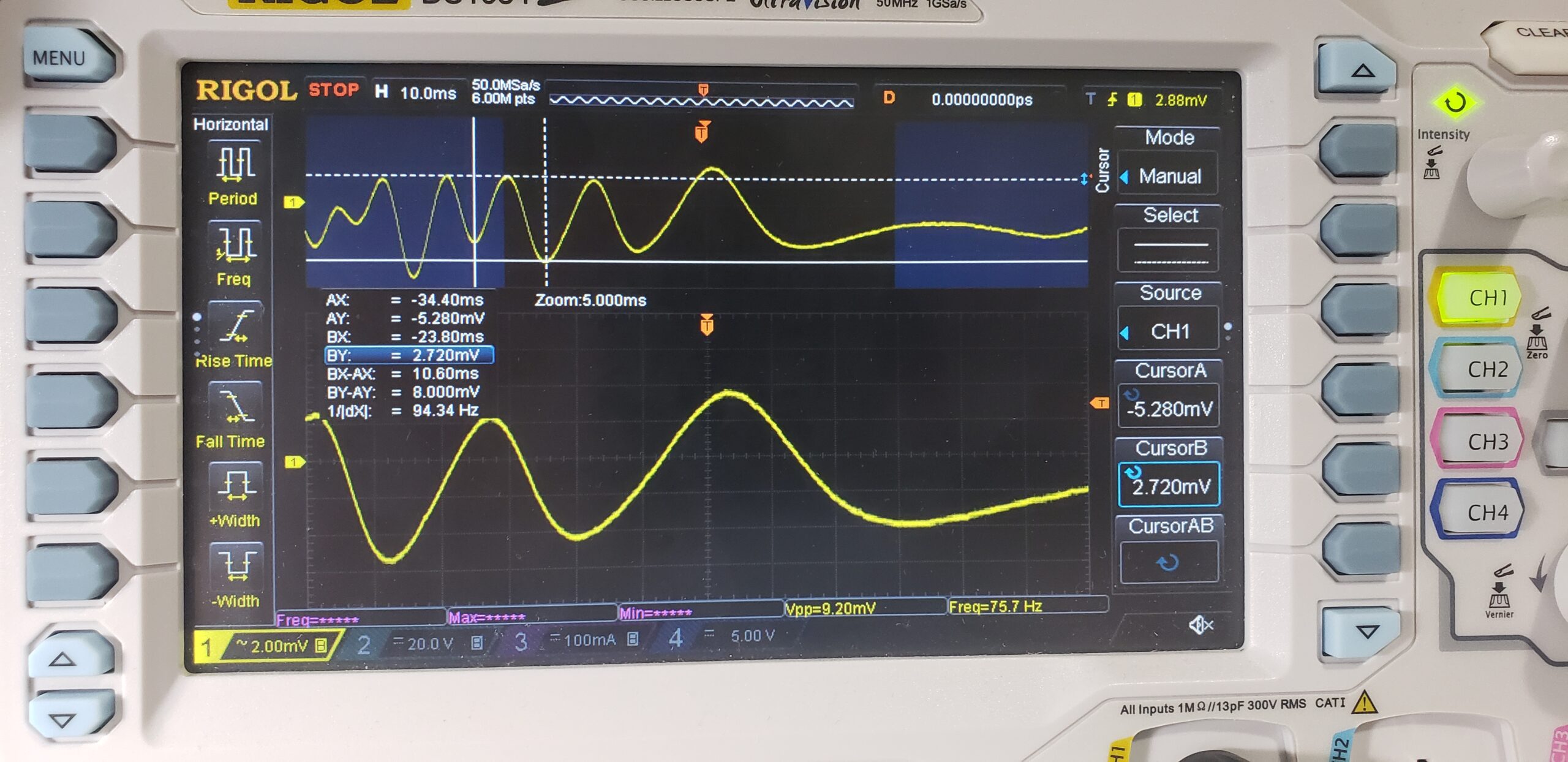
In order to get the difference frequency into a format that can be processed by a microcontroller, the signal passes through a two-stage preamp circuit which amplifies it from a lil squiggle into a rail-to-rail square wave. The pre-amp circuit isn’t that interesting, and is ripped straight from the datasheet. There are some capacitors in parallel with the feedback path in order to generate some poles that roll off the frequency response around 72Hz, stopping the pre-amp circuit from amplifying high-frequency noise that is beyond the range of interest. Also note the chunky (4.7uF) AC coupling caps between stages. These coupling caps are yuge because they need to have a low impedance at the frequencies of interest (<100Hz). If we look at the 12k resistor used for the IF load, and assume that the HB100 IF circuit has a characteristic impedance in the range of 12kOhms, we can see that a 4.7uF capacitor provides an impedance lower than the characteristic impedance all the way down to around 2.8Hz. Neat!
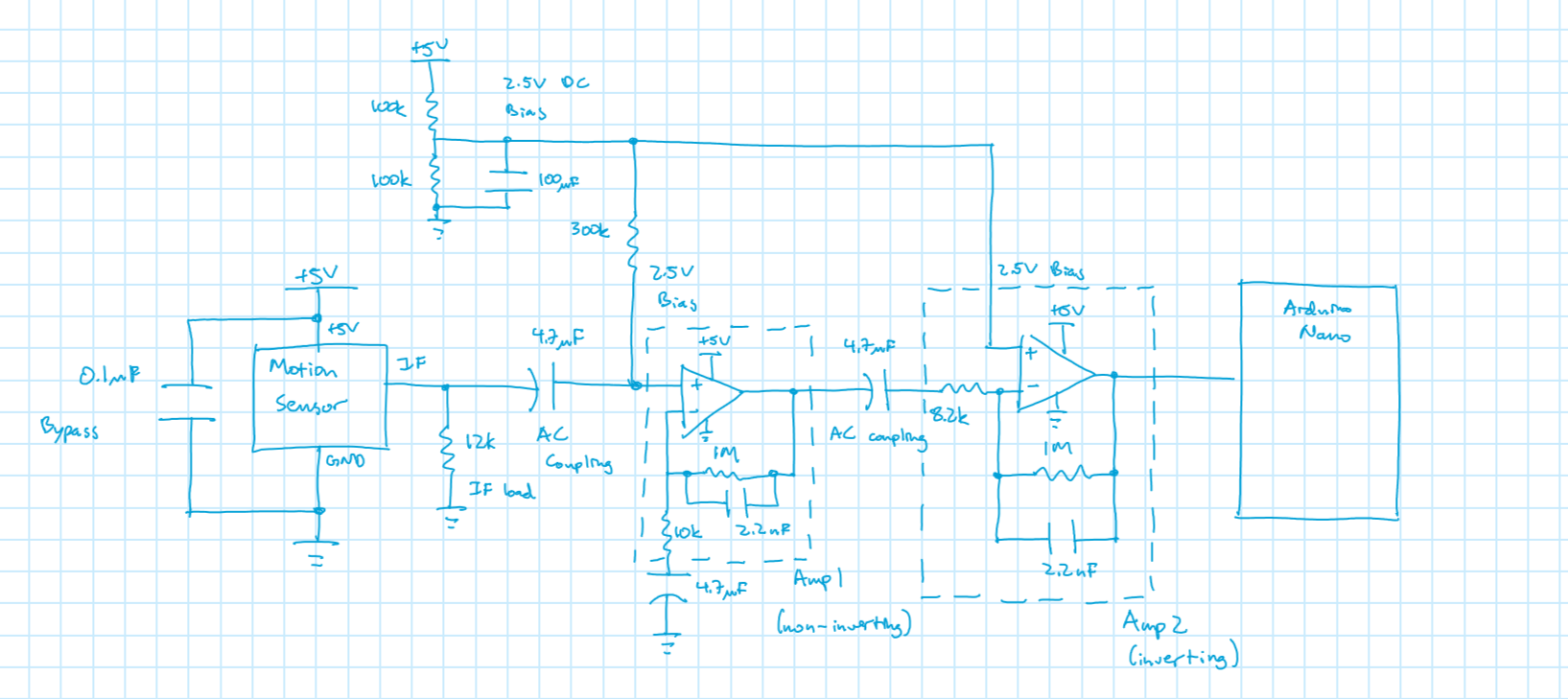
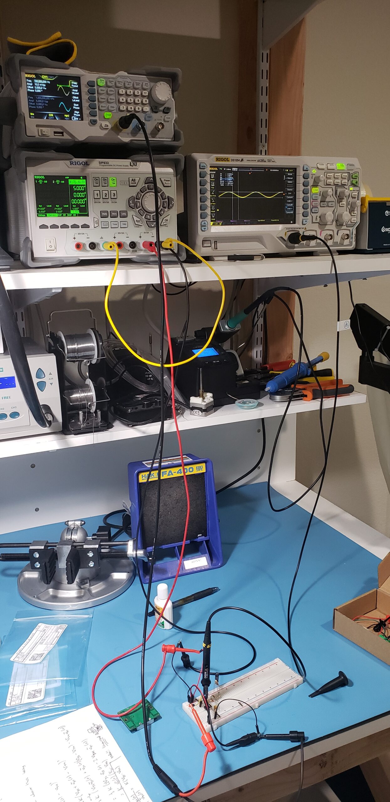
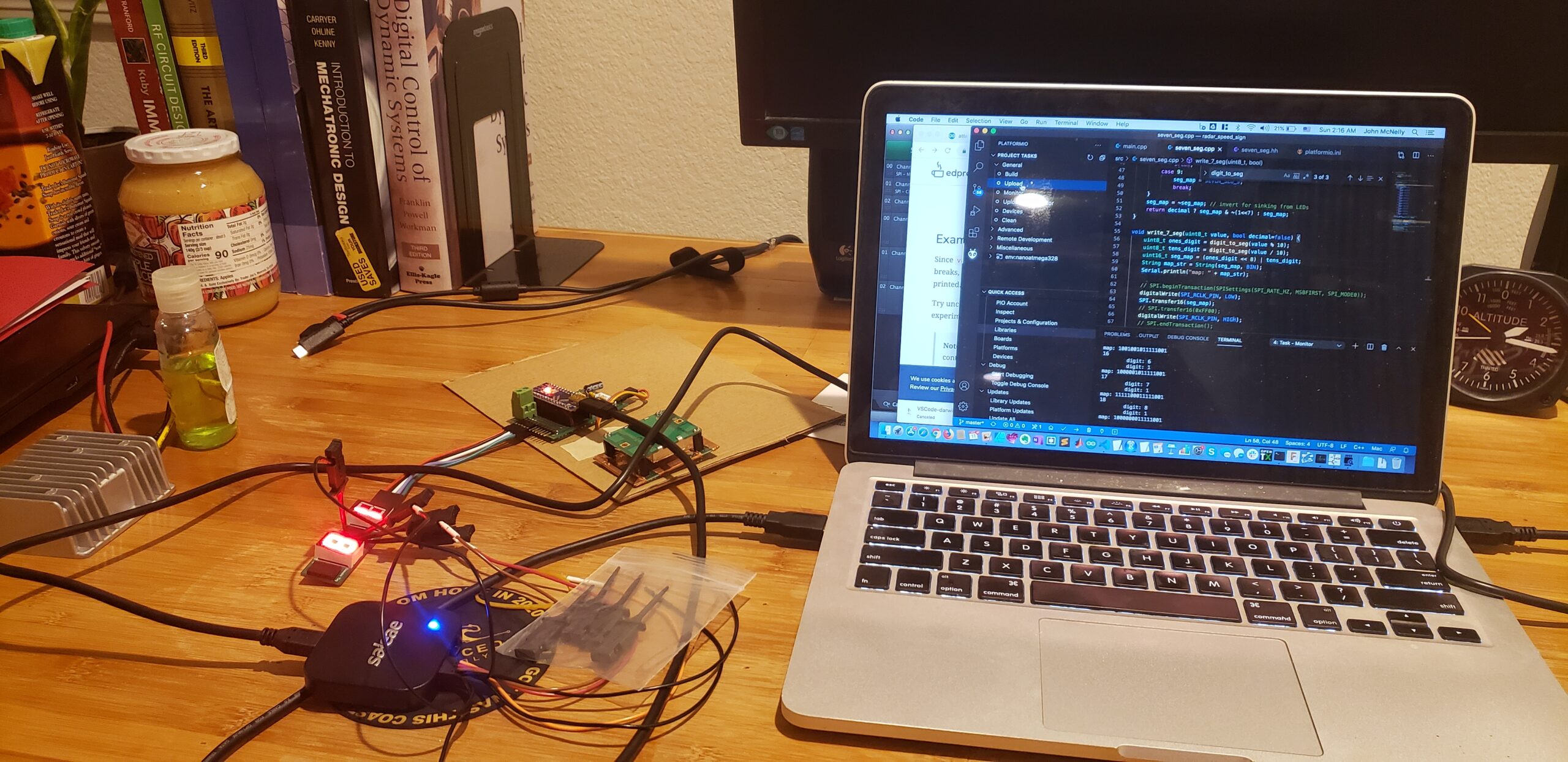
Once the preamp circuit was working, it was pretty simple to stick the output straight onto one of the Arduino Nano’s digital inputs. Input interrupts were used to time the pulses and estimate the frequency of the signal, which can be converted into velocity using the doppler radar equation.
Bigass 7 Segment Display
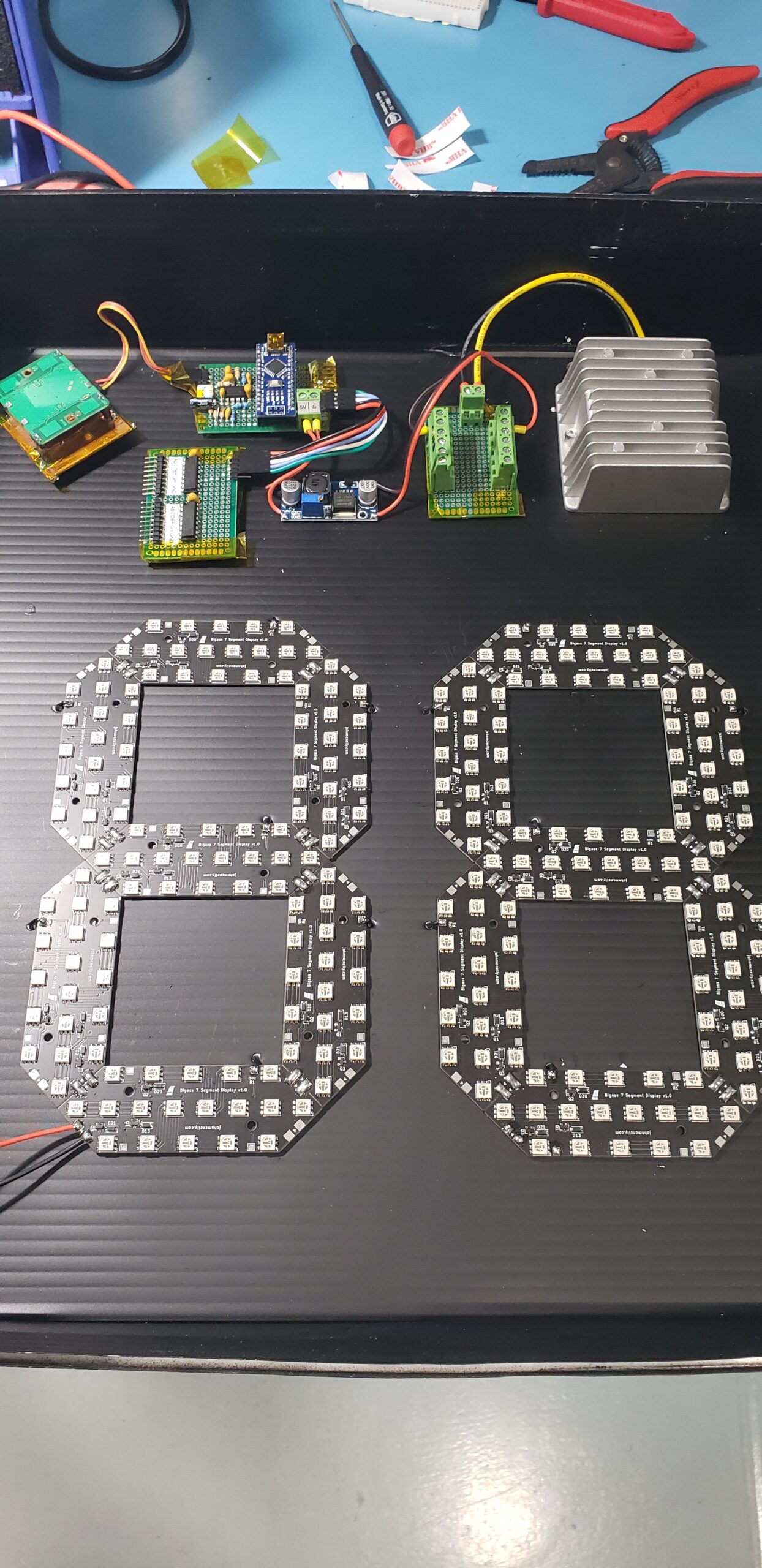
From the beginning, the real pizazz for this costume was always going to be the giant LED 7-segment display. I’d been wanting to make one for a long time, for no particular reason other than whee LEDs shiny, and more LEDs = more shiny. There have been plenty of 7-segment display implementations with all kinds of hardware, from the WS2812B chips controlling segments with individual addressing to cool multiplexing schemes. However, my favorite approach has always been the tried and true SPI shift register configuration. Using two SPI shift registers (the good ol’ 74HC595), each digit is controlled by a single shift register, with a single segment responding to a single bit output from each shift register. In the past, I’ve used the 8th bit output to control a decimal point, but that wasn’t necessary for this particular project.
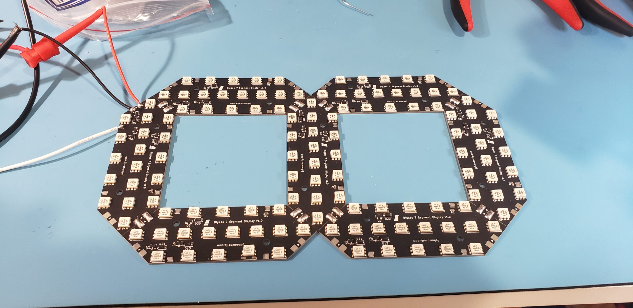
In order to make things easy and reasonably professional-looking, I designed a custom modular PCB containing 8 high-power amber LEDs. These hexagonal PCBs could interlock to form a 7-segment display digit, and contained the necessary current-limiting resistors, and switching transistors for turning the digit on and off. Solder pads at the interlocking edges of each PCB were used to share +12V and GND to the entire digit from any single powered segment. Additional solder pads on the edge of each segment connect to the gate of the switching MOSFETs, allowing a low-current enable signal from the shift register to control the segment of high-power LEDs. I should have added a series resistor to this gate network to protect the MOSFETs from ESD…in my late-night haste to assemble the costume, I managed to zap through the oxide layer on several MOSFETs with ESD, killing them. That caused a good amount of debugging headache! If I were to sell these segments or something, I would probably change the drive MOSFET to an NPN BJT with a base resistor for added robustness.
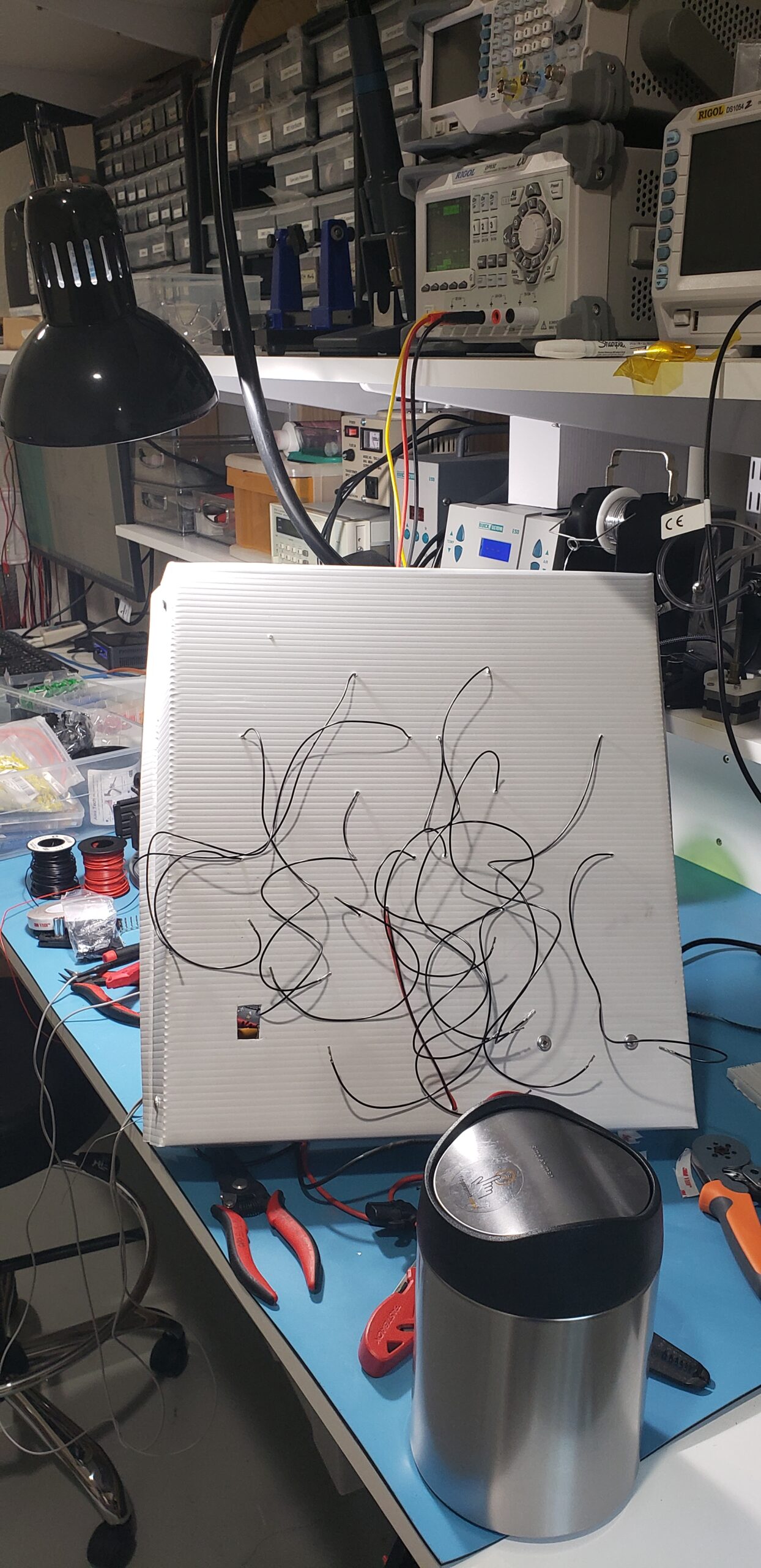
Putting Things Together!
Links
Here’s a list of some of the parts that I used, in case people are looking! These are Amazon affiliate links (gotta make some of them Bezos Bucks).


[…] technology that powers them is quite cool, which is why John McNelly wanted to construct his own DIY version that closely reflects the actual […]
Wow amazing! Bravo!
I want one, how much please!
Regards
Ha, thank you! I’m glad you liked the build. All up I think it cost me under $200 including the PCBs and parts. It was a very fun project!
[…] that powers them is quite cool, which is why John McNelly wanted to construct his own DIY version that closely reflects the actual […]
this is not my area, but I really want to be able to make one of these. could you do a parts breakdown so that I could order them off amazon, for example? I know my dad can look at the schematic and he has an oscilloscope, but I would like this first one to be as easy and as cheap as possible once we get started. Thank you for any and all insights!
Hi! I’ve added a list of parts with the Amazon links that I used at the end of the article. That list should cover most of the electronic components you see in the photos, minus some basic things like through hole resistors (I used regular 1/4 watt resistors). Mechanical parts were all sourced from Home Depot, with the exception of some pop rivets that I think I got from Amazon (I can dig up that link too if you need it). Feel free to reach out to me through the contact form or post a comment here if you have additional questions! I’d love to see how things turn out if you give the build a shot.
Very Nice.
Curious: I looked at the circuit for the LEDs in your segments, you have three banks with all colours linked together in each bank.
Why not have the three colours in individual banks?
Use three PWM pins on the Arduino to light them, then you have 256x256x256 colours to chose from.
Hi Palingenesis!
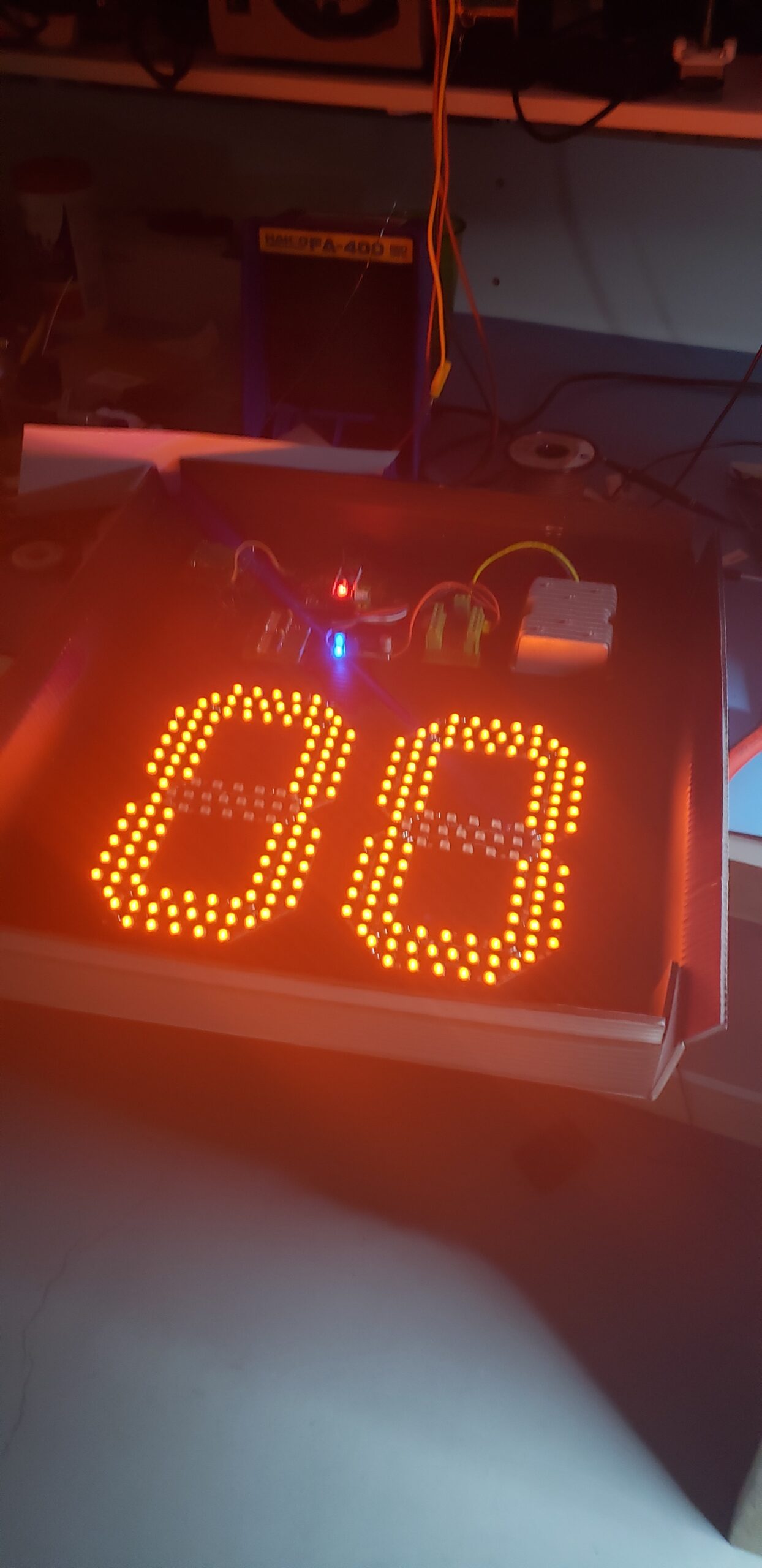
The LEDs that I used are high power amber LEDs. The way they get their extra brightness is by putting three parallel amber LEDs in each package, effectively replacing the red, green, and blue LEDs commonly seen in the RGB leds of a similar profile with a single set of three amber LEDs. Since all the LEDs are the same color, only one driver circuit per segment is required.
Ah, it all makes sense now 🙂
Nice project, and good job, I wondering if this can detect a vehicle speed, where I live there is some idiots that speed in the playground zone and will be nice to have one of this.
Sorry for my english…
Hi David,
This sign could detect a vehicle’s speed, if you are able to sufficiently extend the range of the HB100 doppler radar unit. Since the unit is meant for detecting pedestrians in automatic door applications and the like, its antenna has very low directional gain. I’ve read in some places about people getting better range with jury-rigged horn antennas made from copper foil tape and cardboard, but it may be easiest to get a longer-range radar module off the shelf for that purpose.
Your english is great, no worries at all! I could understand your comment well enough.
We have been working on the preamplifier circuit for a while. It’s pretty noisy and we aren’t able to get this circuit working with arduino. We even used a comparator and increased the gains of first two stages but no output. Any suggestions?
Hi Pavan,
What op-amps are you using? Have you tried testing your pre-amp circuit with a function generator?
One thing to check is that your DC biasing for the op-amp inputs is correct. If you don’t provide a DC path for each op-amp input (inverting and non-inverting), the input bias current of the op-amp will charge up whatever AC coupling capacitor you are using and cause the output of the op-amp to rail.
I’ll send you an email in case you want to share a circuit schematic. Best of luck with the project!
Hi, have you try the HB100x? My undestanding is that the “x” (has a circular shape) has an output signal up to 5v and could go strait to the arduino but not really sure.
I haven’t had a chance to try the HB100X–looks like they just added the pre-filter circuit to an existing HB100 module. That could certainly be a nice option for simplifying the build!
Hi is there any possible way we could get a complete full list of every part that you use please?