For Halloween of 2024, we decided to tackle a logistically complicated costume idea that had been on our minds for a while: airline travel! Our previous Treat Security Administration costume had demonstrated that kiddos in our area are quite familiar with the routines of travelling through an airport, and that standard airport interactions in the context of the security screening area could be turned into a fun experience for trick-or-treaters. This year, we wanted to go all in and recreate the full airport experience, from booking a ticket to in-flight snacks and entertainment.
Trick-or-treating always involves some element of anarchy, so we wanted the experience to be flexible enough to accommodate the inevitably unpredictable behavior of children on a quest for sugar, while still providing enough structure to be strongly suggestive of a real airport experience. To that end, we decided that theming the event after an airline with an open boarding experience would be advantageous, as it would remove the logistical burden of assigning seats, and would provide increased flexibility for adding or removing passengers from flights at the last minute. Thus, Sweetwest Airlines was born.
The general concept of the Sweetwest Airlines trick-or-treating experience was to have regularly scheduled “flights” to candy-themed destinations in a simulated aircraft. Full-sized candy bars matching the destination candy would be handed out during each flight; for instance, flights to KitKatMandu would hand out full-size KitKat bars, and flights to Twixeltown would hand out full-size Twix bars.
| Destination Name | Destination Airport |
| Snickersville | SNK |
| Sour Punch Valley | SRP |
| Twixeltown | TWX |
| Skittleton | SKT |
| Kit Katmandu | KKT |
| Reeses Ridge | RSS |
| Switzerland | ZRH |
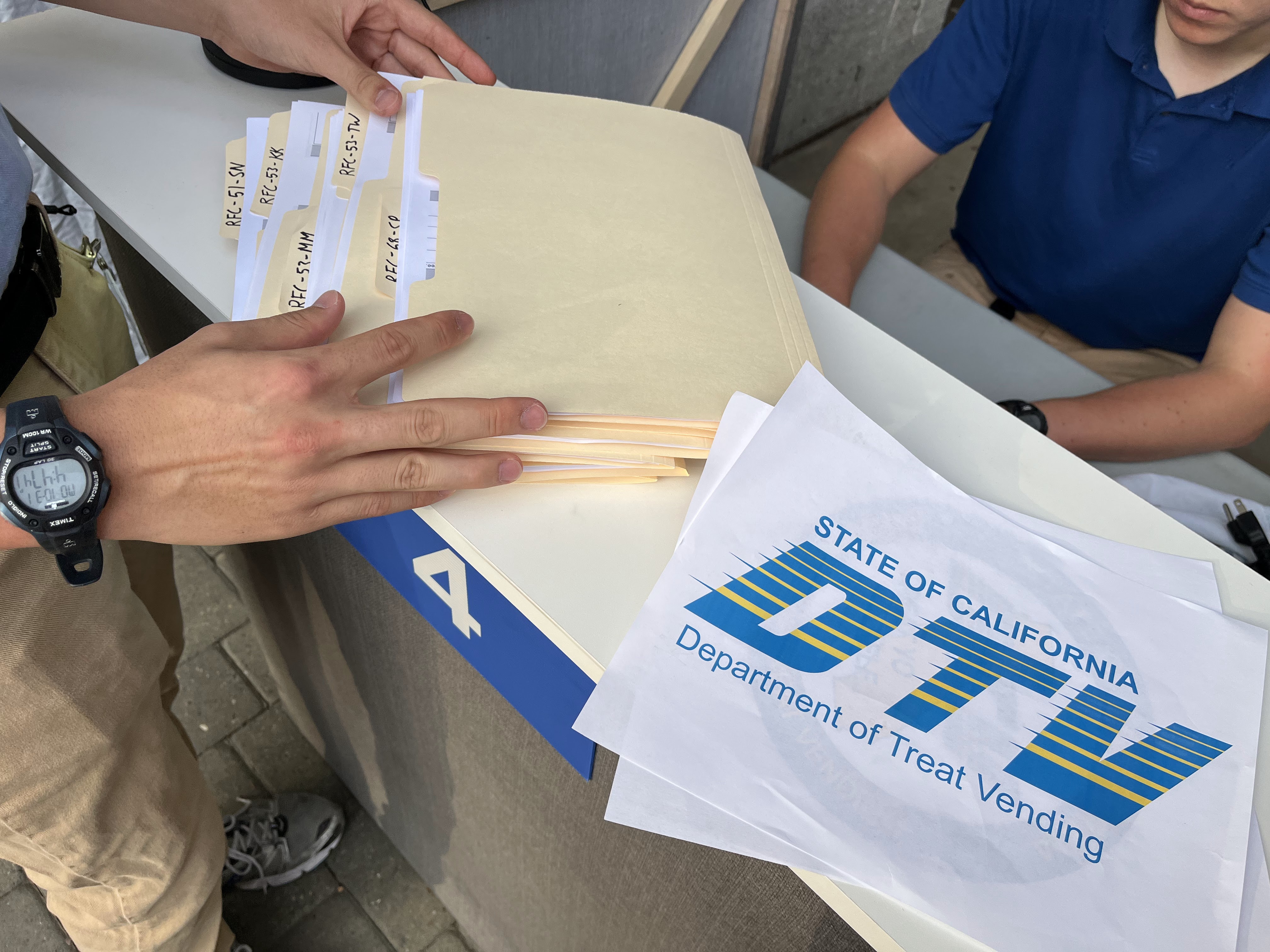
In order to board one of these flights, passengers would need to first acquire a ticket at the ticketing desk (tickets were free, but the line could be quite long). Flights were pre-scheduled with a fixed capacity, so depending on demand at the time, tickets available at the counter might be for a flight leaving in just a few minutes, or up to 90 (maybe more) minutes away. Once a passenger secured a ticket for a given flight, they could opt to wait in the terminal area, or resume trick-or-treating and return to the terminal closer to their given flight time. About seven minutes before a flight’s departure time, a boarding announcement would be made over the airport PA system, asking passengers to line up for boarding. Once the previous flight had de-planed, passengers would have their boarding passes scanned as they boarded the aircraft to enjoy the in-flight experience.
Set Design
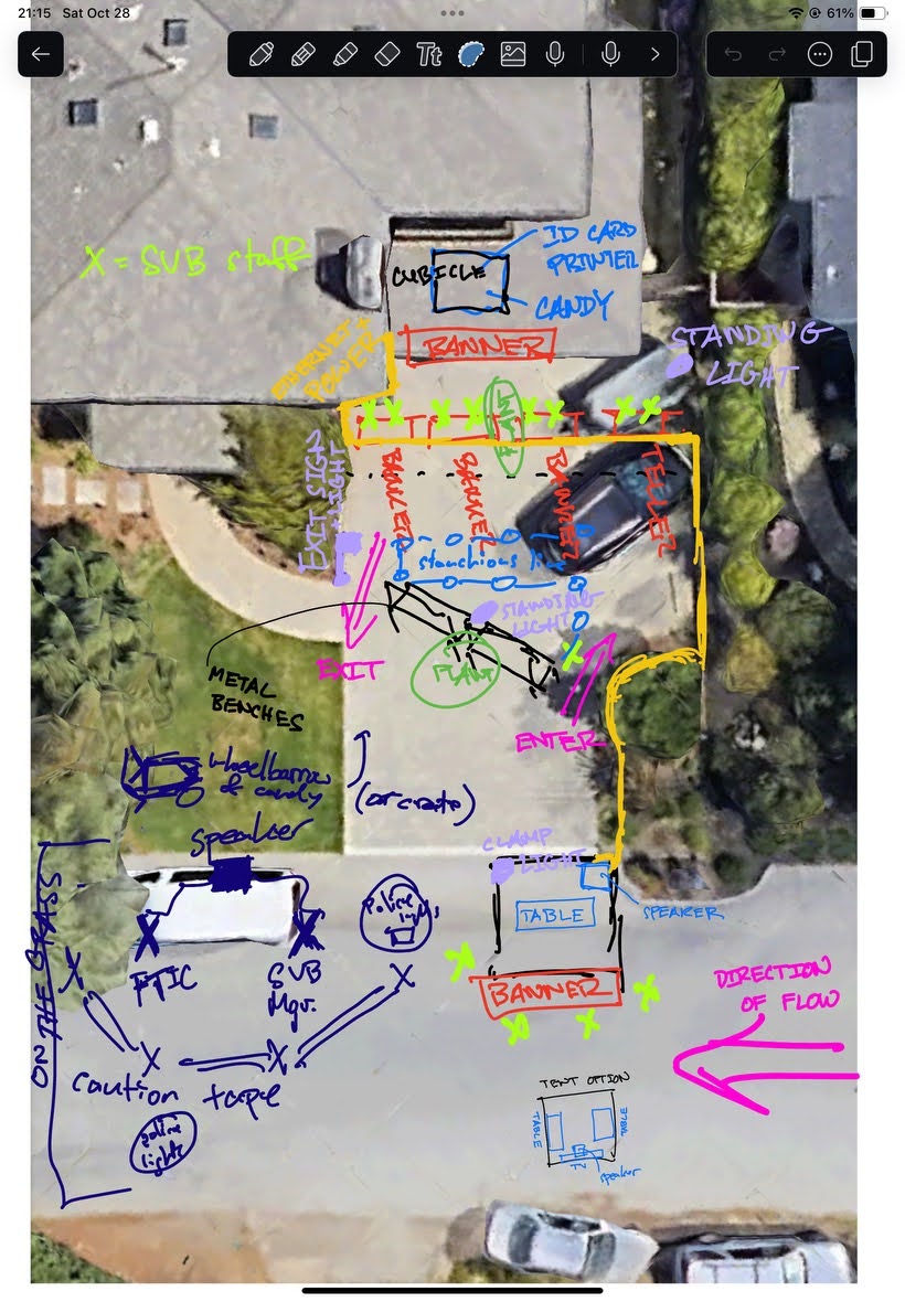
Convincing a trick-or-treater that they’ve set foot into an environment that reminds them of an airport is a surprisingly difficult endeavor. Airports are generally very expensive pieces of infrastructure, and transforming a residential driveway into something approximating a billion dollar aircraft terminal would take an ungodly amount of paper mache. Fortunately for us, enough of the airport experience could be recalled through the use of smaller props and employee interactions that five-story-high picture windows and jetways proved to be unnecessary for capturing the essence of the air travel experience.
For our airport set, we had four primary set areas: the check-in counter, security / terminal waiting area, the boarding gate, and the aircraft.
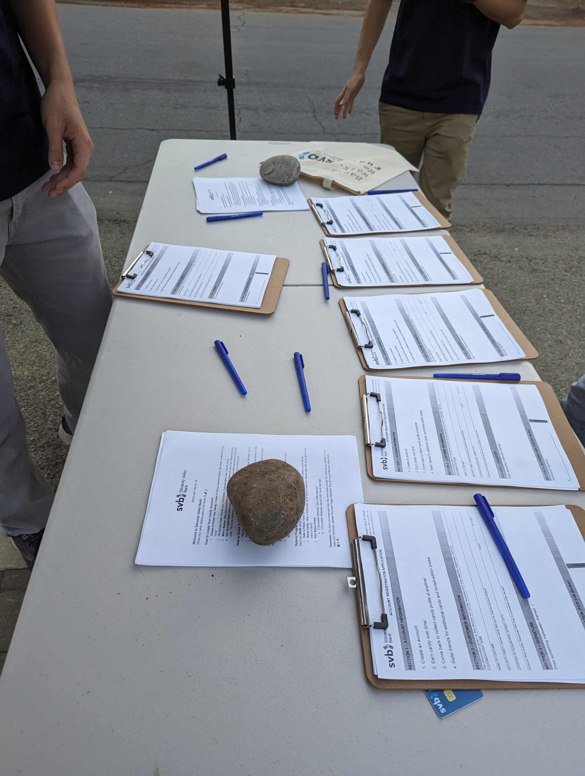
Set Design: Ticket Counter
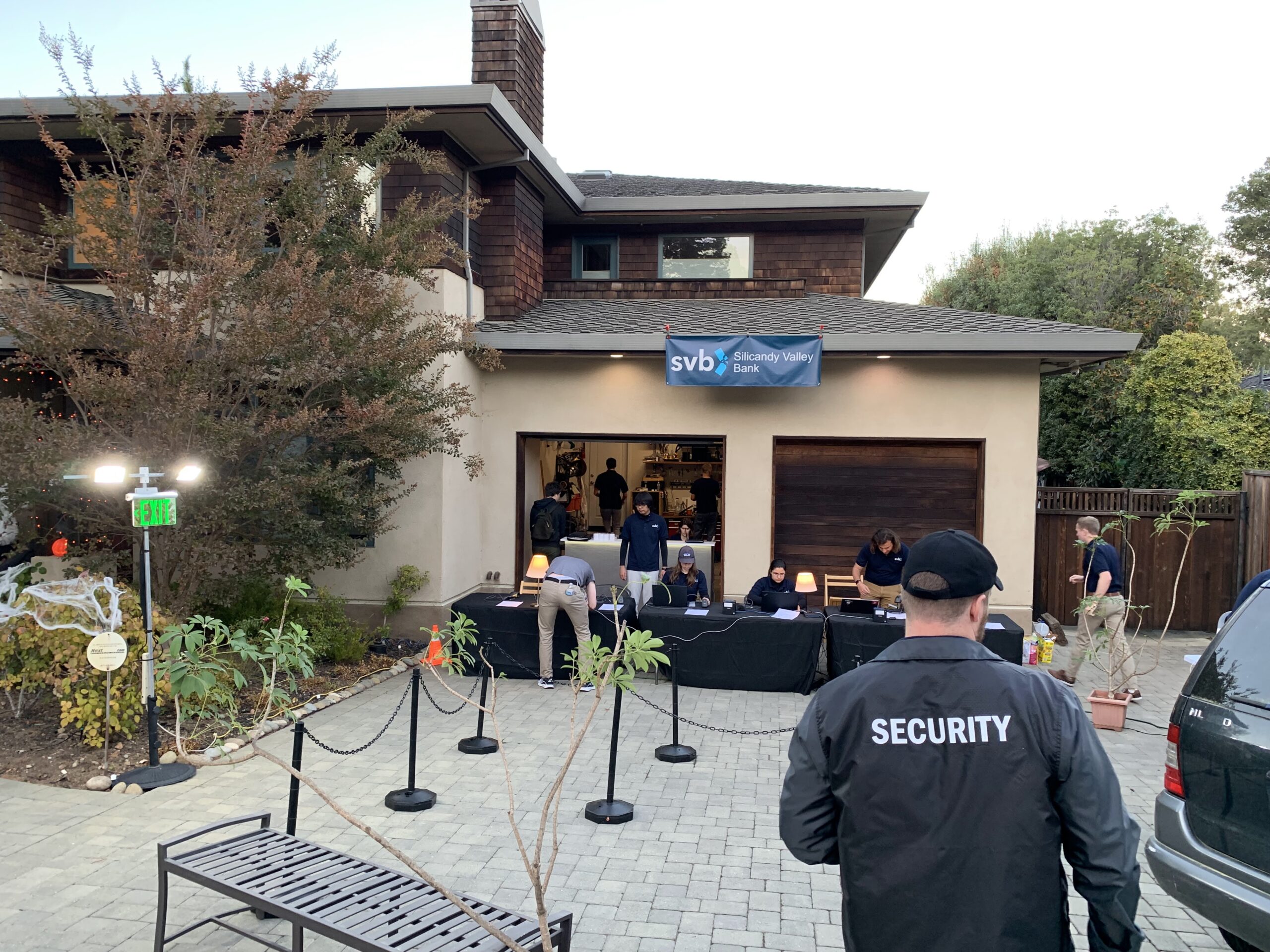
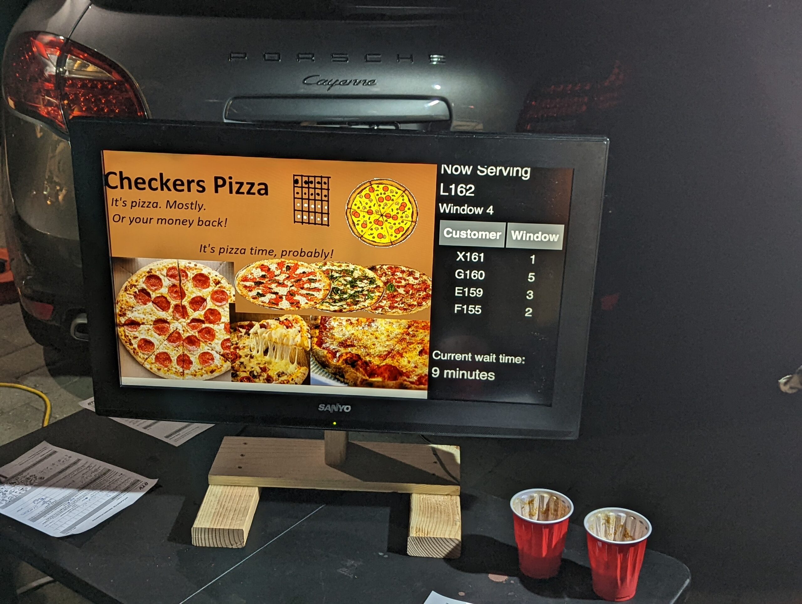
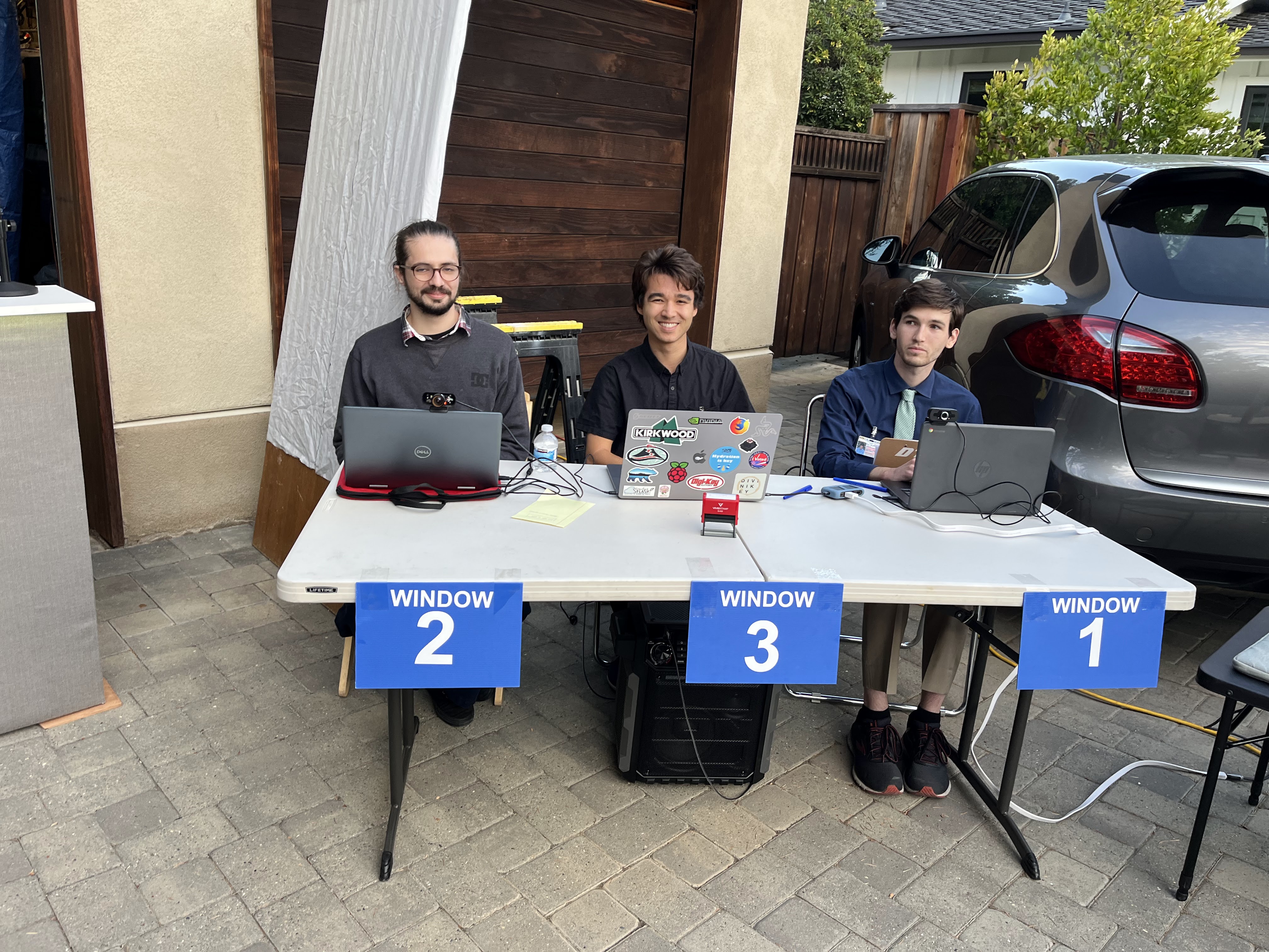
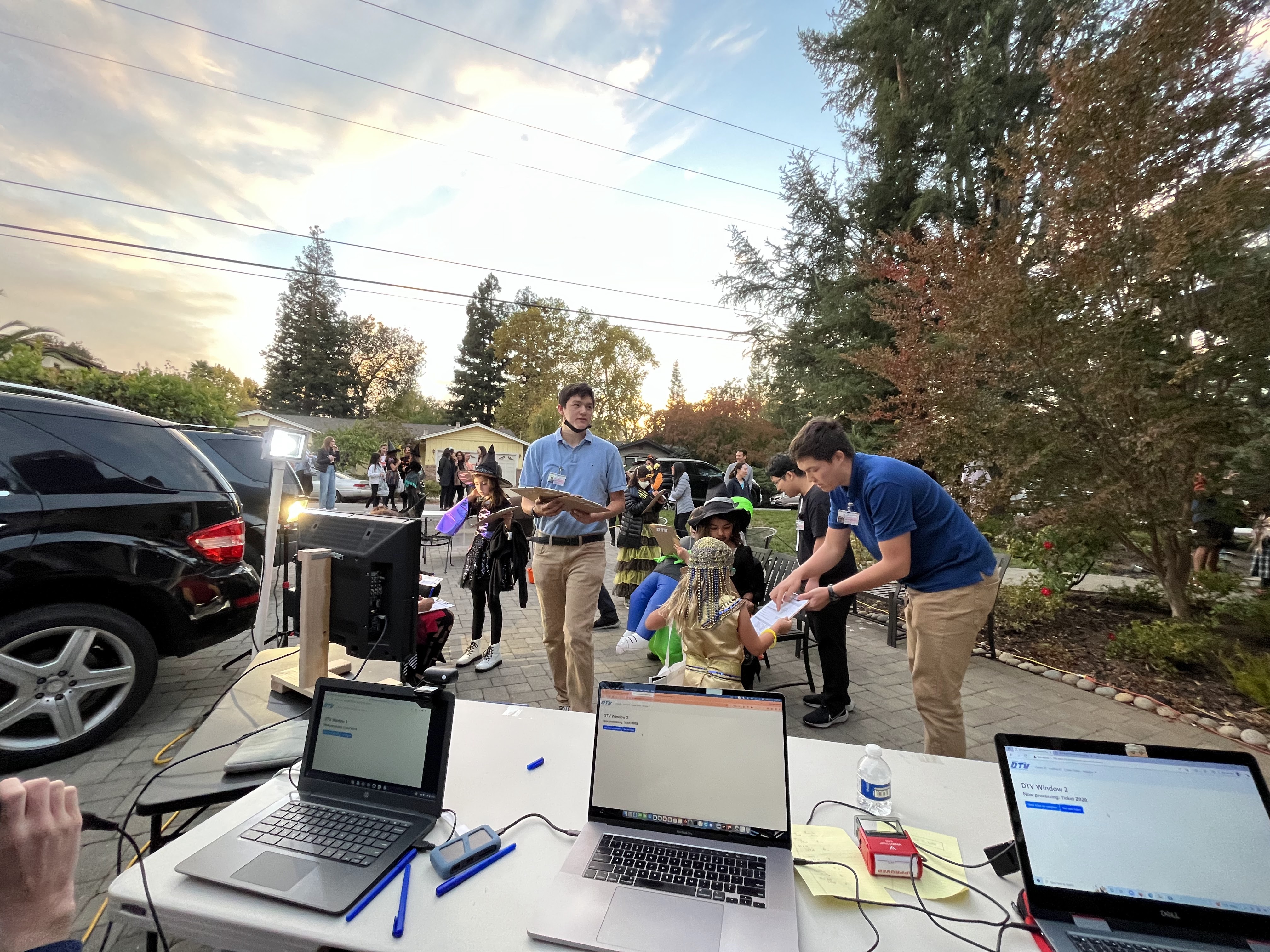
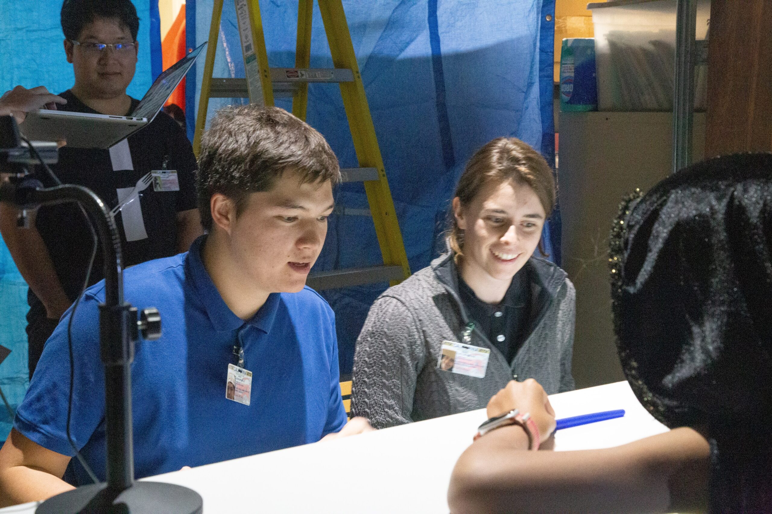
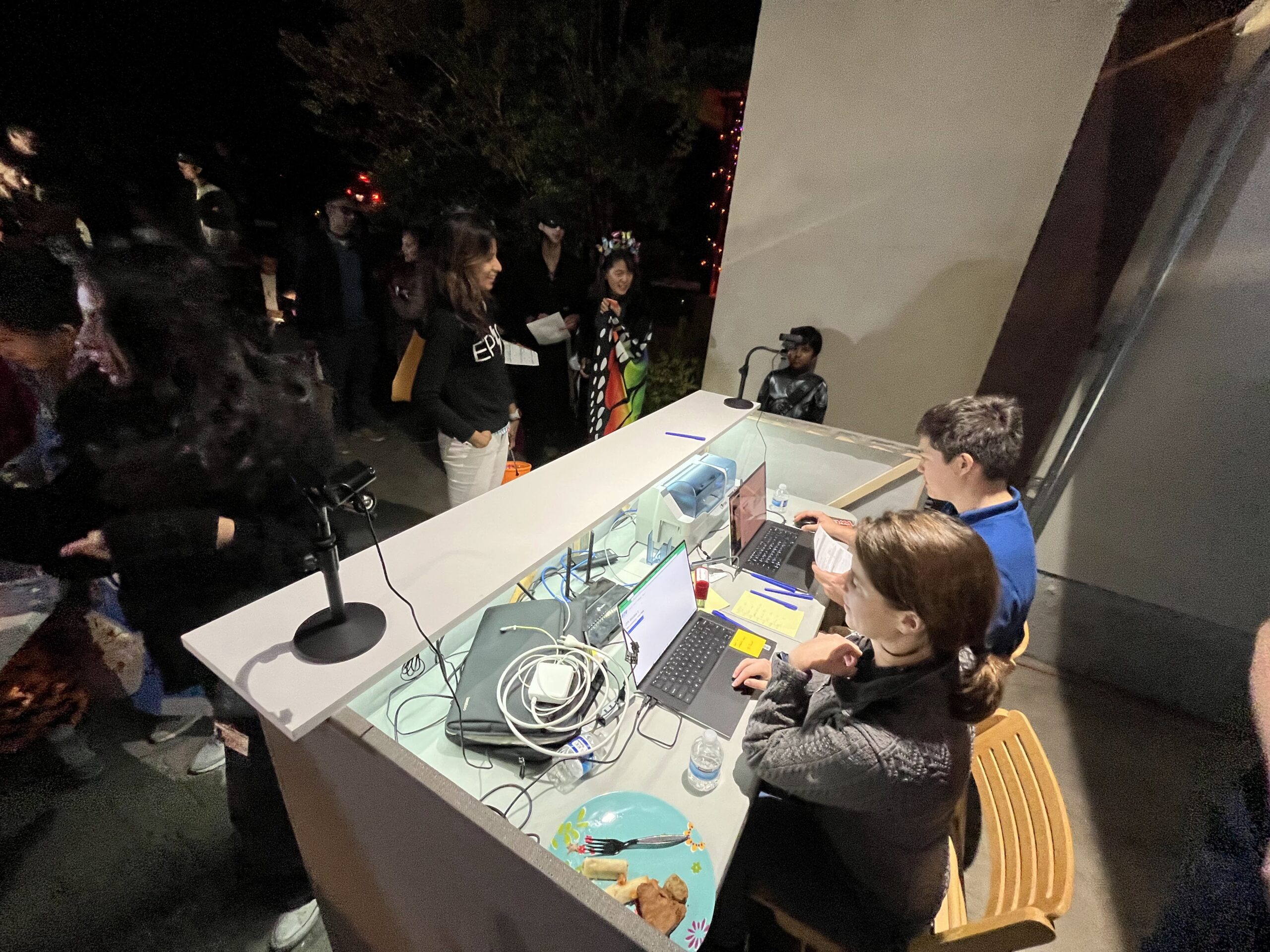
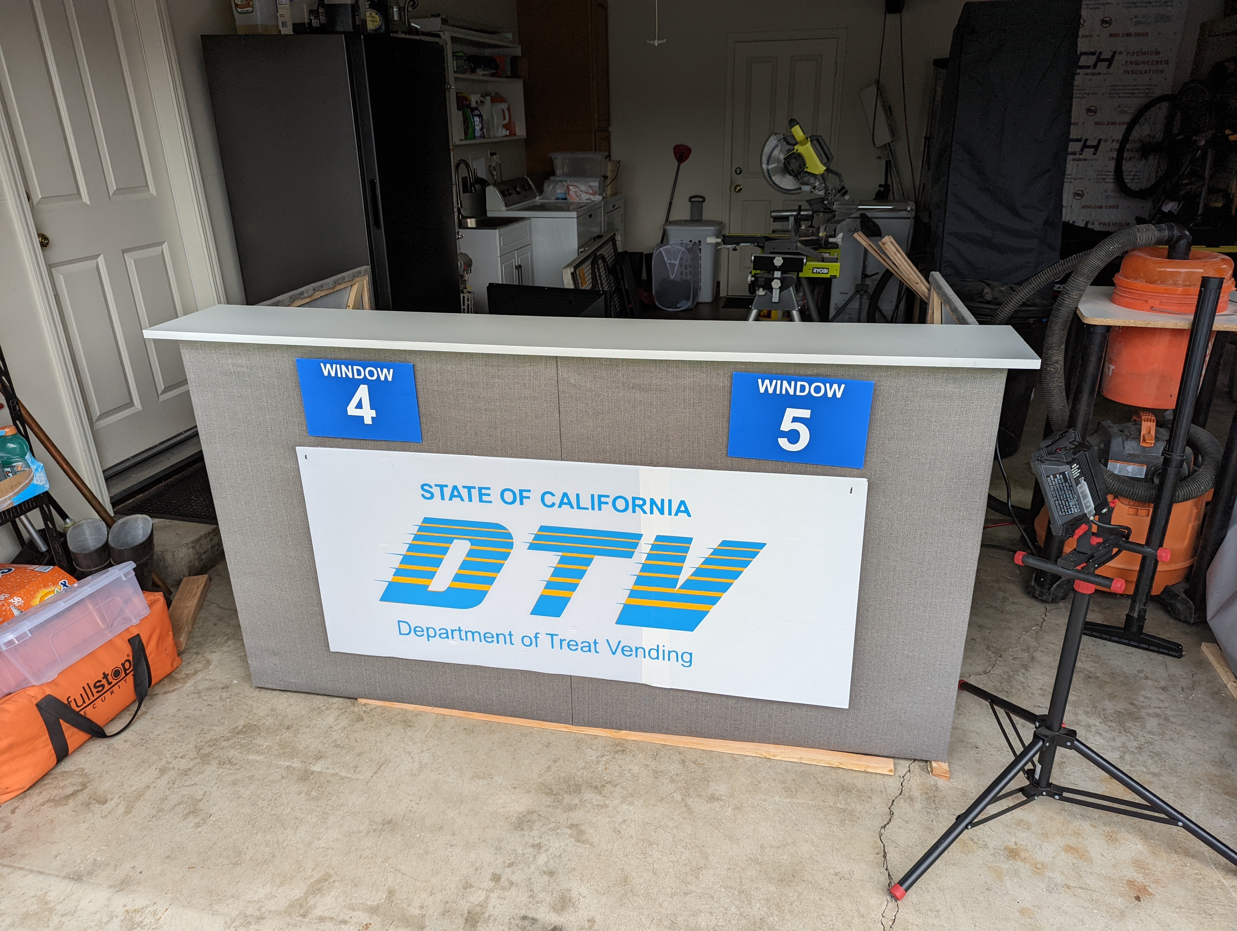
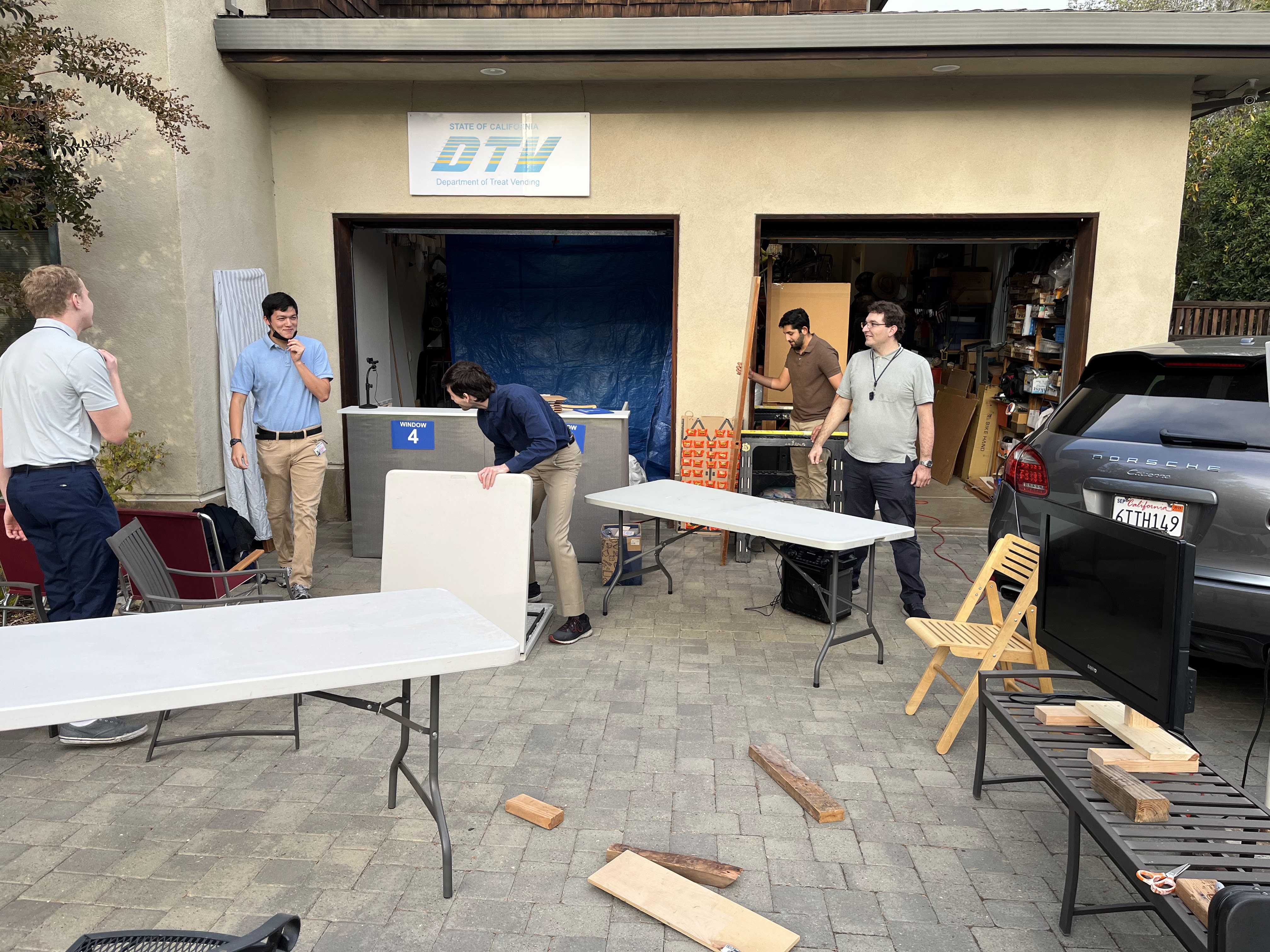
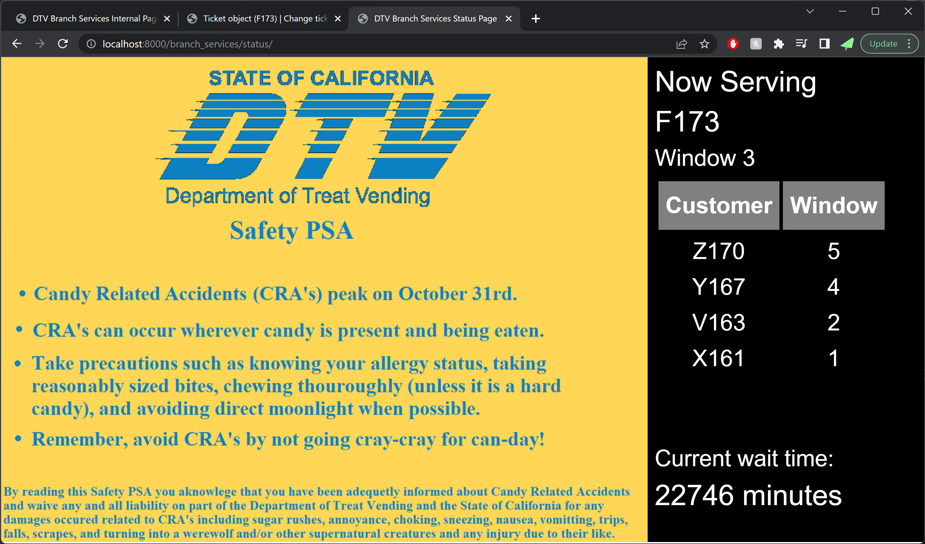
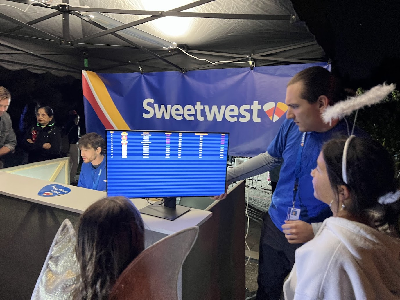
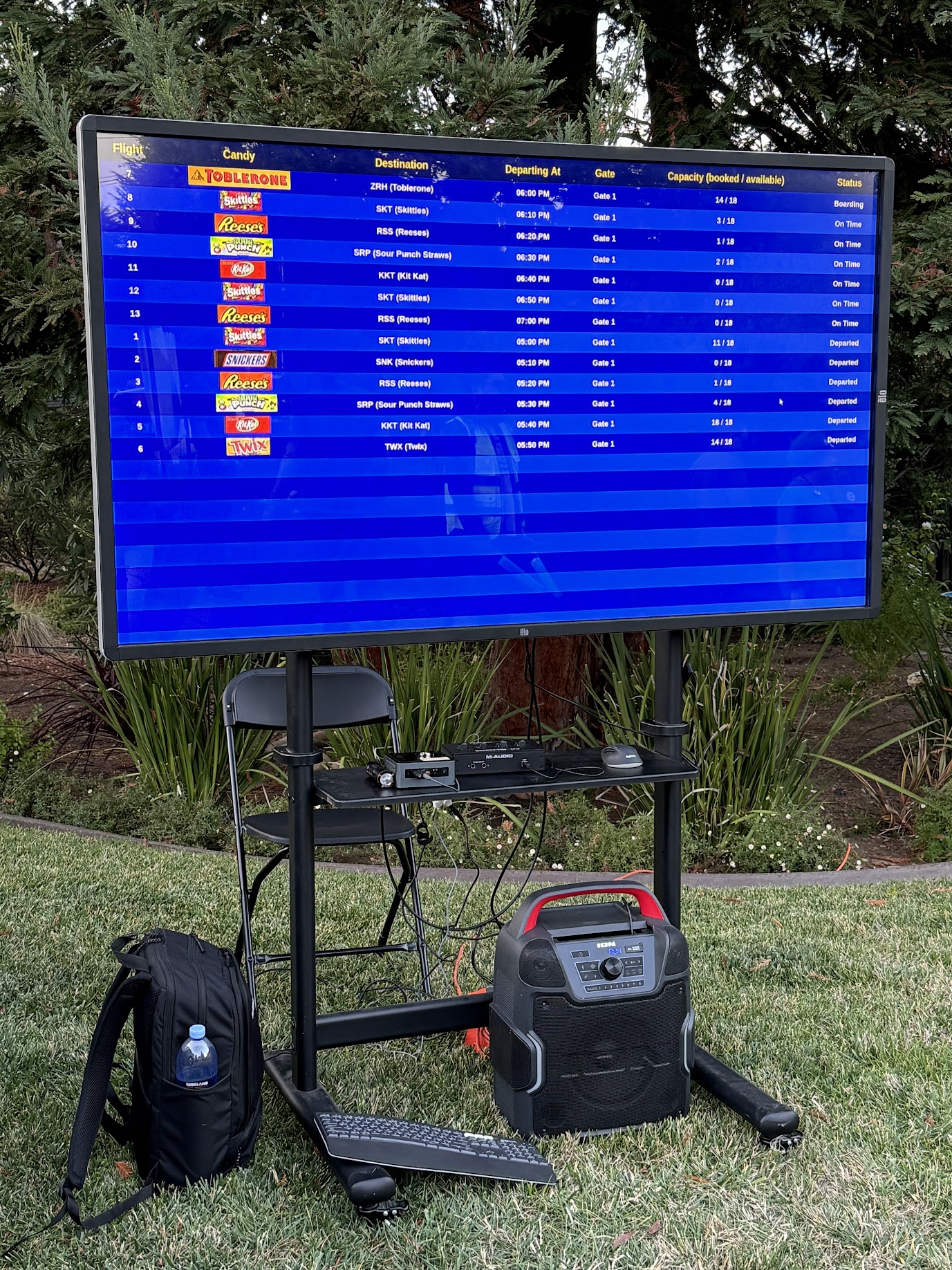
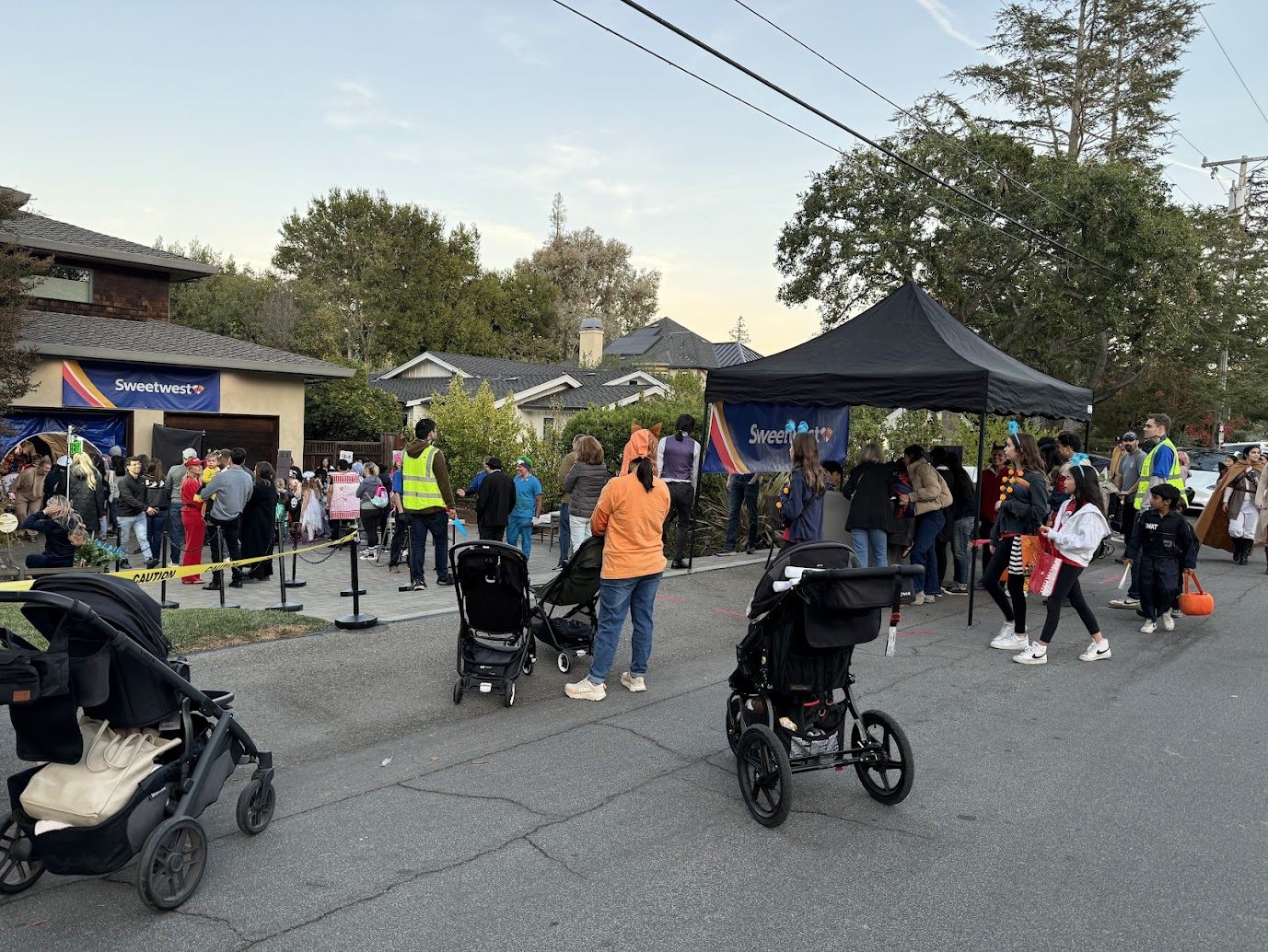
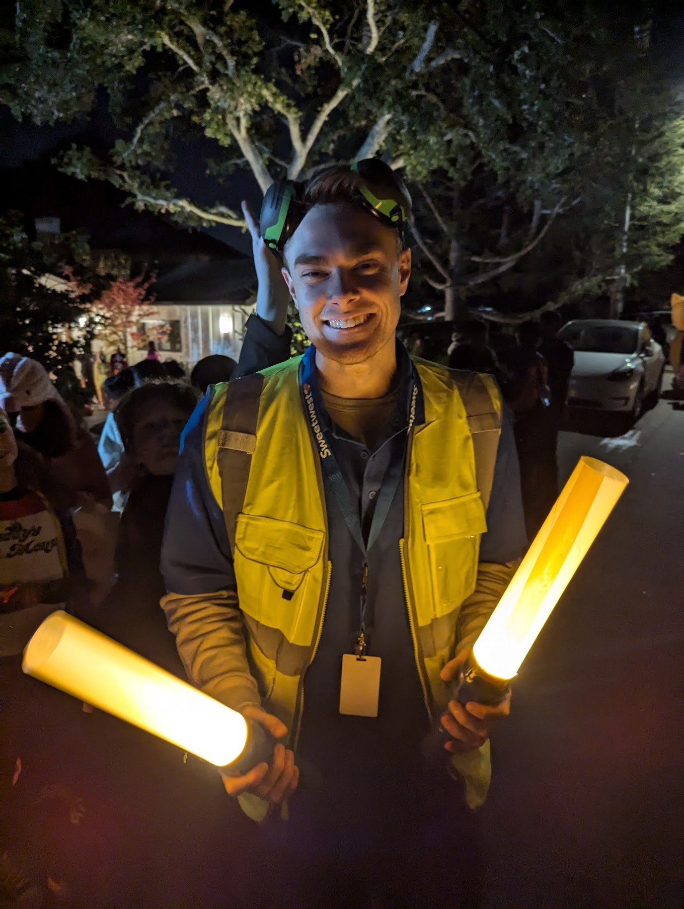
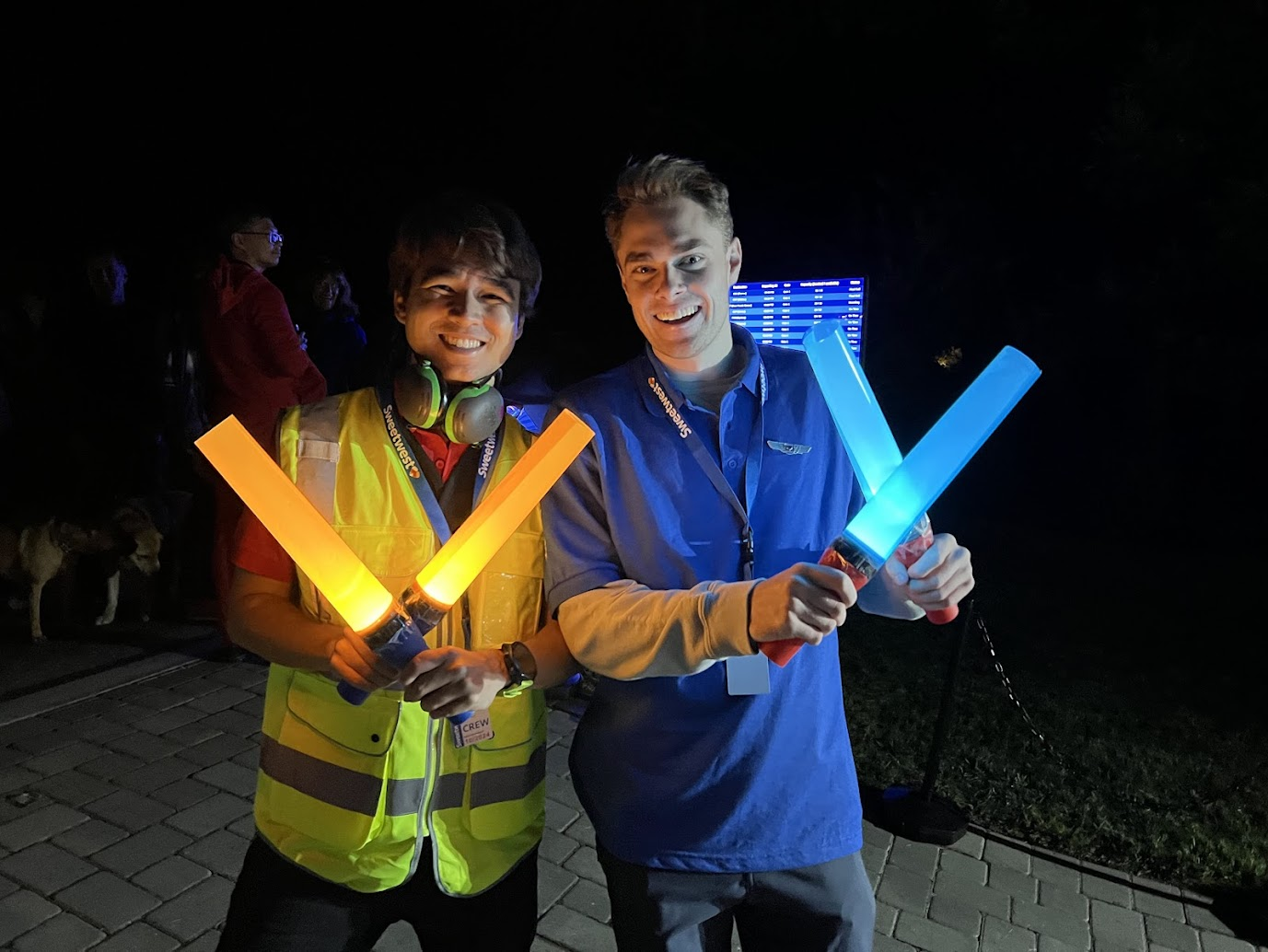
The check-in counter consisted of a 10×10 pop-up tent at the end of the driveway, with a ticket desk and Sweetwest Airlines backdrop. Sweetwest ticket agents used the IT systems built into the ticket desk to show passengers what flights were available and print out boarding passes, and helpers dressed as ramp agents with aircraft marshalling wands helped control crowds on the street and explained where tickets could be purchased. A small monitor at the end of the boarding counter showed passengers the status of upcoming flights, including their destination and departure time.
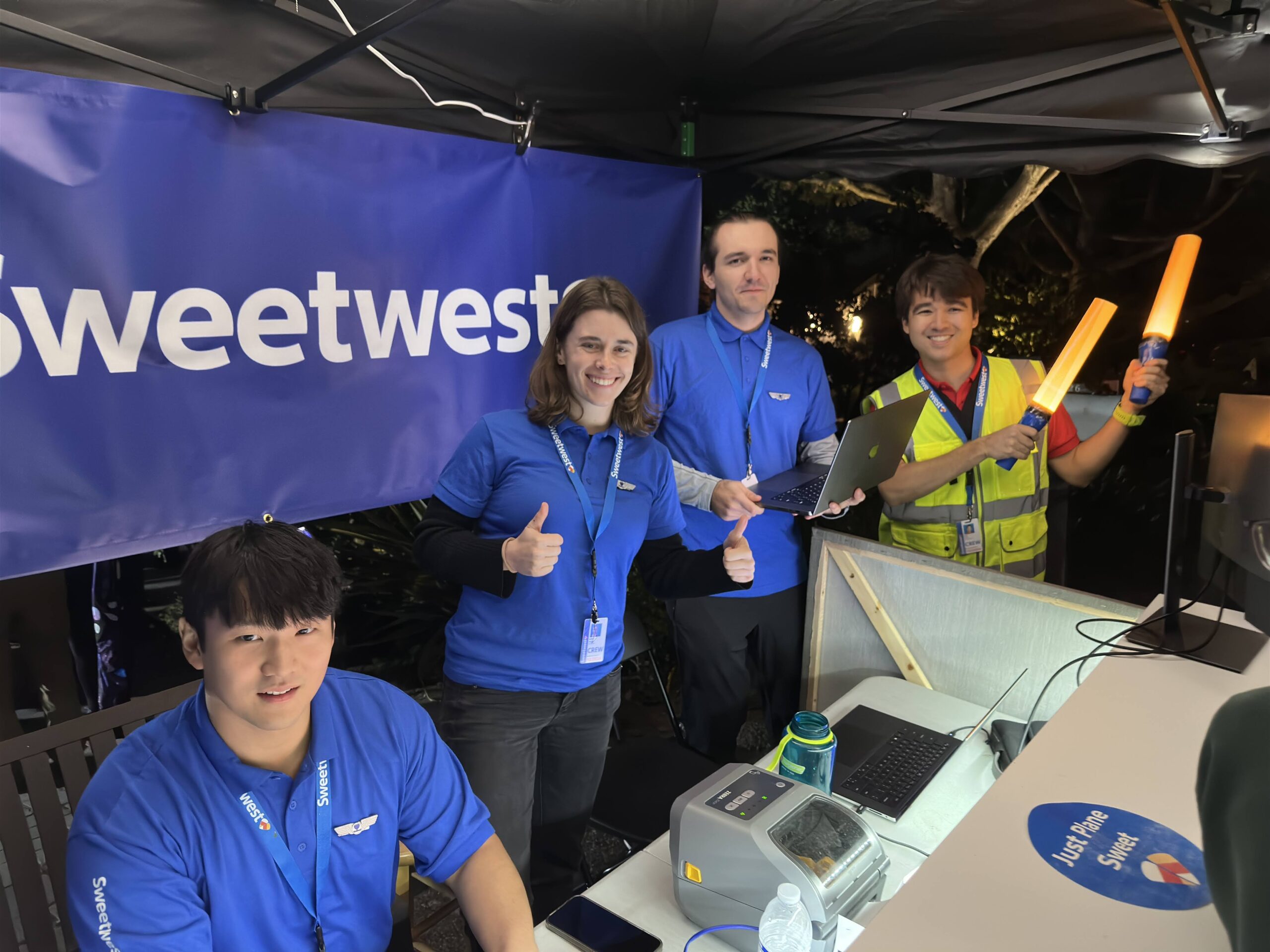
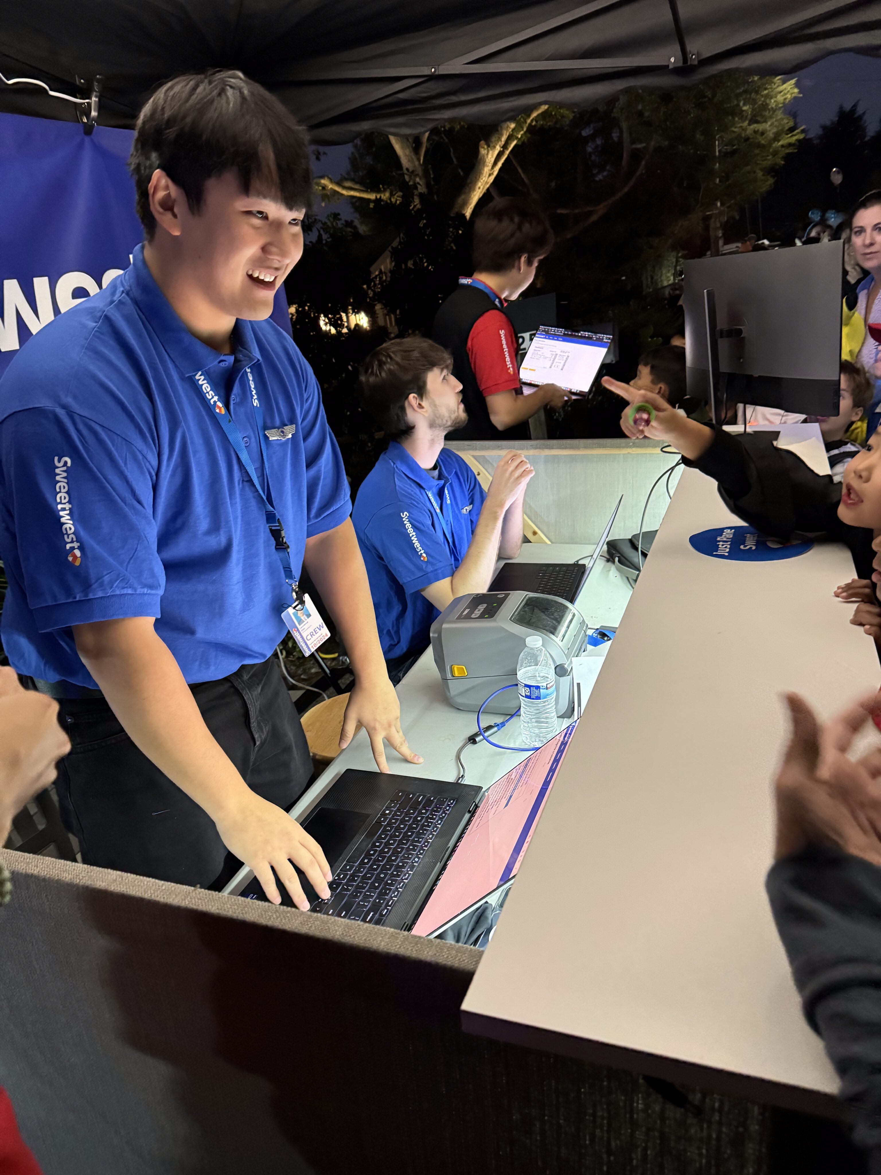
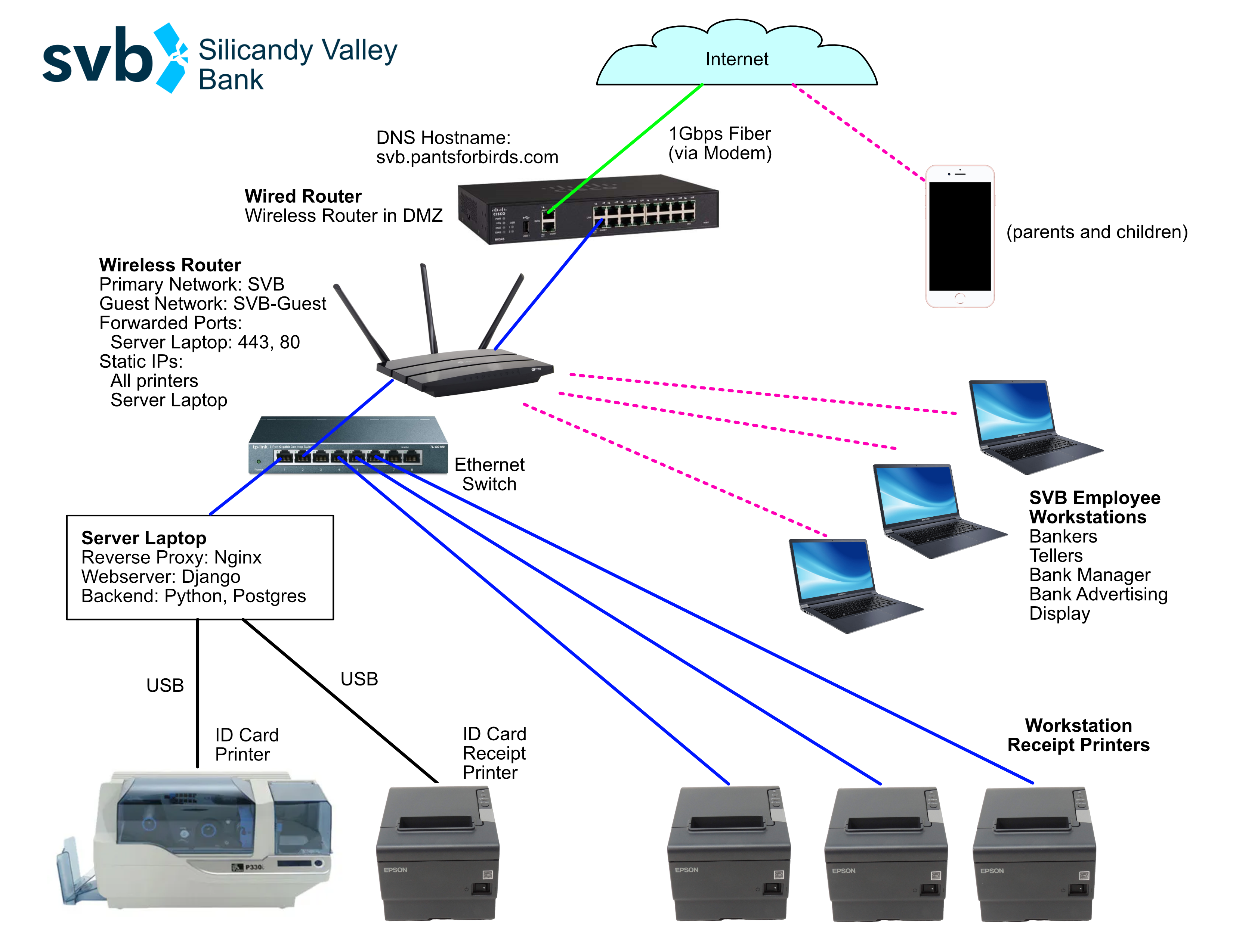
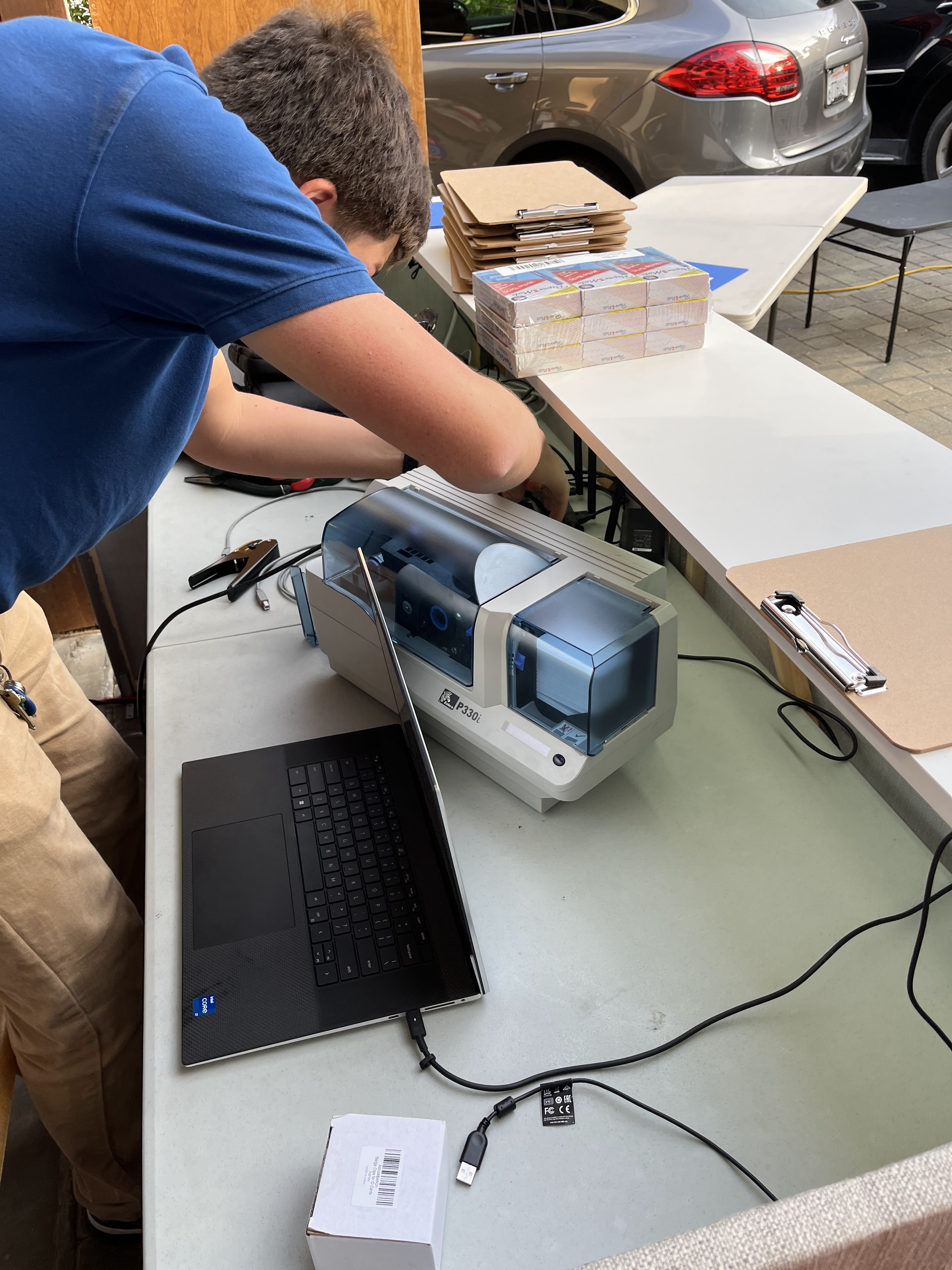
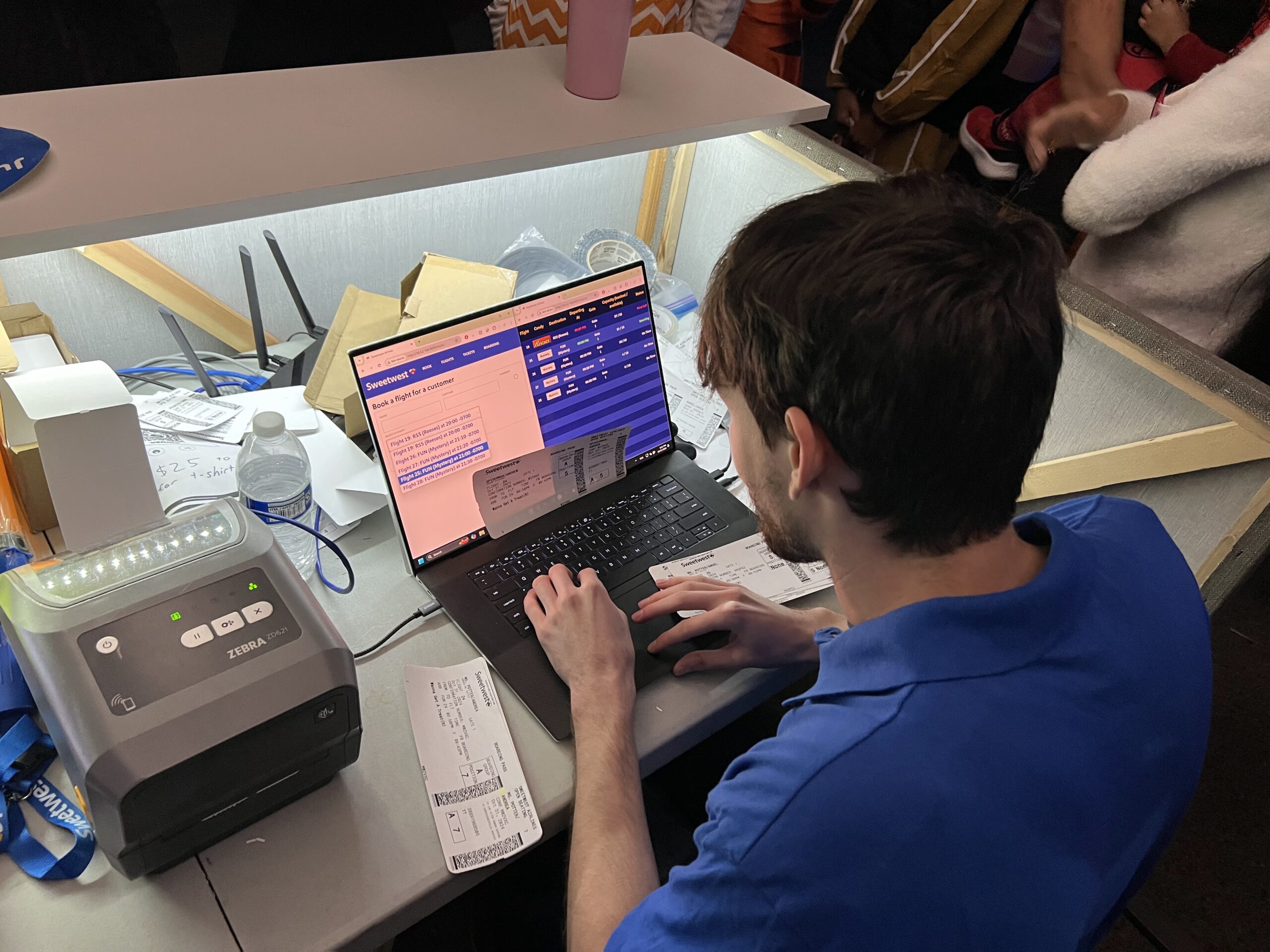
Agents at the ticket counter used laptops that were connected to the central IT system to enable them to view upcoming flights, book tickets, and print tickets. The ticket counter also served as the IT hub for the entire costume, as the router running the ethernet link to the boarding display and ticket counter, as well as the laptop running the IT system webserver, were located on the counter.
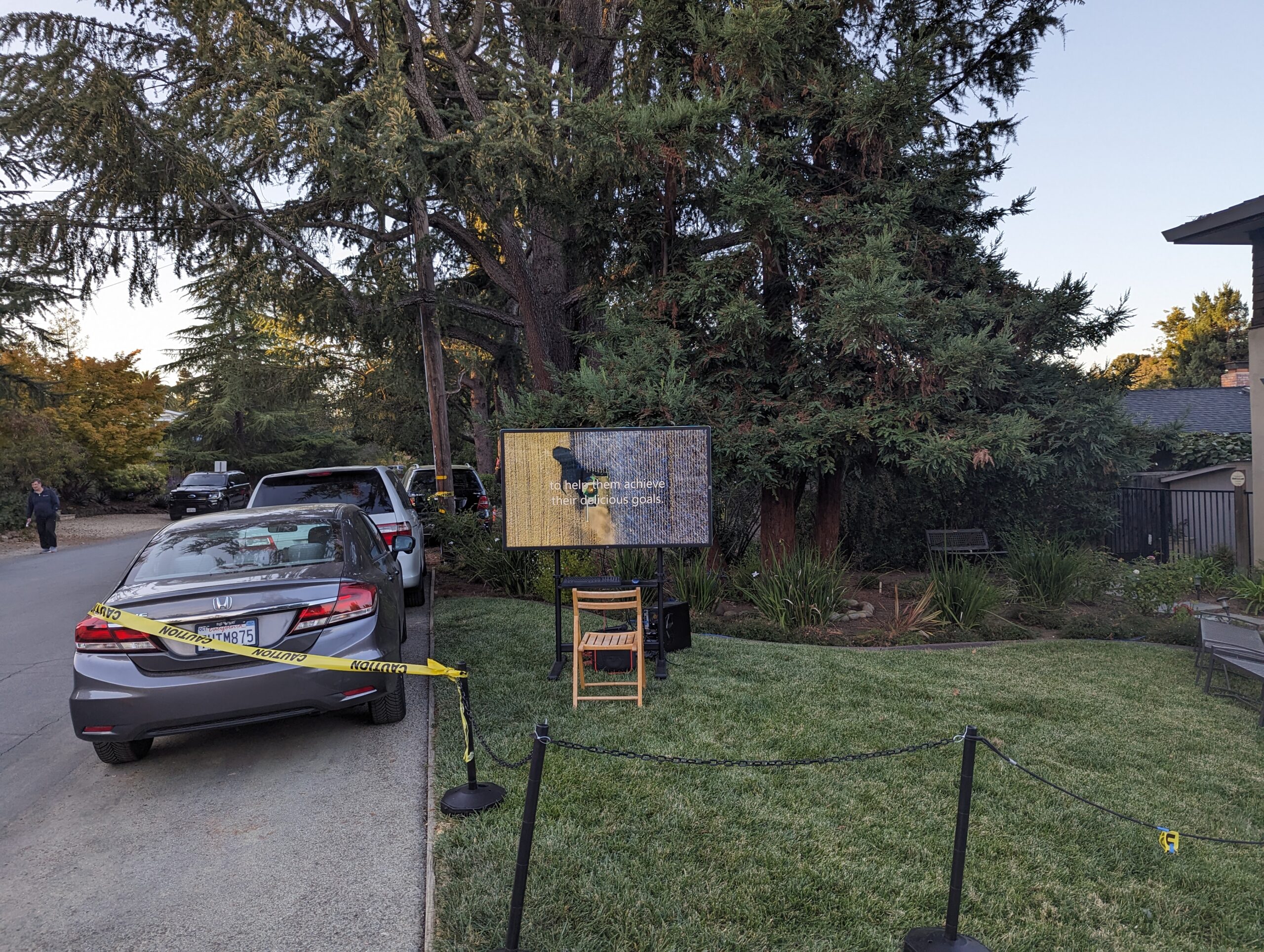
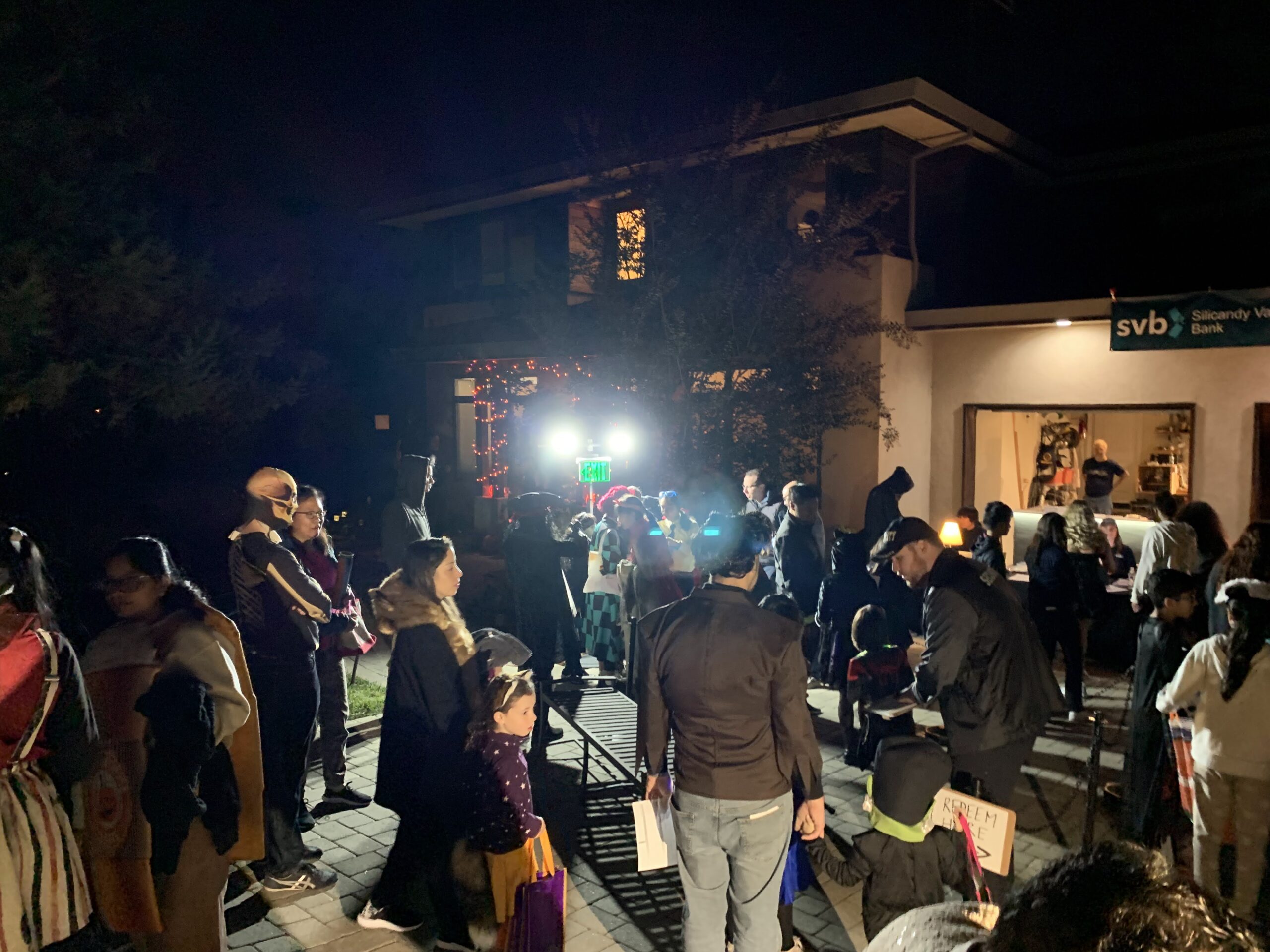
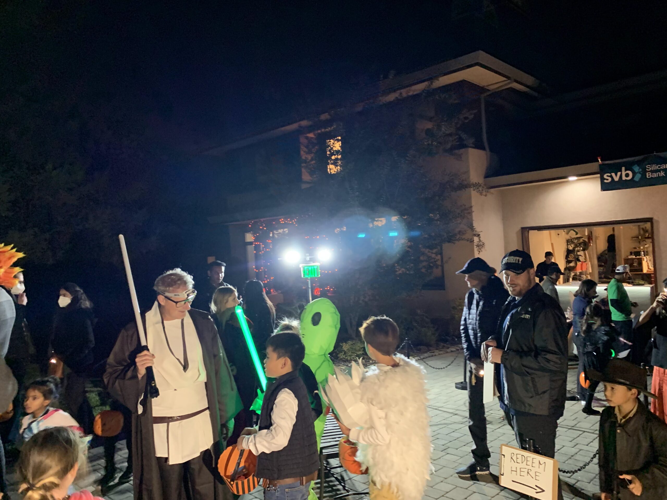
Set Design: Terminal / Waiting Area
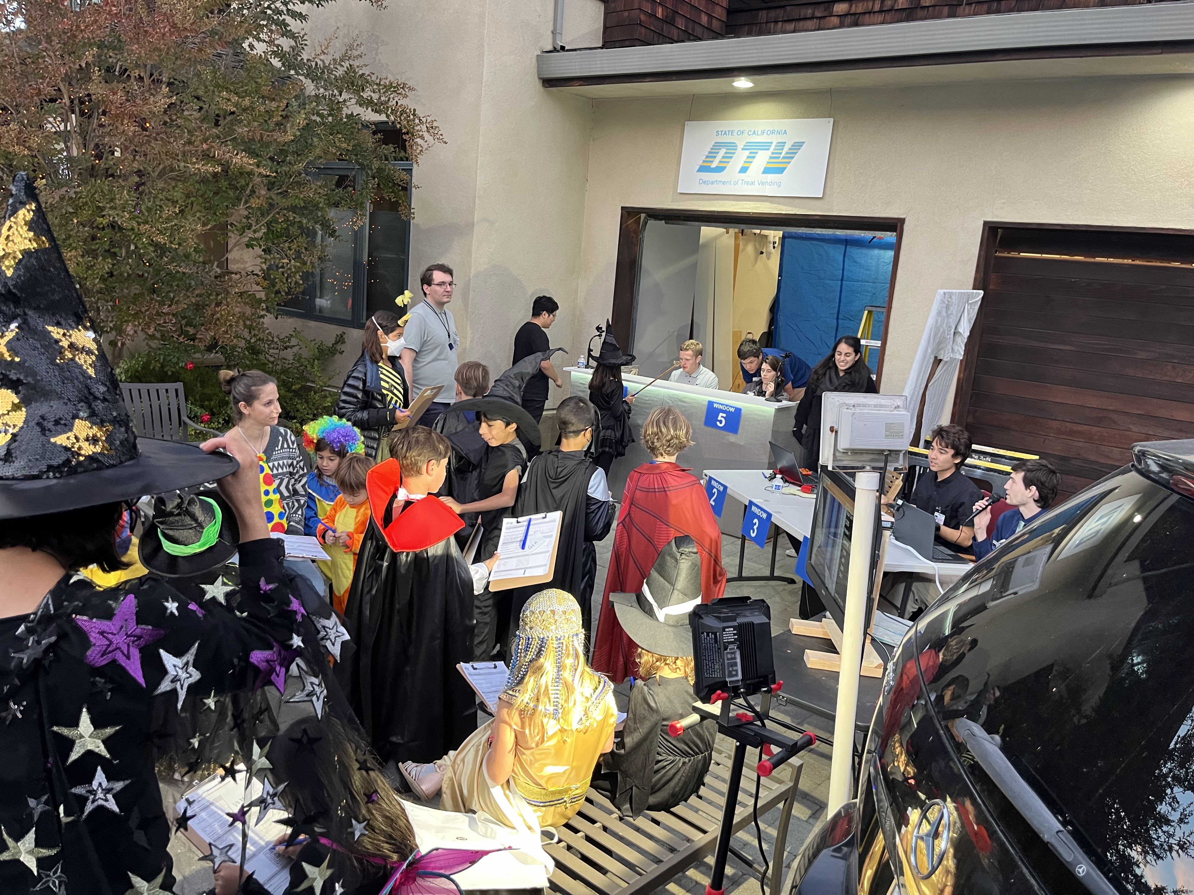
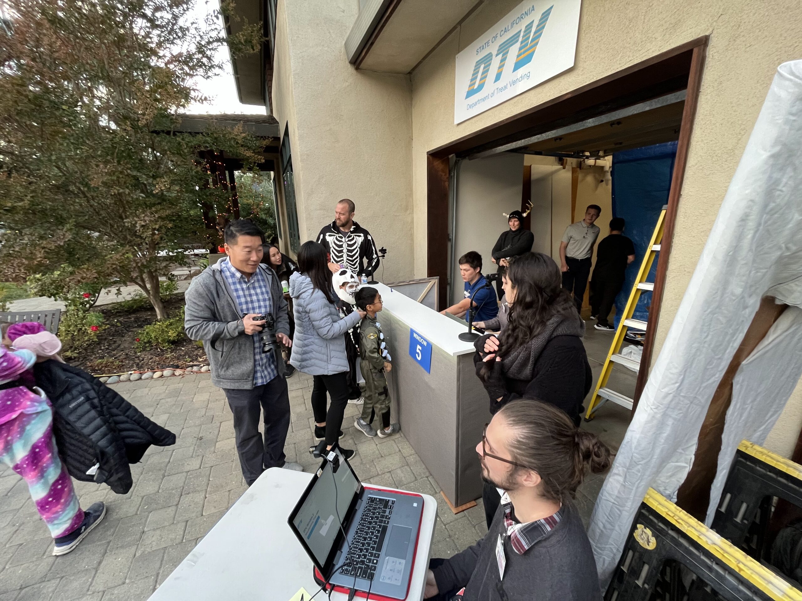
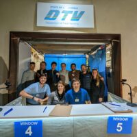
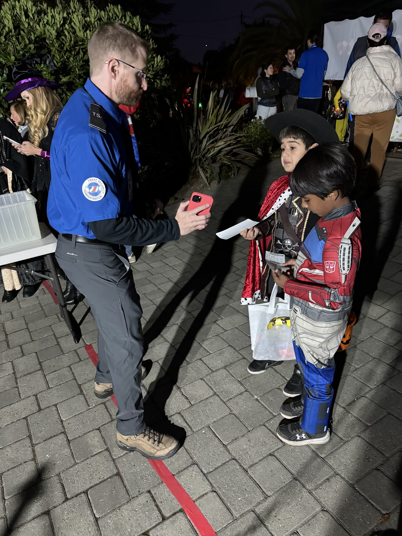
The terminal area included most of the driveway behind the ticket counter, as well as a portion of the lawn to the left of the driveway. A large monitor was used to display flight information, and a custom audio system was developed to provide terminal announcements (with trademark bing-bong audio cues and purposeful audio enshittification to emulate a terminal PA system). With the quantity of moving parts already in play, we decided against setting up the full-fledged TSA checkpoint we had built a few years back, and instead had two Treat Security Agents that passengers needed to interact with before passing into the secure waiting area. Our Treat Security Agents performed their jobs admirably, ensuring that all passengers entering the boarding area had valid boarding passes and understood the boarding process. Thanks to their dedicated efforts, the number of Confused Passengers was greatly reduced, and there were zero attempted aircraft hijackings for the duration of the evening.
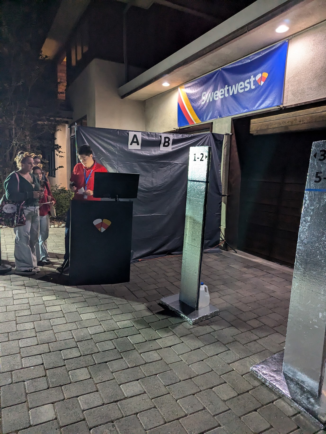
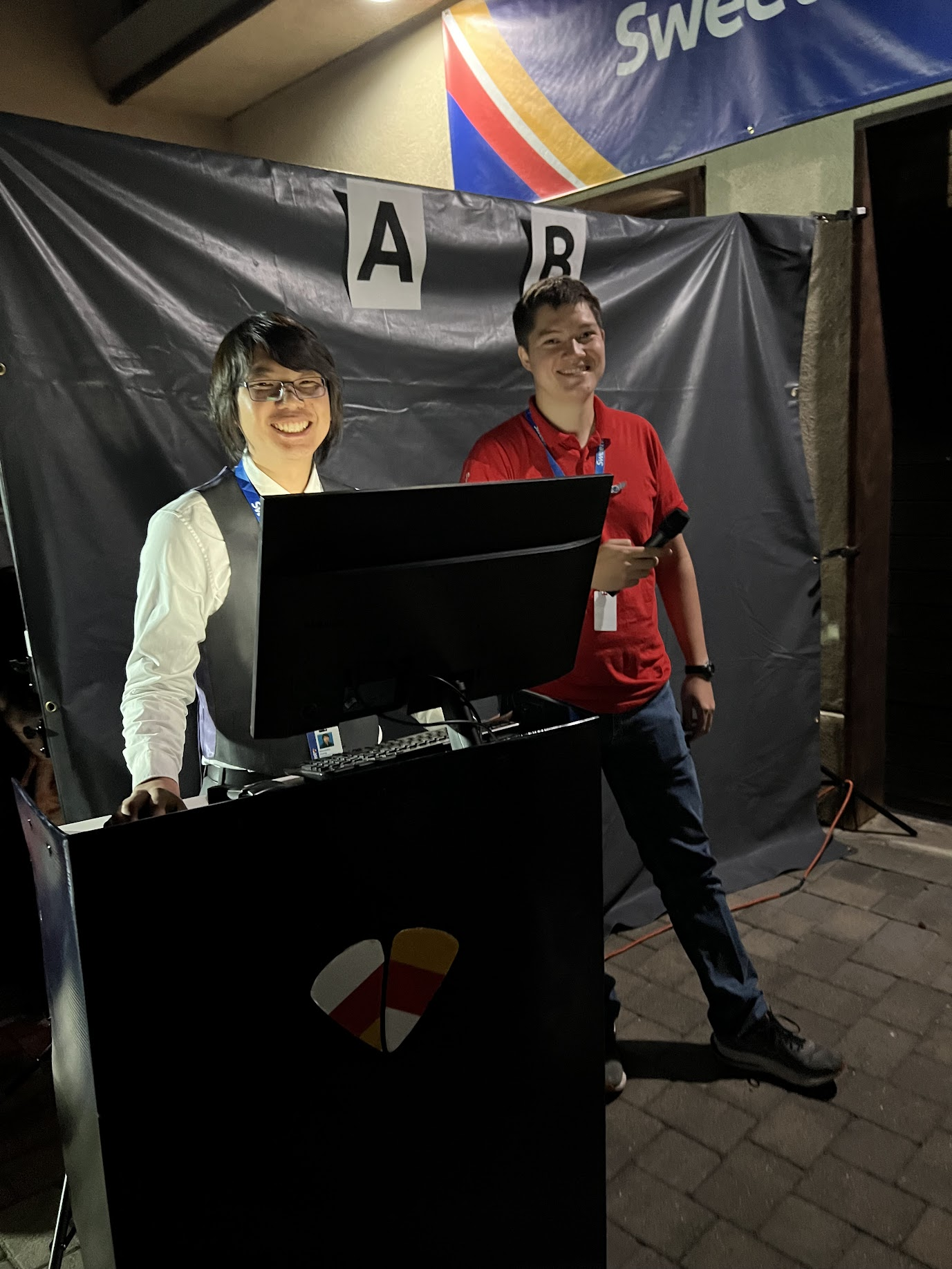
Set Design: Boarding Gate
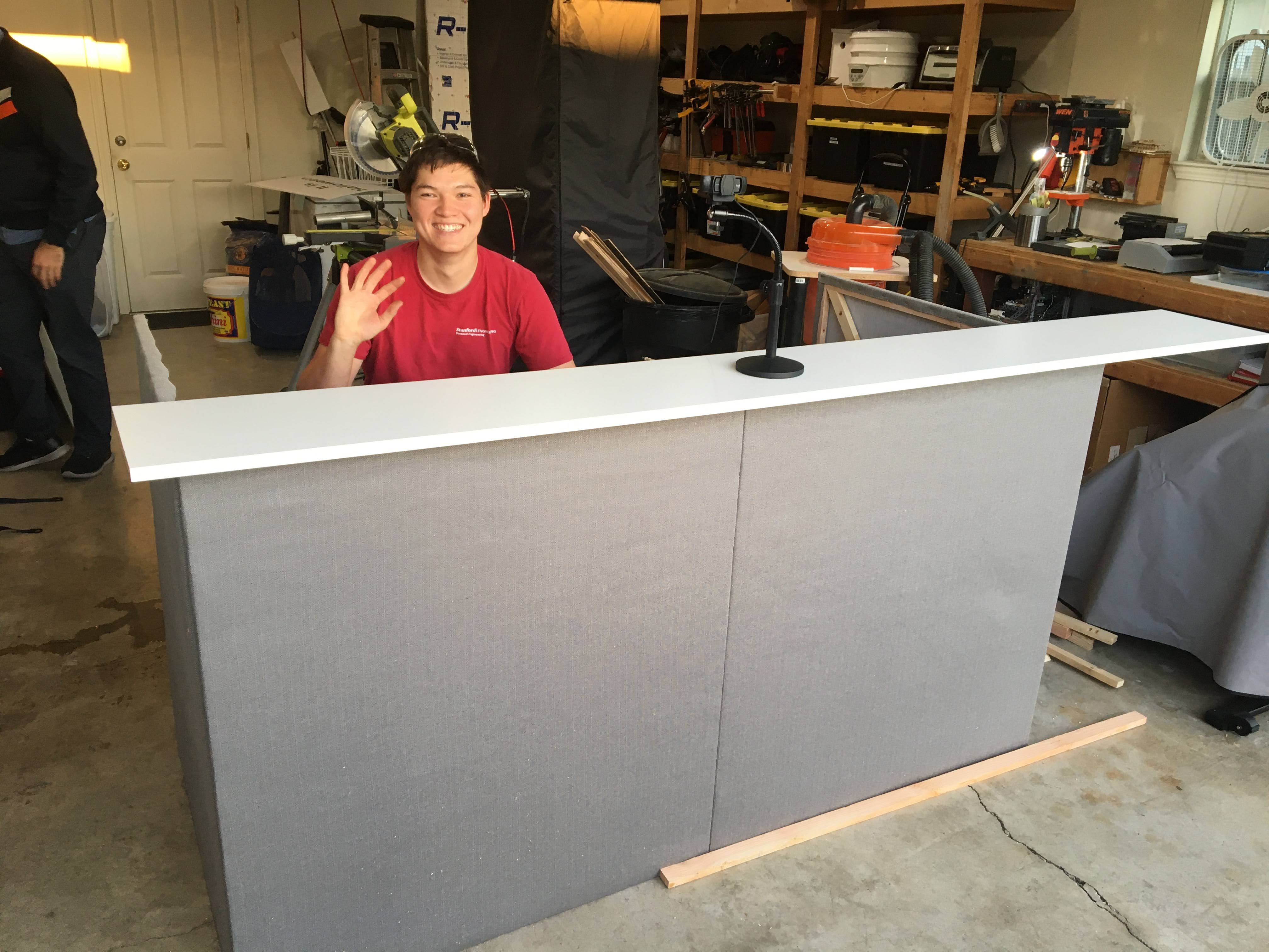
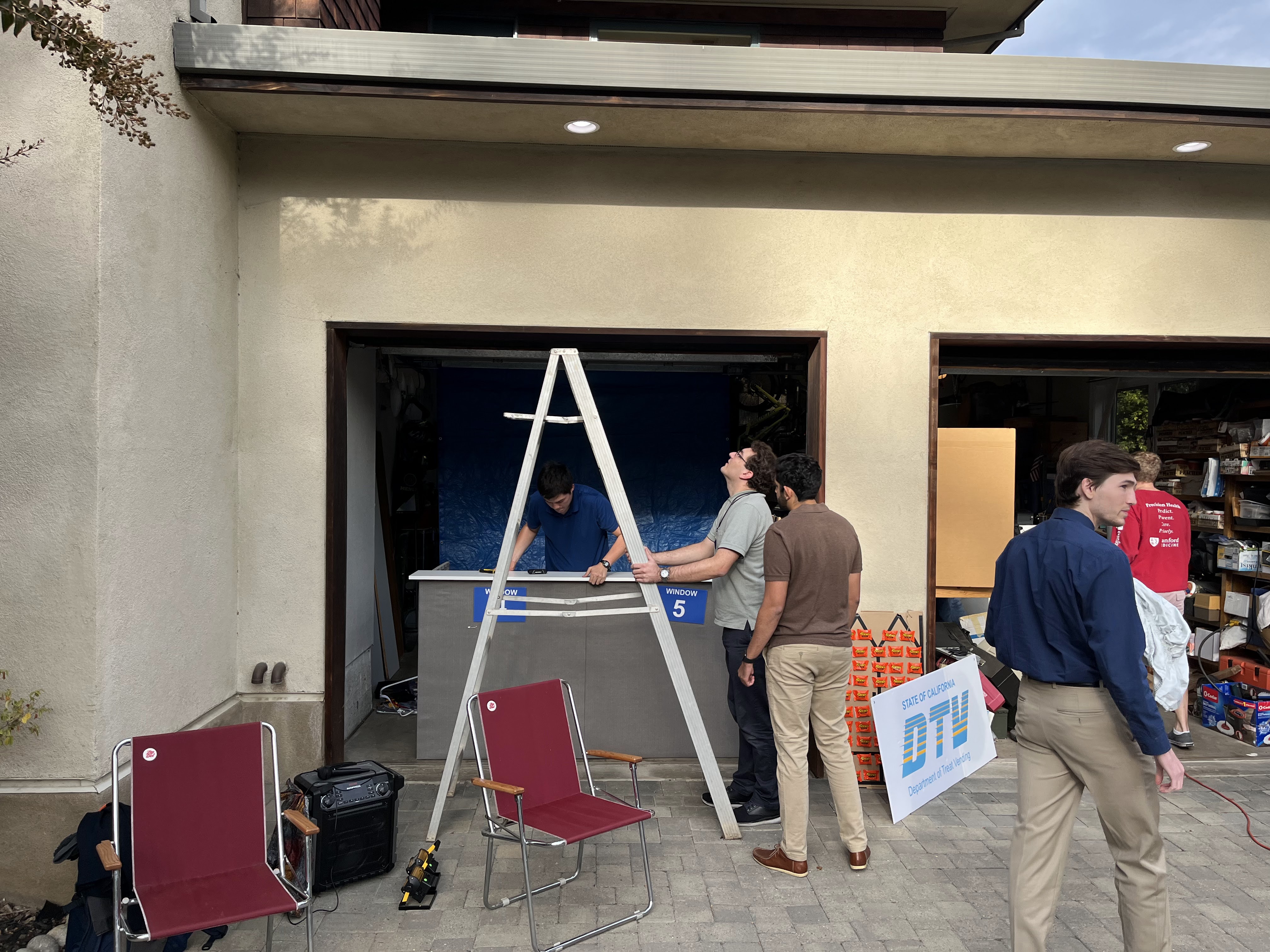
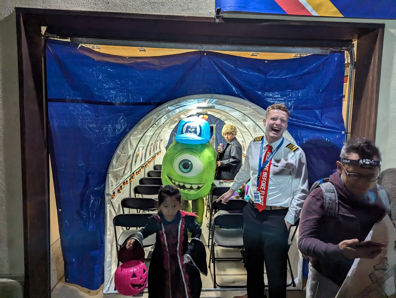
The boarding gate was designed to emulate a standard Southwest Airlines airport gate with as few materials as possible. In addition to providing a place for the Boarding Experience™, the gate served to corral passengers and provide some semblance of separation between the aircraft and the airport (primarily through the liberal use of a large tarp and a wonderfully absorptive blob of parents pulling double duty as sound insulation for passengers in the aircraft).
While planning the set design, we realized that there were a few important components to the Boarding Experience™ that we needed to capture.
- Waiting for boarding to begin, only to realize that they are boarding a different group.
- The slight air of superiority emanating from people in said group as they walk past you.
- Southwest specific: finding your spot in line next to the numbered boarding pillars. “Are you 54? I’m 53.” (apologetic)
- The barcode scanner that needs to scan everyone’s boarding pass, but refuses to scan every fifth pass until the gate agent tries one more time.
- Loud airport announcements, including boarding calls and final calls for specific passengers that are stuck in line at Starbucks or about to miss their flight in another manner.
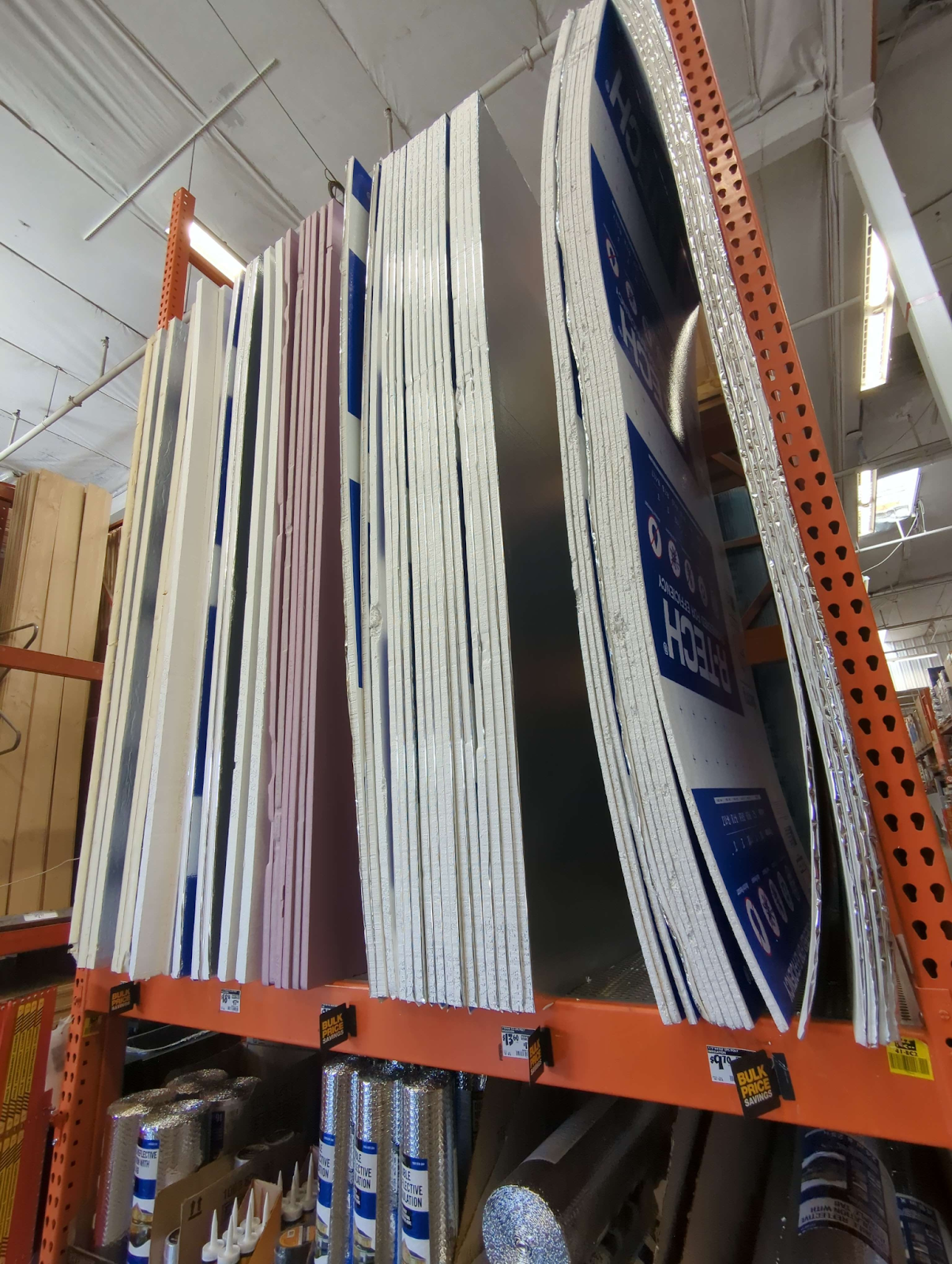
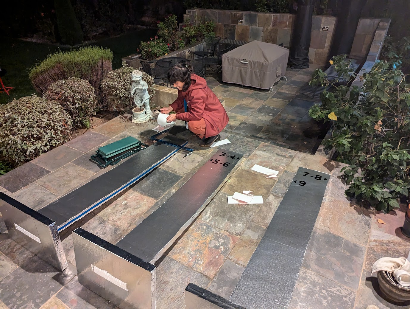
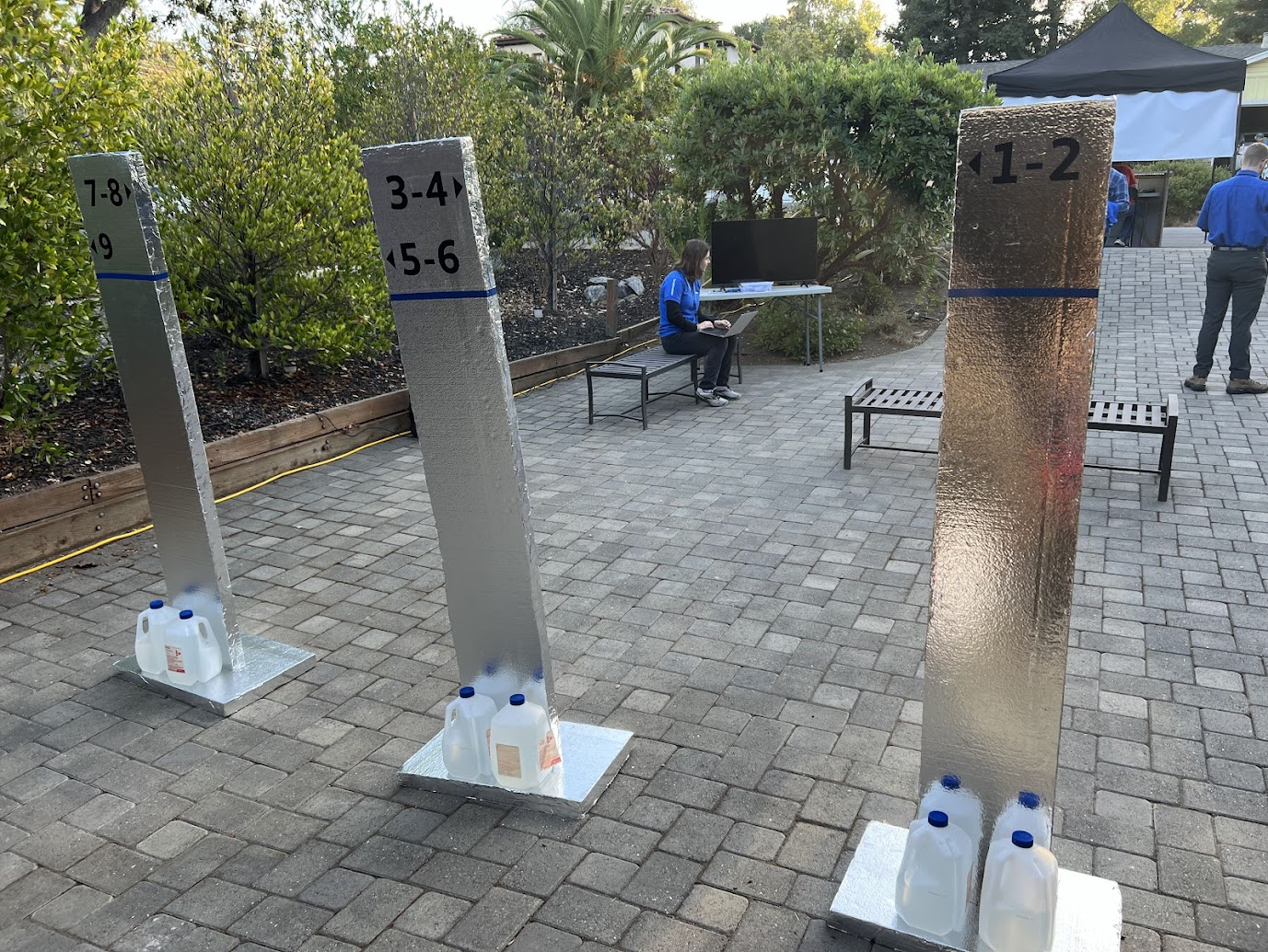
These goals were readily accomplished with the fabrication of a few set pieces. For the boarding pillars, we needed something cheap and light enough that it wouldn’t hurt anyone if it fell over. Gluing some foil-backed insulation foam sheets together (shiny side out) turned out to be perfect for this, and adding the blue accents (electrical tape) and numbering (black vinyl) was a breeze. We did encounter an issue with the pillars tipping over too easily, but this was remedied with the addition of some gallon jugs of water at the base of the pillars.
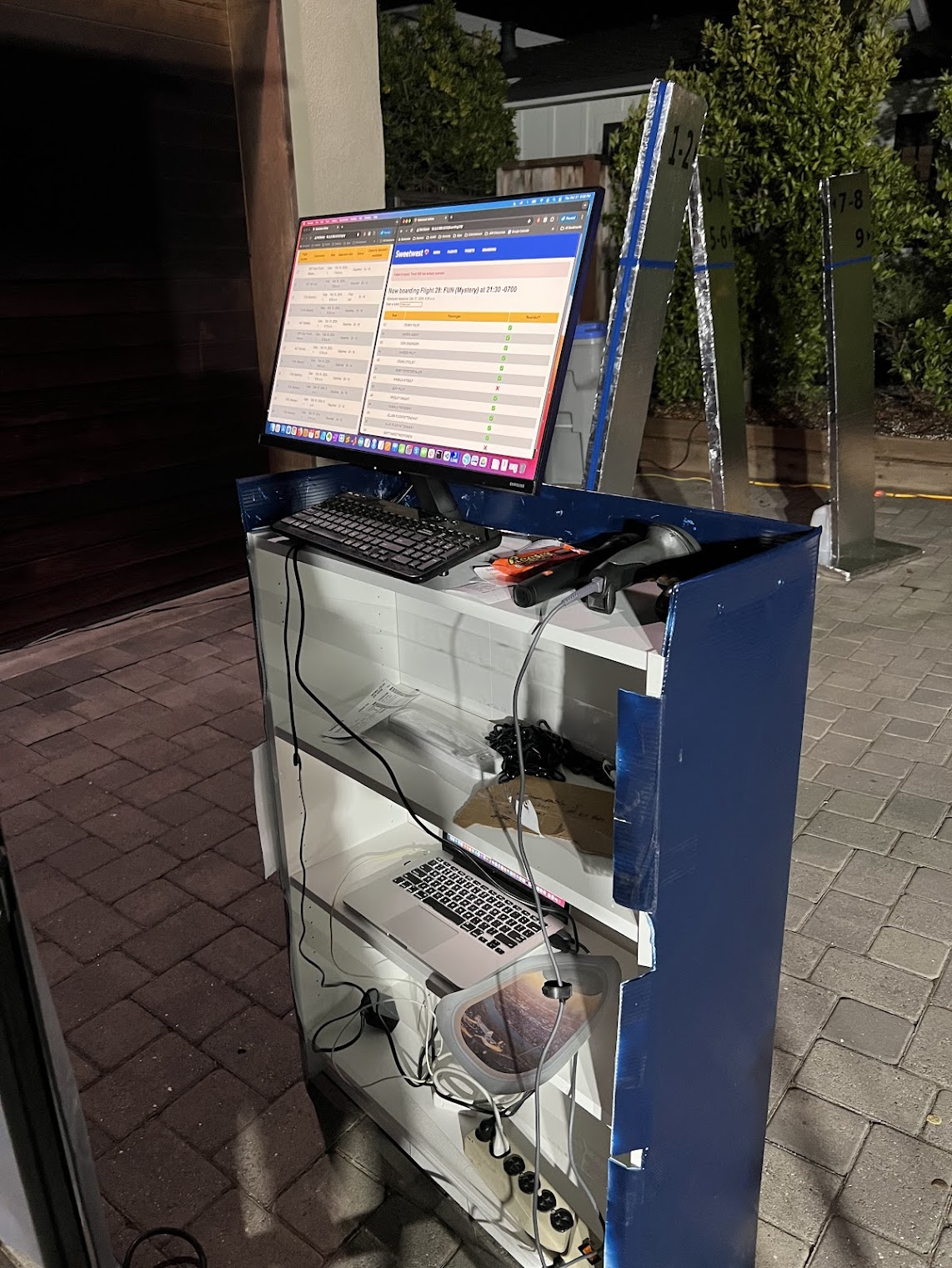
For the boarding podium, we wrapped an IKEA bookshelf in painted coroplast, and added a Sweetwest Airlines logo cut out of paper. The gate agent was provided with a laptop and a barcode scanner that was capable of reading PDF417 barcodes. Importantly, the barcode scanner provided was purchased from eBay as “Parts Only – Not Working”. It scanned codes just fine, but with a reliability rate of around 80%–perfect.
Gate announcements were made over the airport PA system (more details on this later), letting passengers know when flights were beginning to board, when the next boarding group was being called, which passengers were missing, and when flights were departing.
Here’s another closeup of the boarding counter, including the ancient Macbook being used to run it, and a window that fell off of the airplane. It fell off during a flight–we shrugged and said “it’s a Boeing”. People laughed, people ate candy, we reattached the window with spray adhesive. Good times.
Set Design: The Airplane
Since we didn’t have 120 million dollars on hand for an actual Boeing 737, we had to get creative while designing a set for the in-flight experience portion of the costume. We had a few key design criteria for the aircraft:
- Fits into a single car garage.
- Seats 16 passengers.
- “Feel like” an airplane (can’t just be some tape on the ground).
- Allows parents to have direct line of sight to their children (e.g. can’t close the garage door).
- Wide enough aisle to allow food service with a cart.
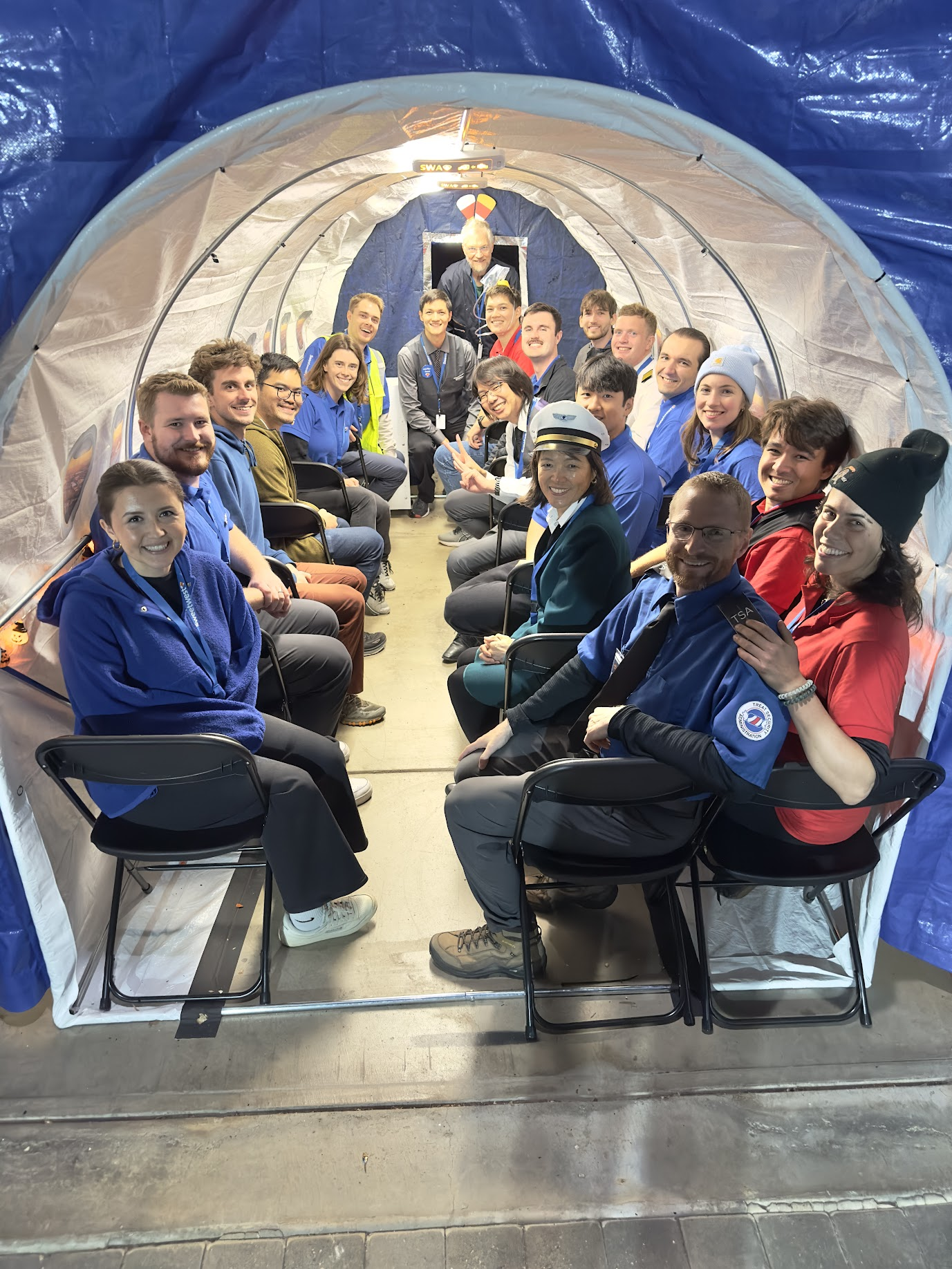
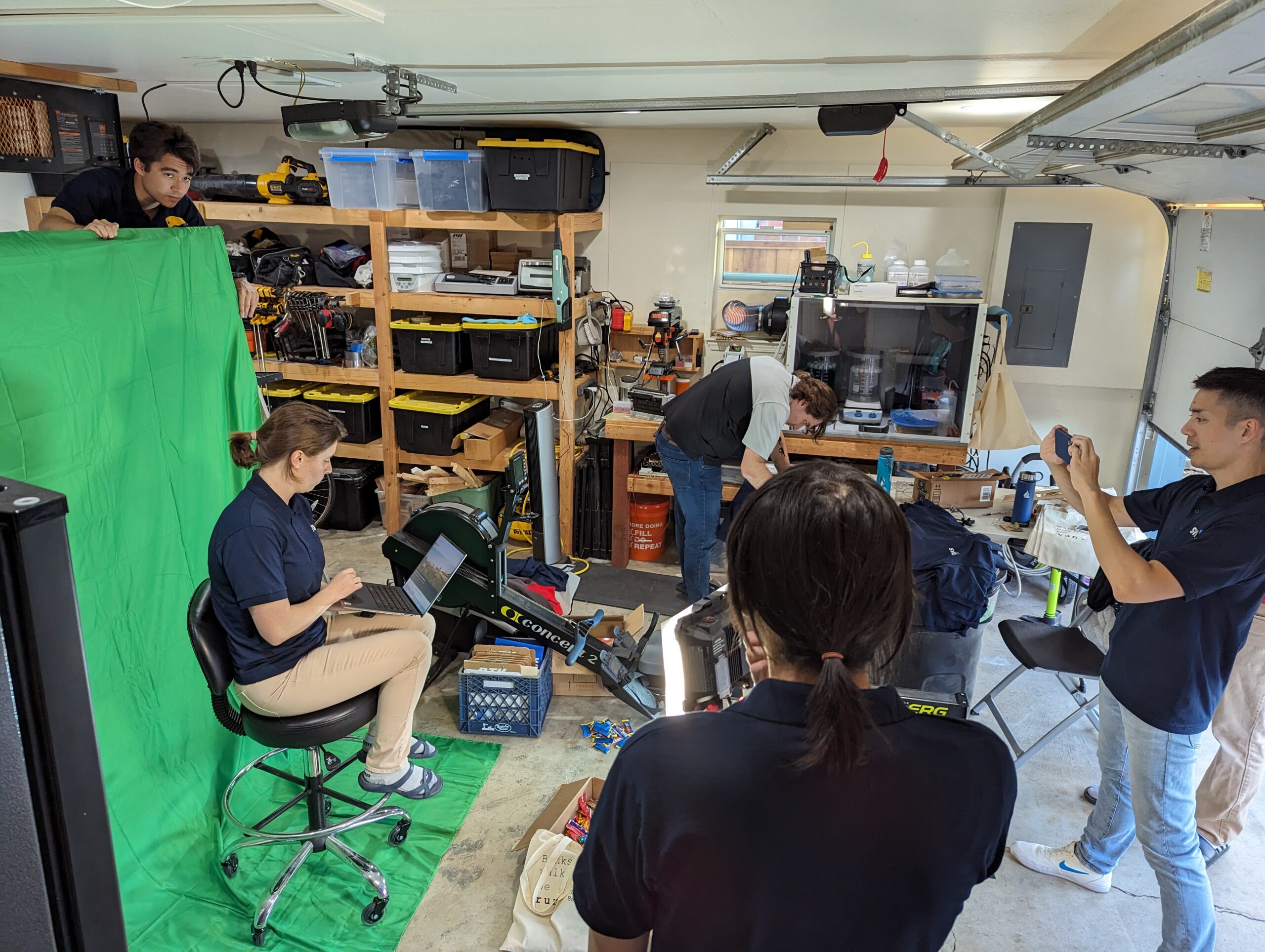
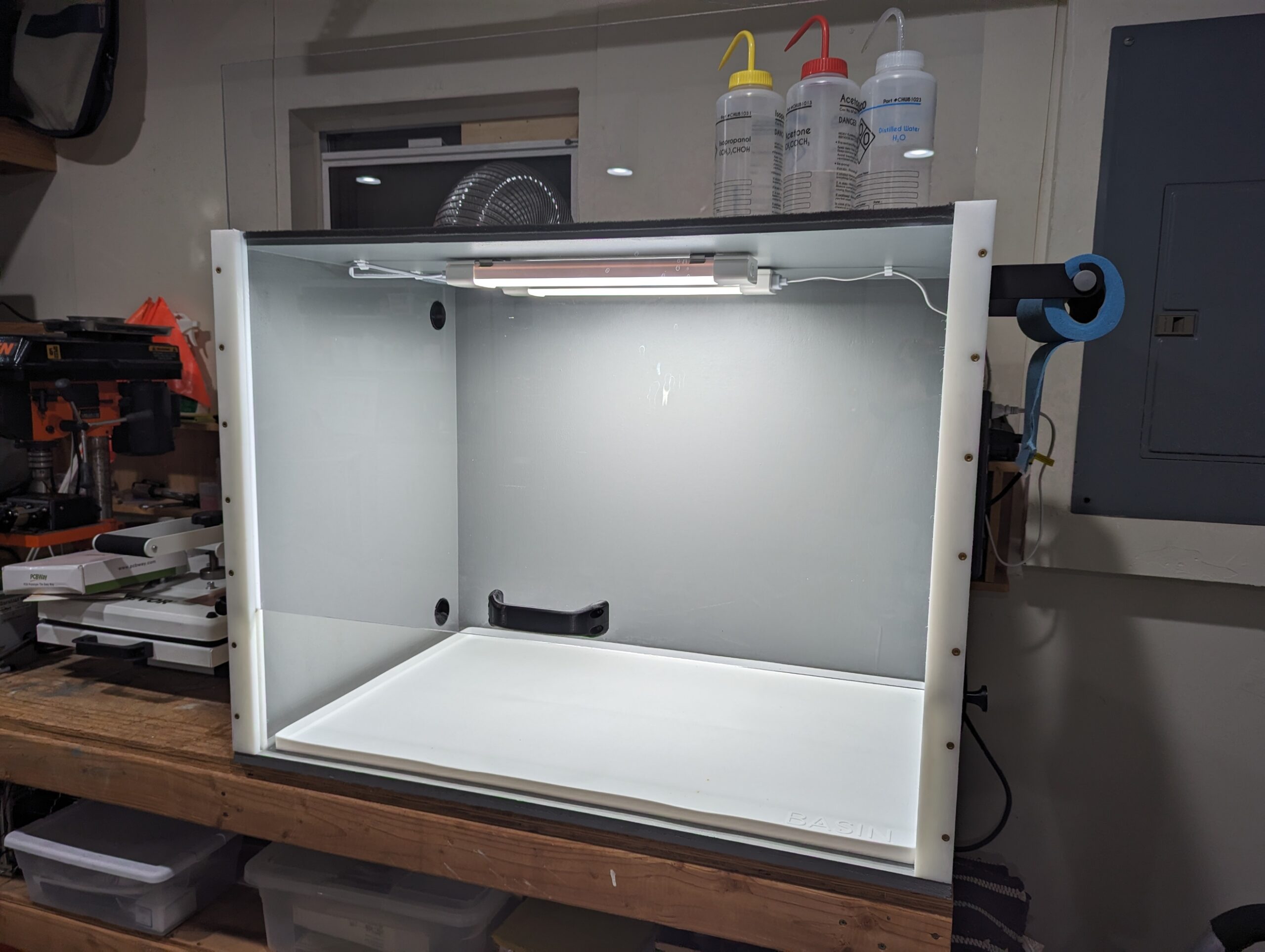
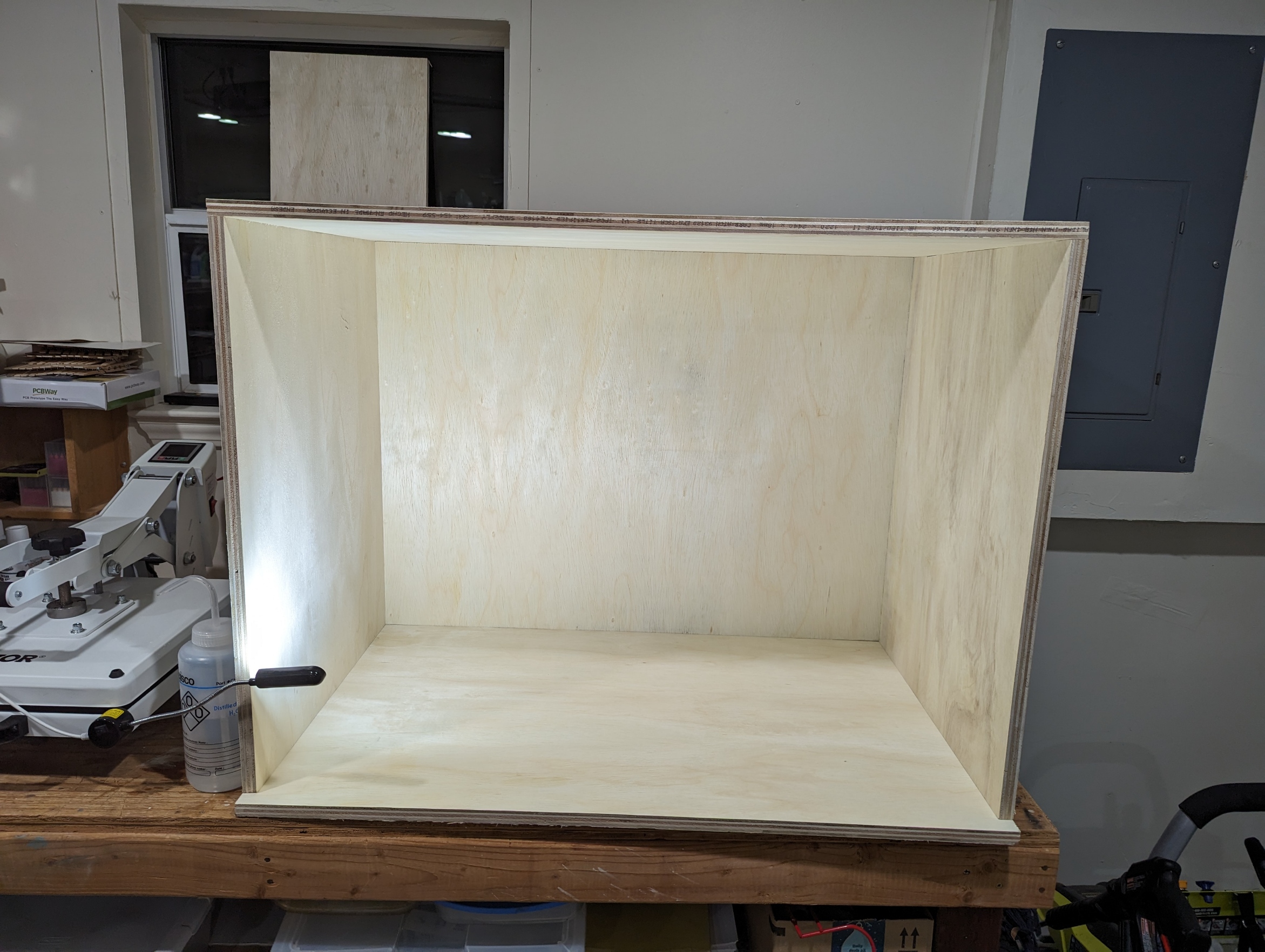
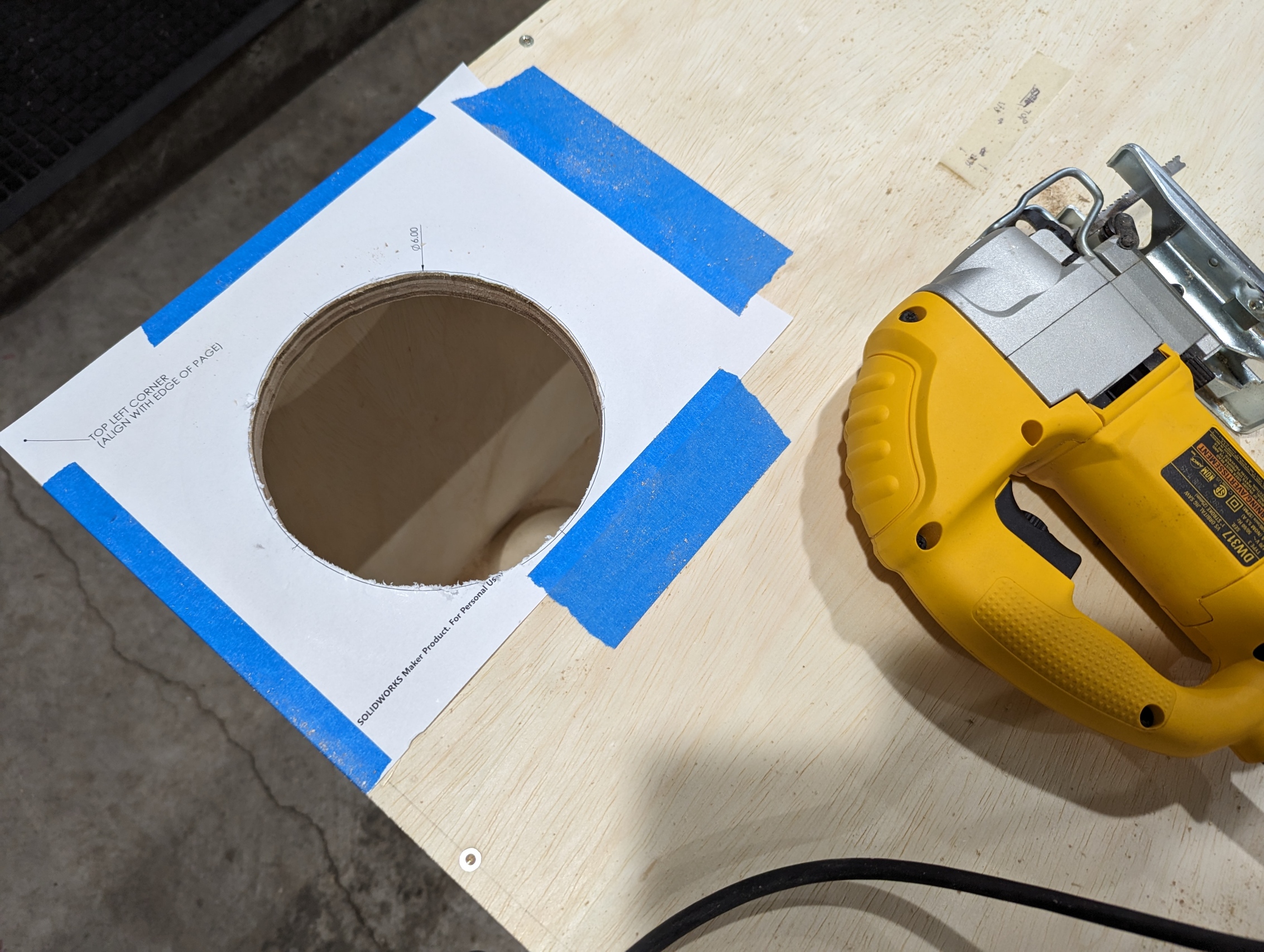
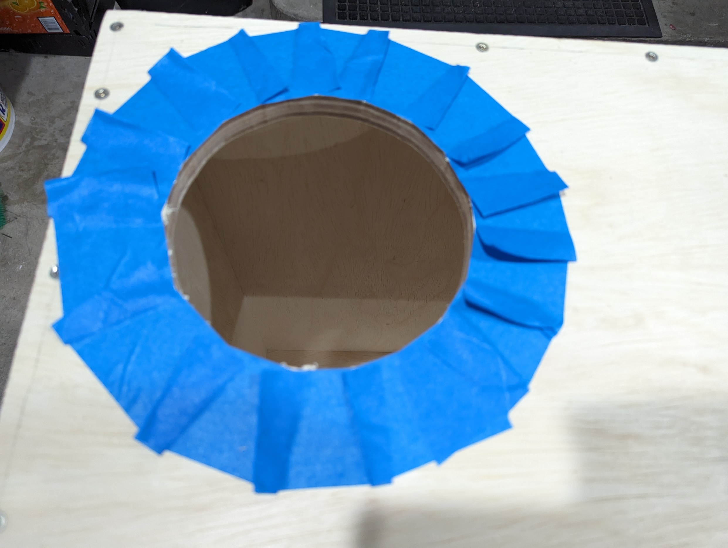
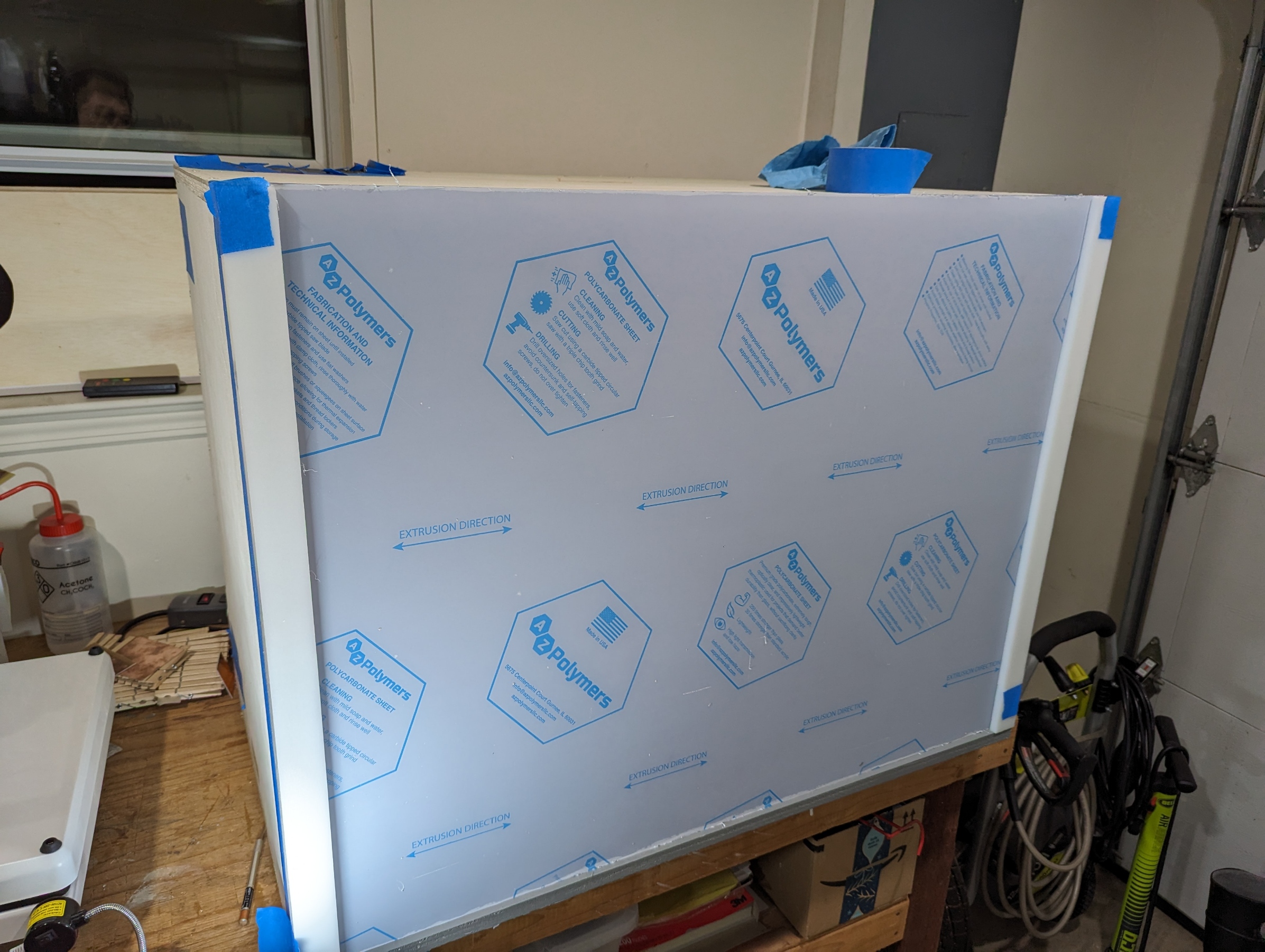
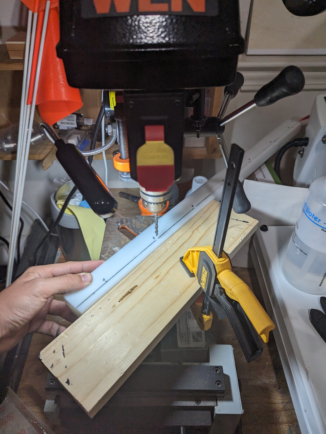
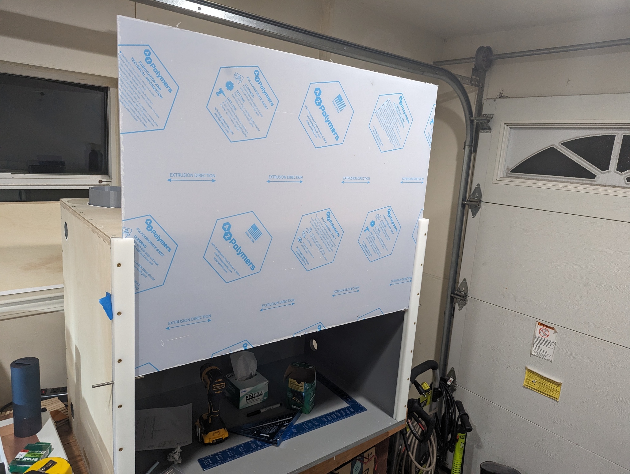
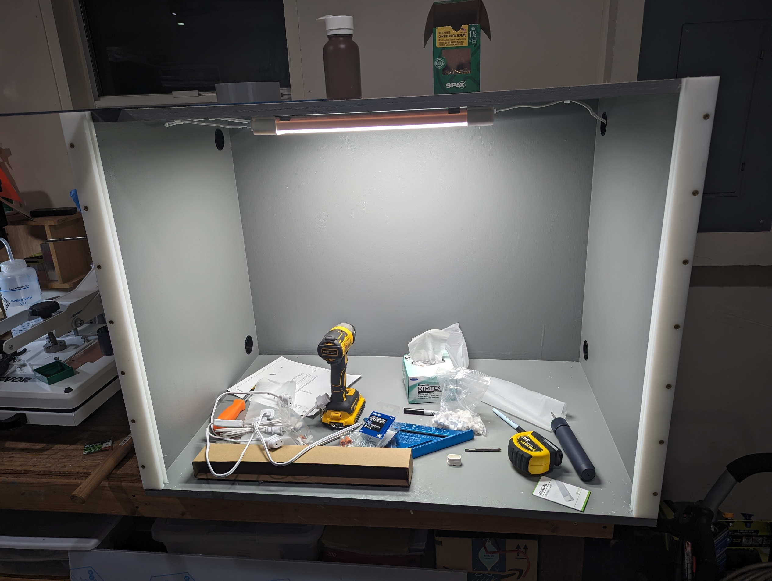
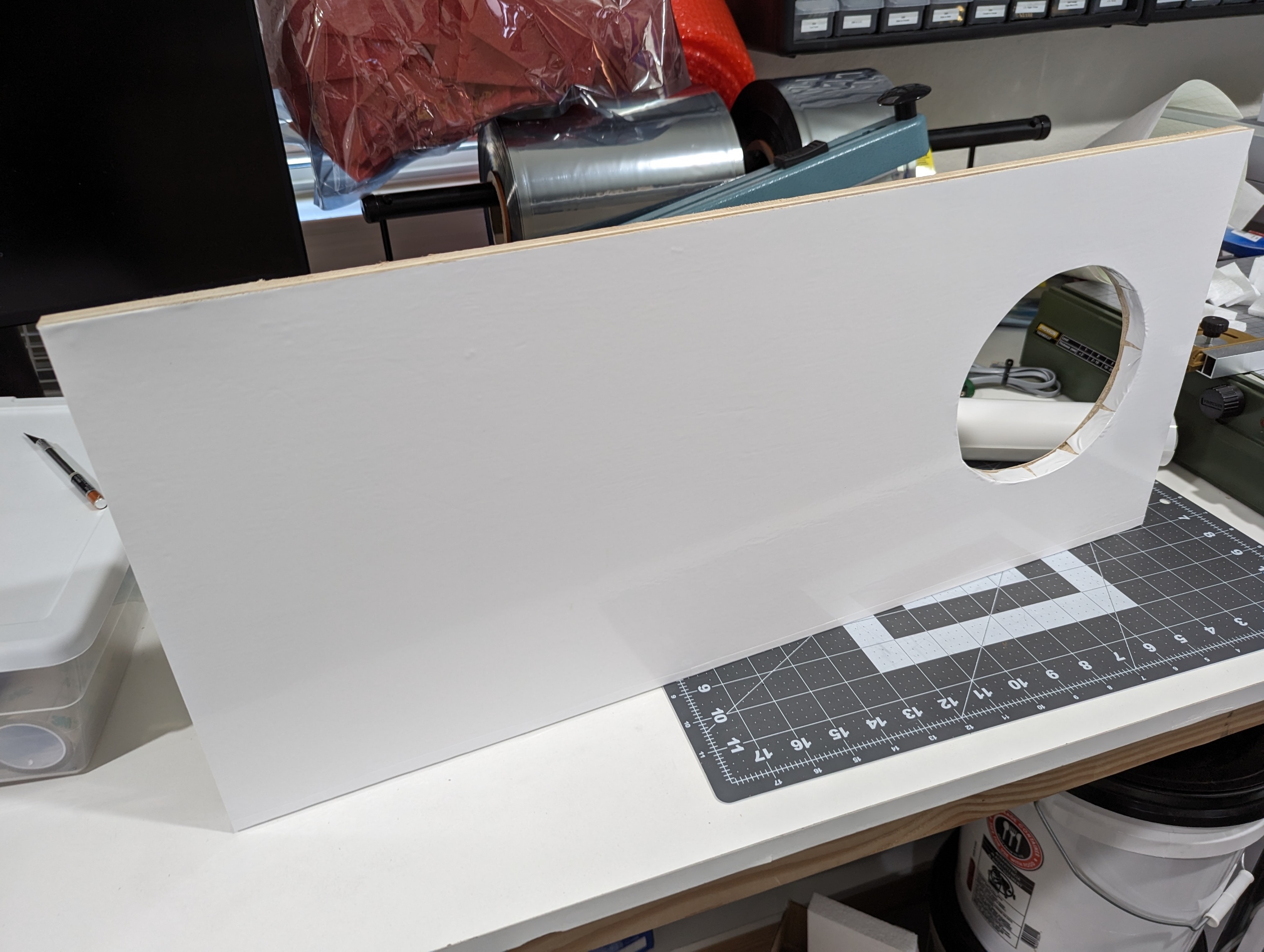
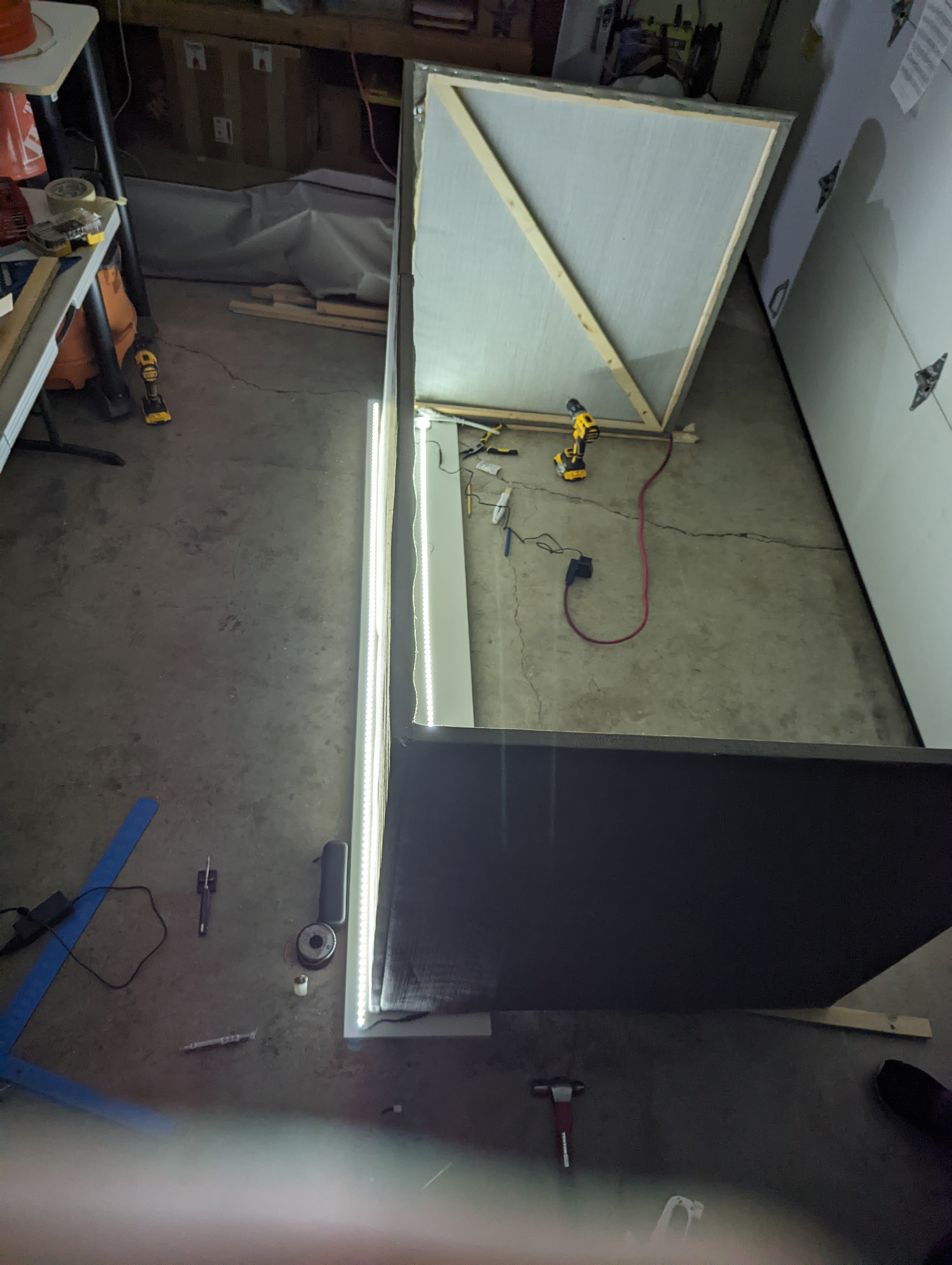
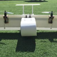
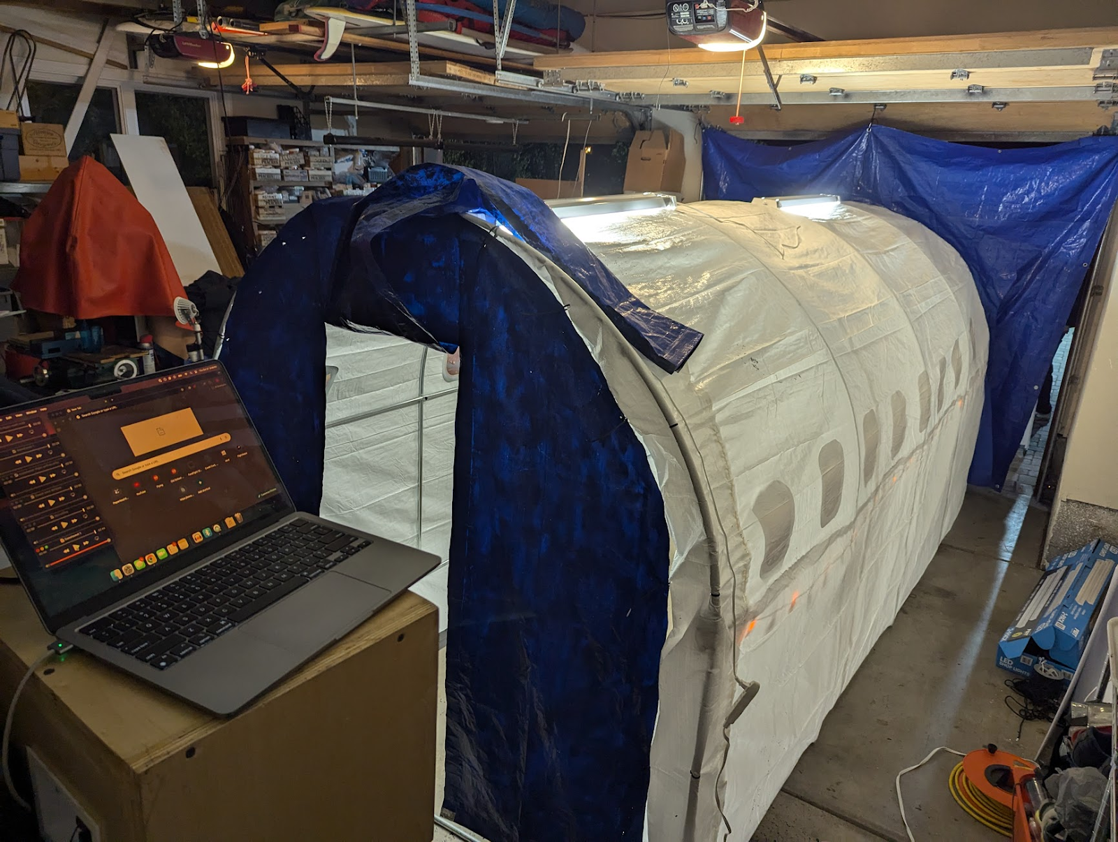
As luck would have it, a 15 foot greenhouse was inexpensive ($80) and just about the right size to fit these criteria, with the added bonus that the rounded top was strongly evocative of an airplane fuselage. During the weeks preceding Halloween, our team set about transforming the greenhouse into an airplane. The clear exterior plastic sheeting was replaced with a large white tarp, and paper windows were printed and attached to the inside of the fuselage with spray adhesive. A significant quantity of surprisingly affordable plastic folding chairs was installed and taped to the garage floor inside the fuselage to serve as seating.
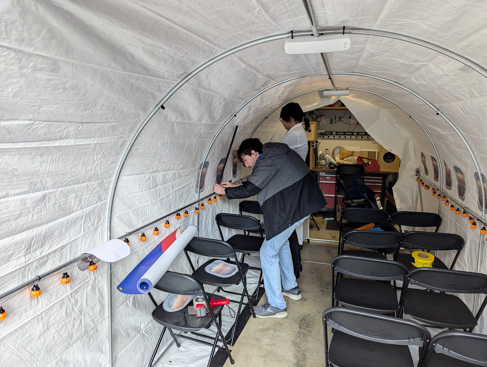
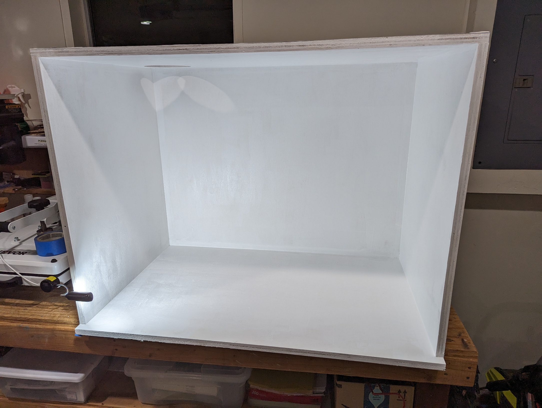
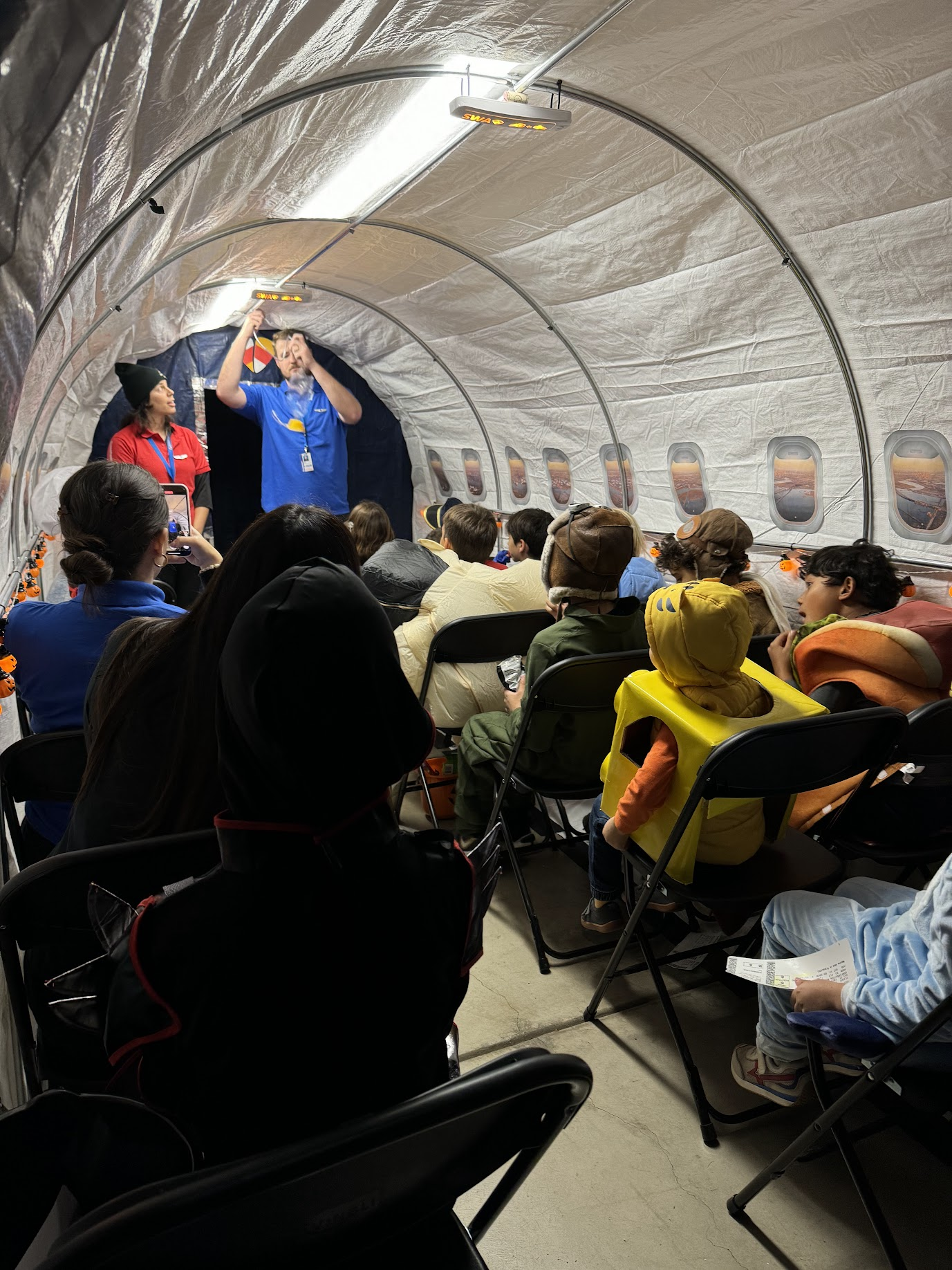
As a stand-in for floor-level exit lighting on typical passenger aircraft, jack-o-lantern string lights were installed along the side of the fuselage (and were referred to during the safety briefing). Lighting for the inside of the fuselage was provided by two LED light fixtures that were adhered to the top of the arch, on the outside of the white tarp serving as the fuselage skin. The lights diffused remarkably well through the tarp, and really helped sell the aircraft interior with their rectangular silhouettes and daylight color temperature.
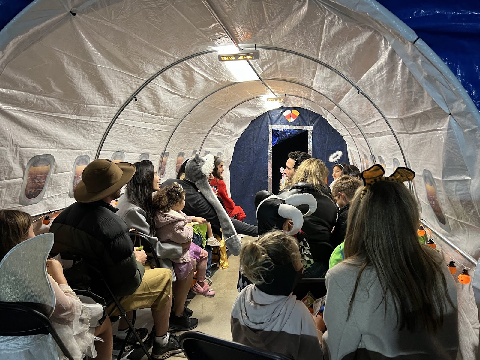
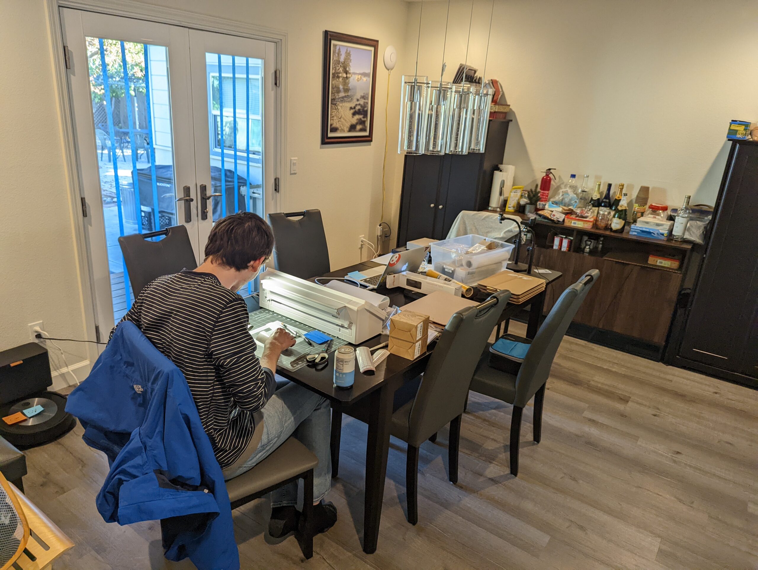
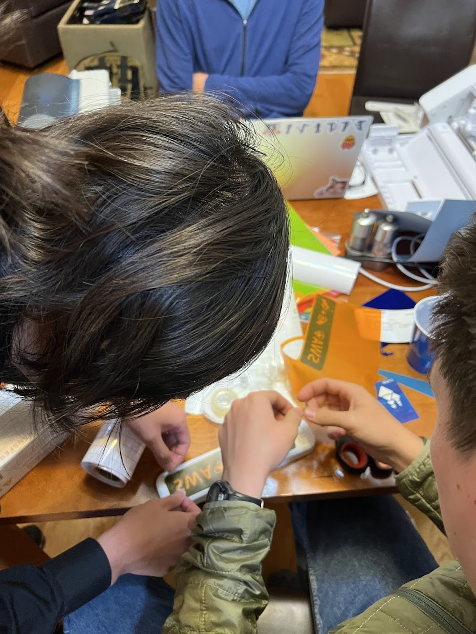
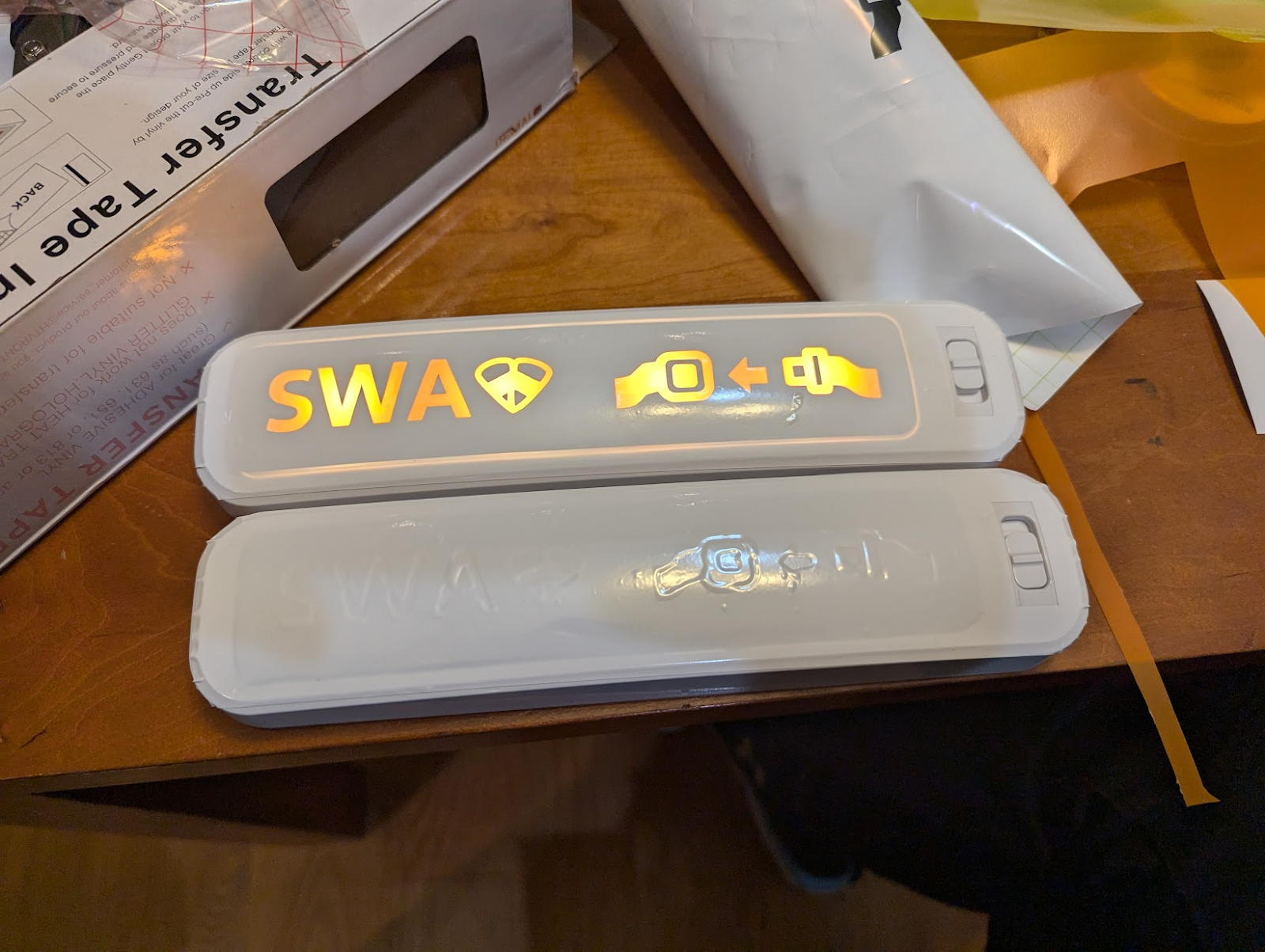
The night before halloween, one of our volunteers chanced upon a set of remote-controlled light bars in Target, and these were promptly transformed into remote-activated seatbelt signs for the interior of the aircraft with the help of the vinyl cutter (apparently, the trick to getting a good “seatbelt sign” effect is to use an orange binder divider as a colored diffuser, followed by black vinyl as a mask layer, followed by white vinyl as a top cover).
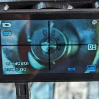
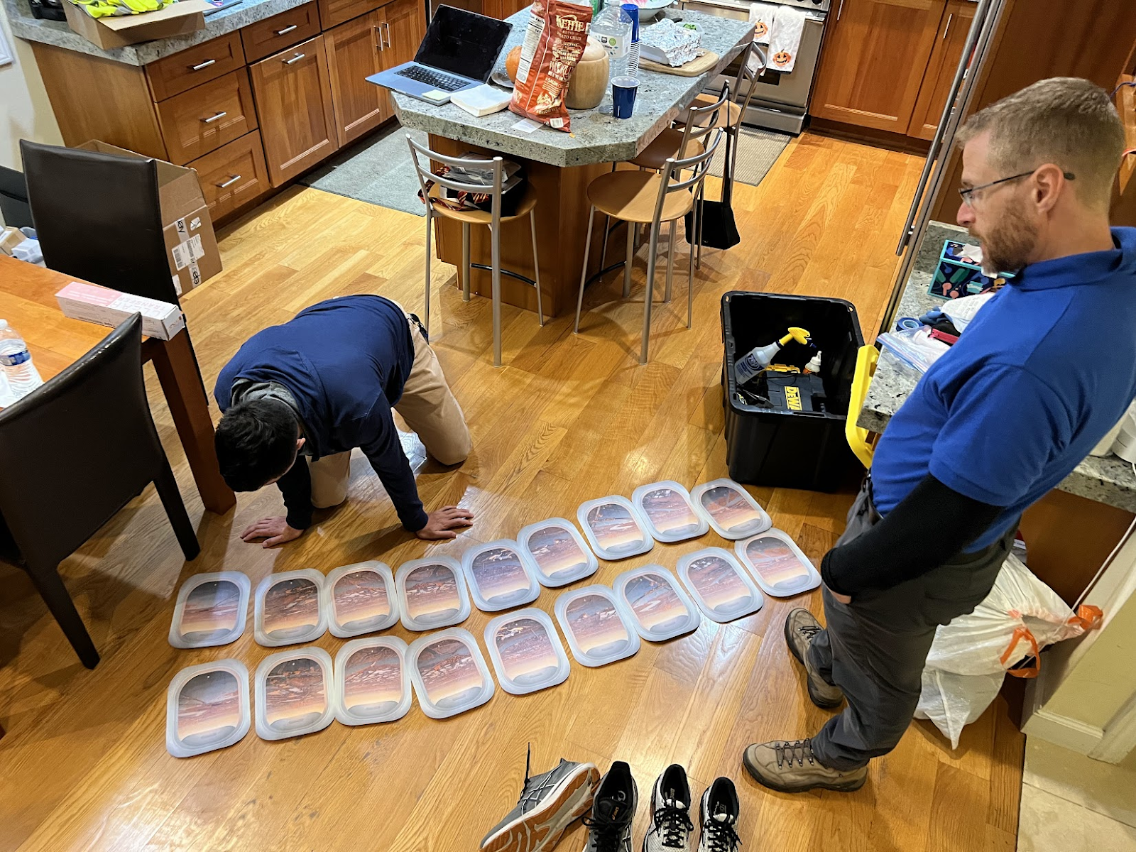
An aside about the windows: the scenery for the windows was pulled from a cell phone video taken out the window of an aircraft as it was landing. Subsequent frames of the video were used to create a unique perspective for each window, and then composited with a hand-drawn “window frame” in Affinity Designer to create a printable window for each row of the aircraft. The full row of windows was mirrored to create a different view for the other side of the aircraft. As a result, every window on the aircraft was actually a unique picture! This did lead to some confusion when I made the brilliant decision to not number the window printouts, and the entire pile of them was predictably dropped on the floor. Our volunteers spent at least fifteen minutes playing “spot the difference” with 18 unique picture cutouts to put them back in the right order.
To really sell the airplane experience, one of our volunteers crafted a series of audio files that included the pre-flight safety announcements as well as engine noise (takeoff / cruise / landing / reverse thrust) that were played over a speaker system in the garage.
During takeoff and landing, volunteers would slightly shake the outside of the fuselage to simulate vibrations. In addition to welcoming passengers onto the aircraft and telling them when the flight was over, our “pilot” (coincidentally, a real airline pilot), controlled the aircraft audio playback and seatbelt signs from the “cockpit”, a laptop in the garage.
Each flight had two volunteers working as flight attendants. The flight attendants performed a cabin check and safety briefing (with props) before takeoff, ran a snack service during cruise, and hid in the cockpit area (outside of passenger view) during takeoff and landing.
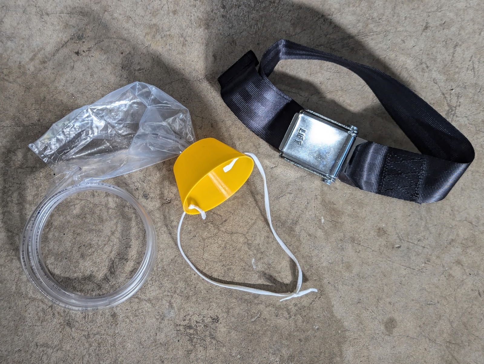
For the safety demonstration, we used a standard seatbelt extender to demonstrate safe buckling and unbuckling of seatbelts, and used an oxygen mask prop that we cobbled together from a 3D printed cup, some ear straps from a COVID-era N95, tubing from Home Depot, and a Ziploc bag.
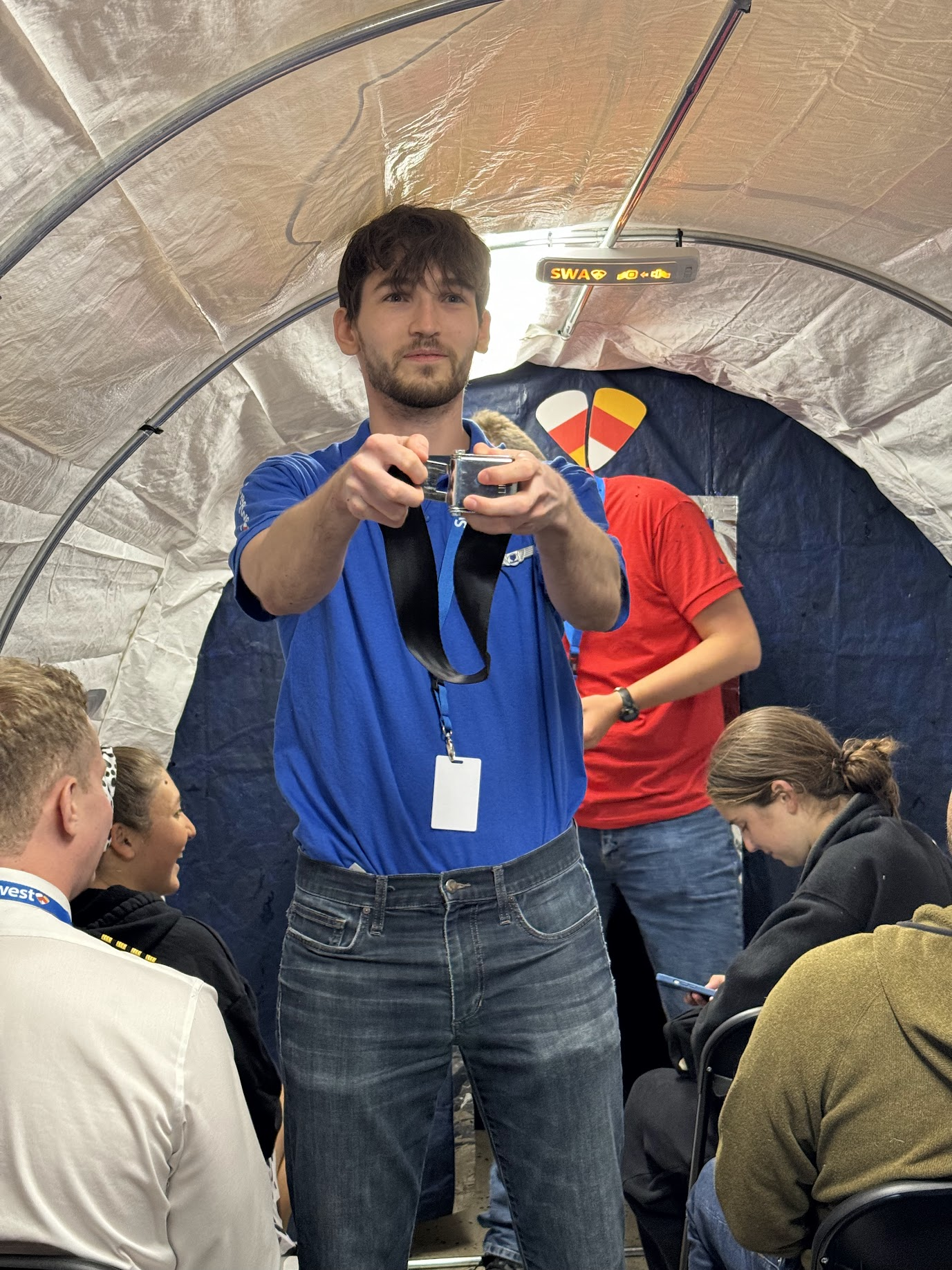
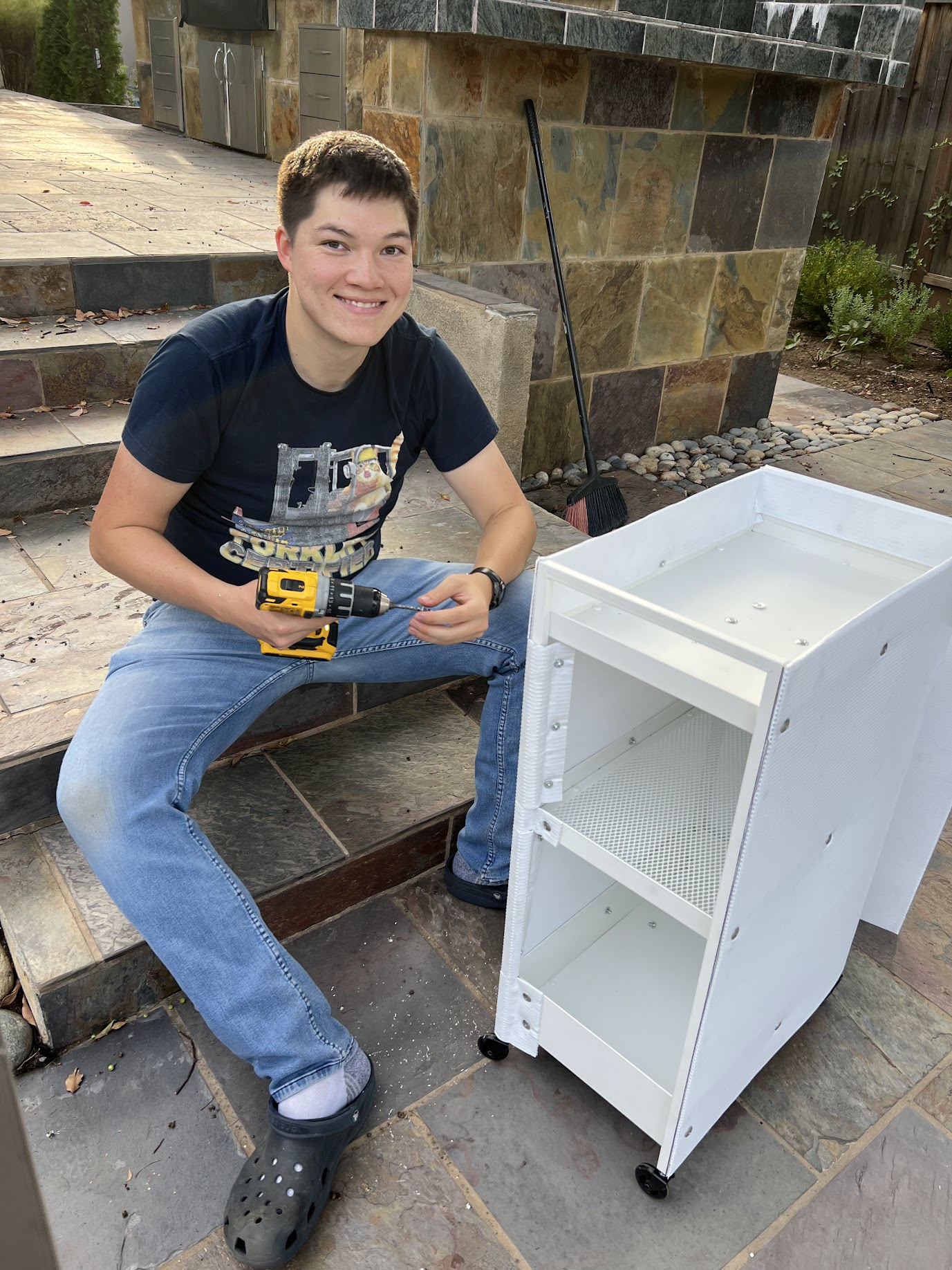
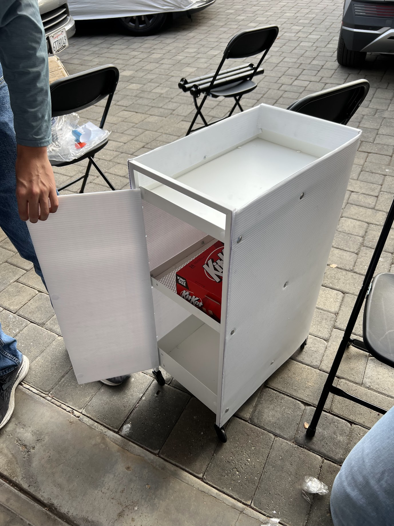
The snack cart utilized in the aircraft was a $30 cart from IKEA that we wrapped in a piece of white coroplast, fastened to the cart frame with aluminum pop rivets. Kids LOVED the snack cart–a highlight of Halloween night was hearing an audible reaction from the aircraft every time the flight attendants emerged from the forward bulkhead for candy service.
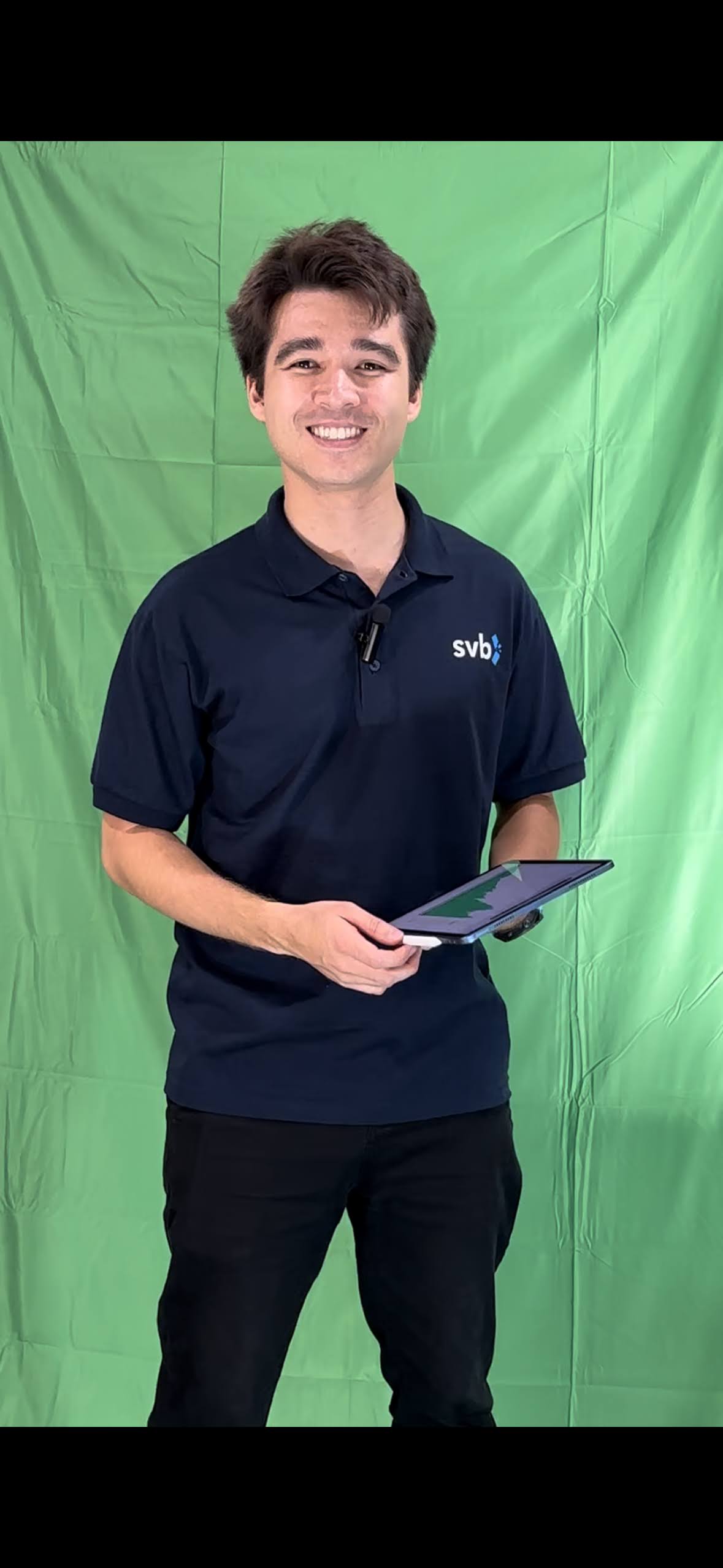
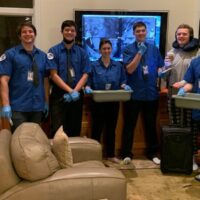
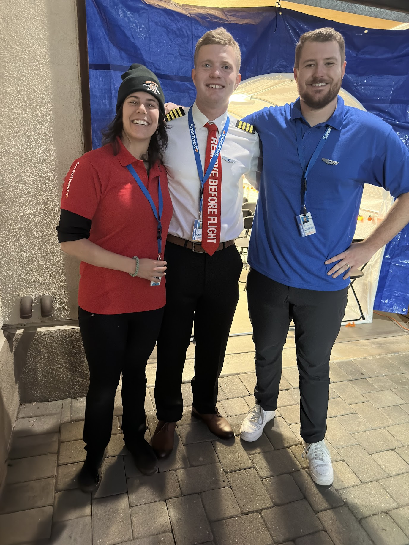
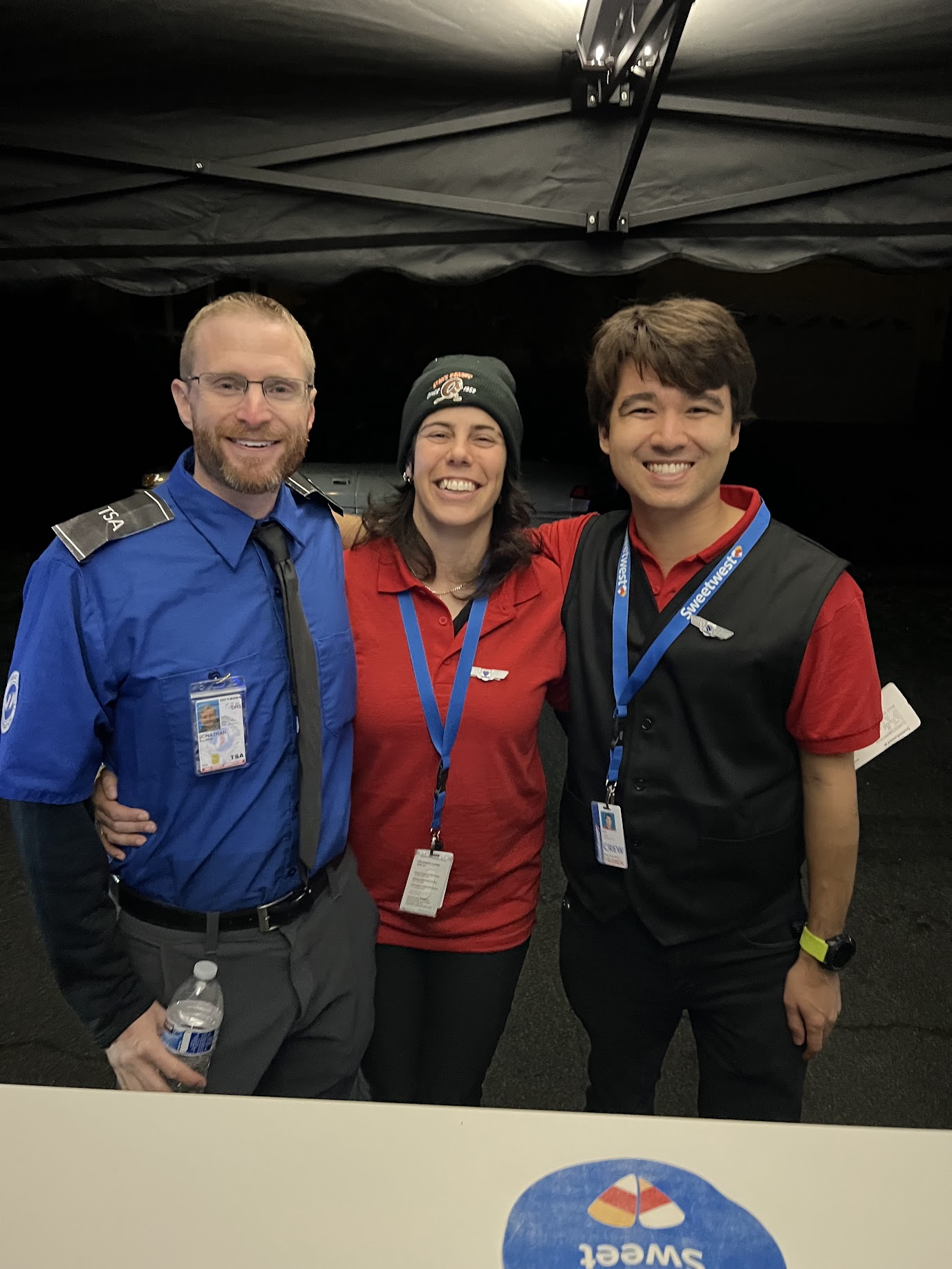
Costumes
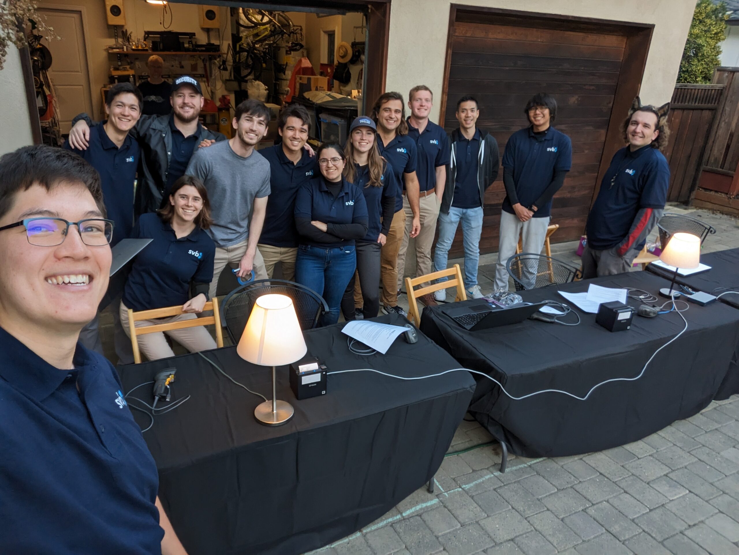
No good Halloween whatchamacallit would be good without costumes! We had a record number of unique costumes for our Sweetwest Airlines event.
- Pilot
- Ramp Agent
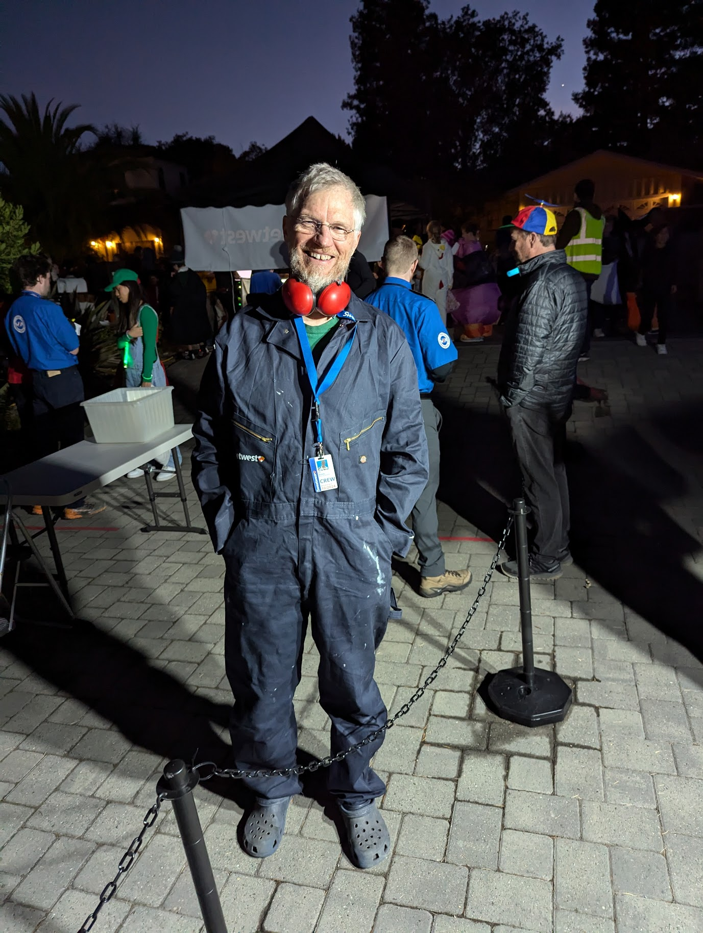
- Maintenance Crew
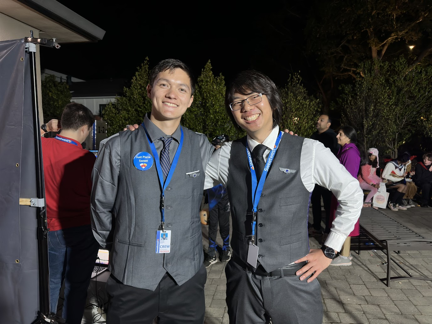
- Flight Attendant (fancy)
- Flight Attendant (casual)
- Gate Agent
- Ticket Agent
- TSA Officer
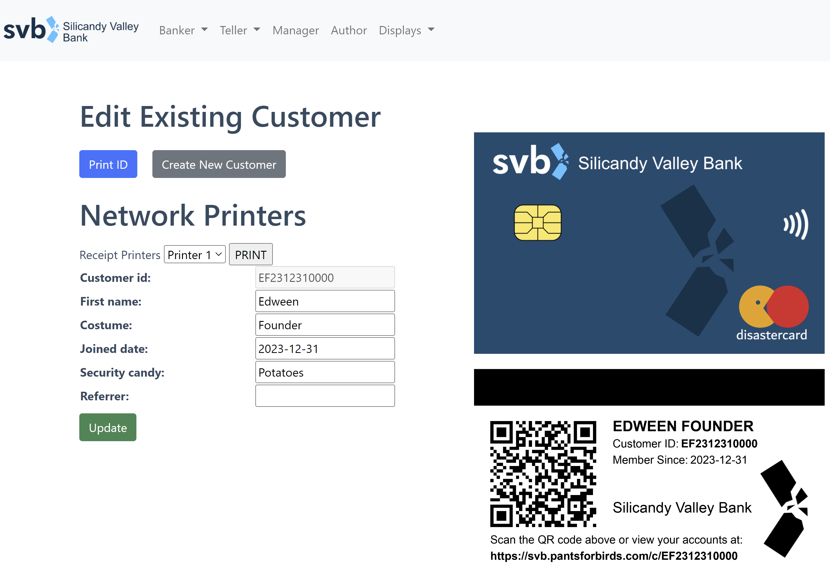
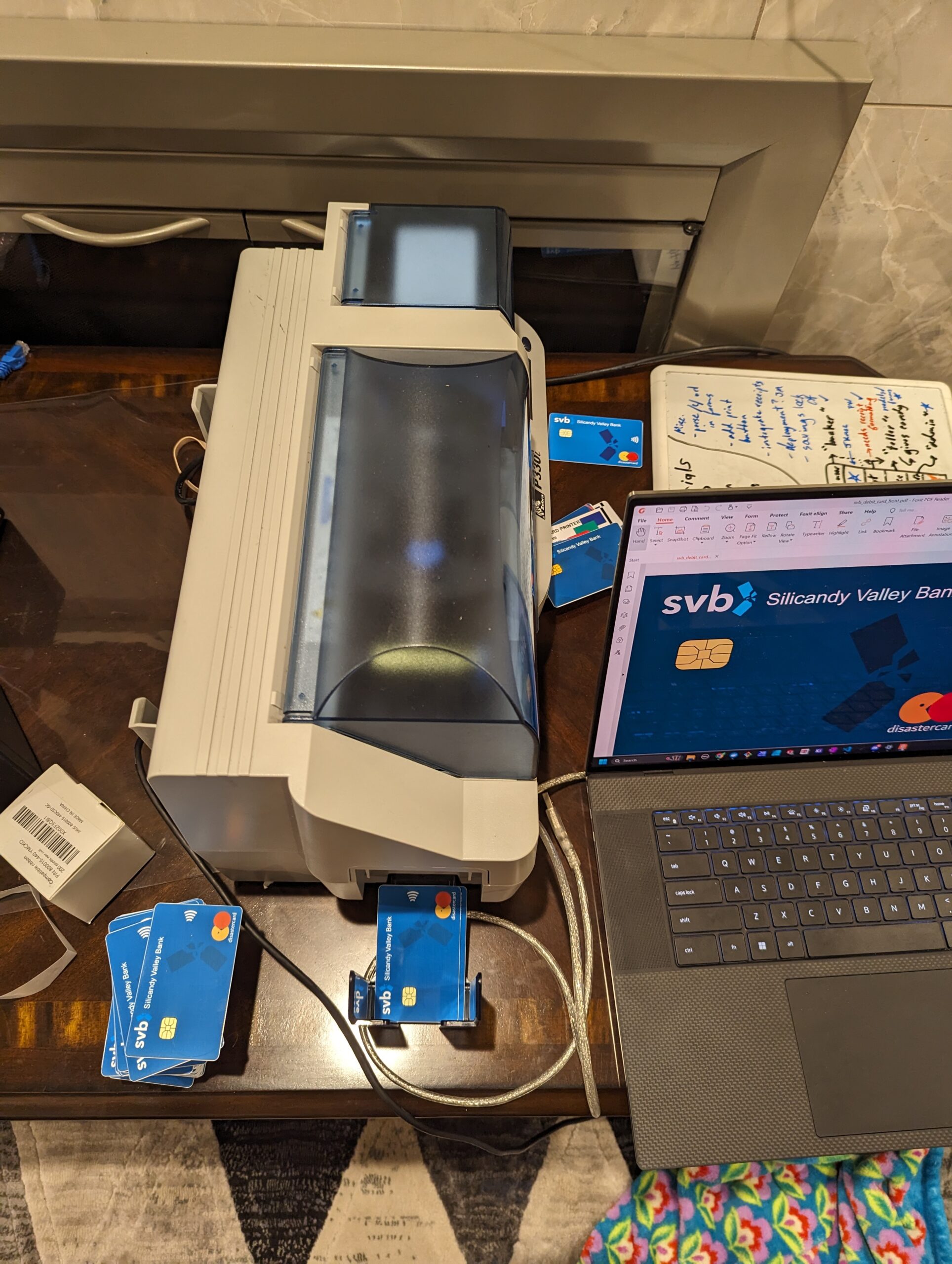
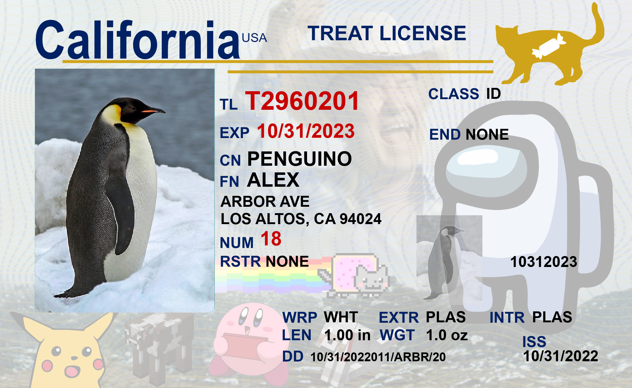
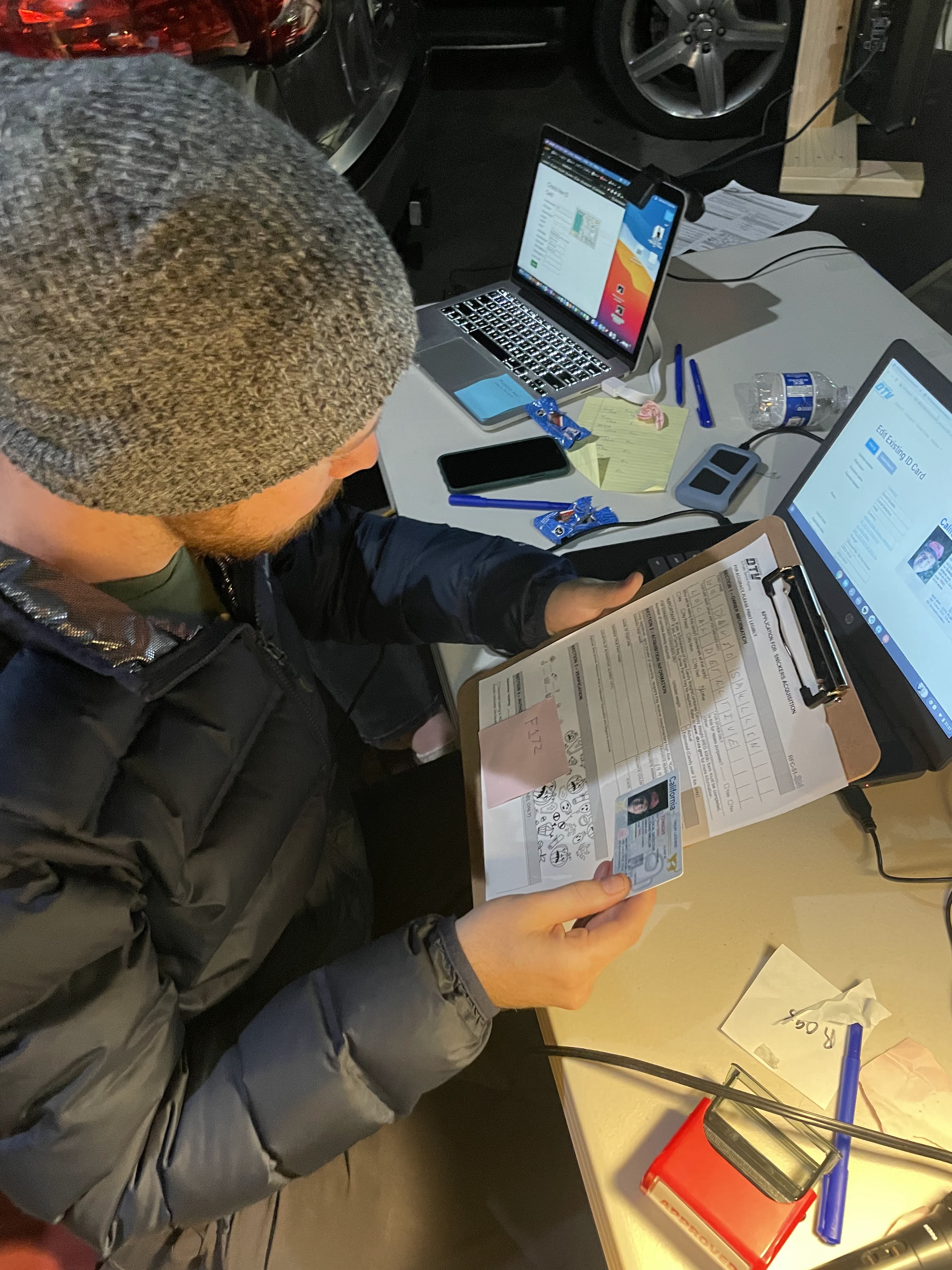
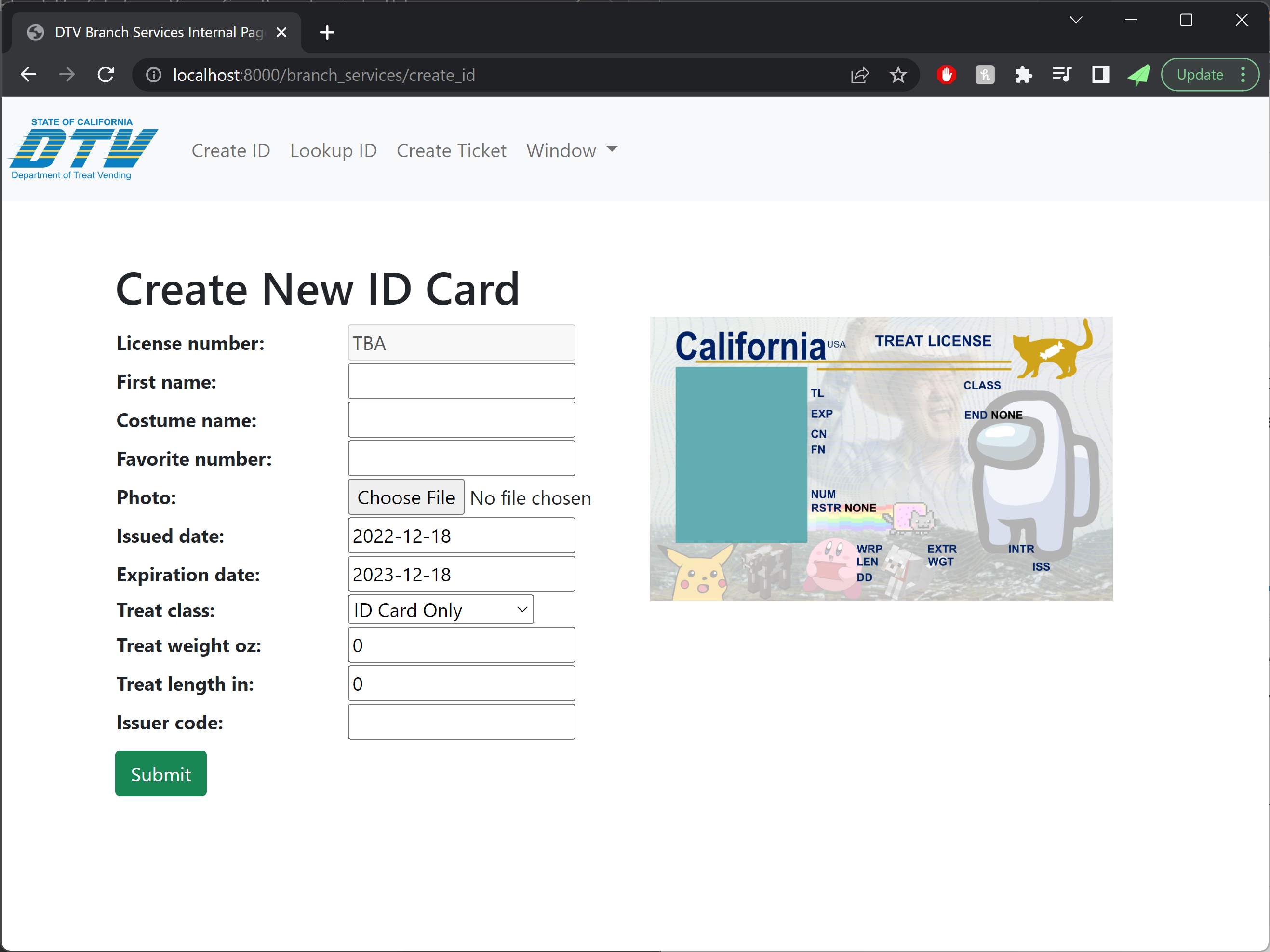
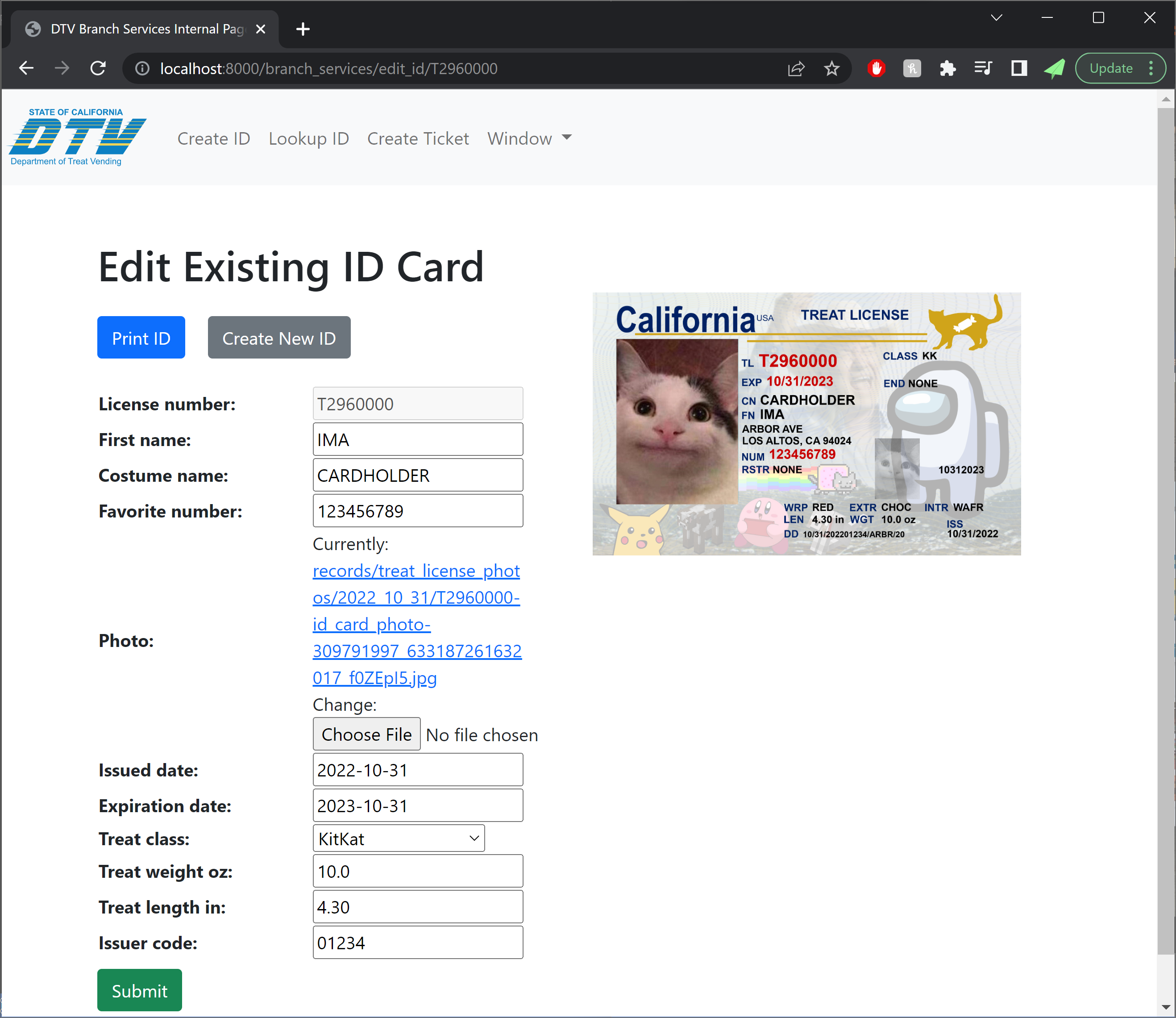
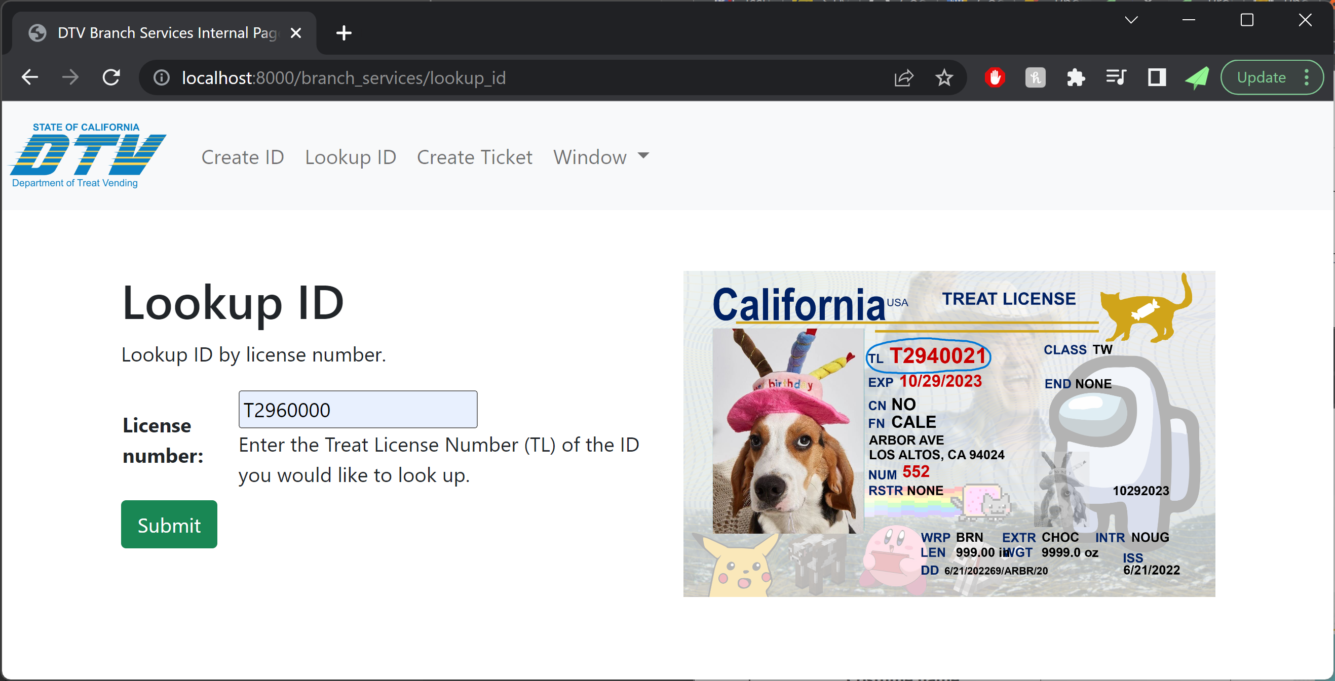
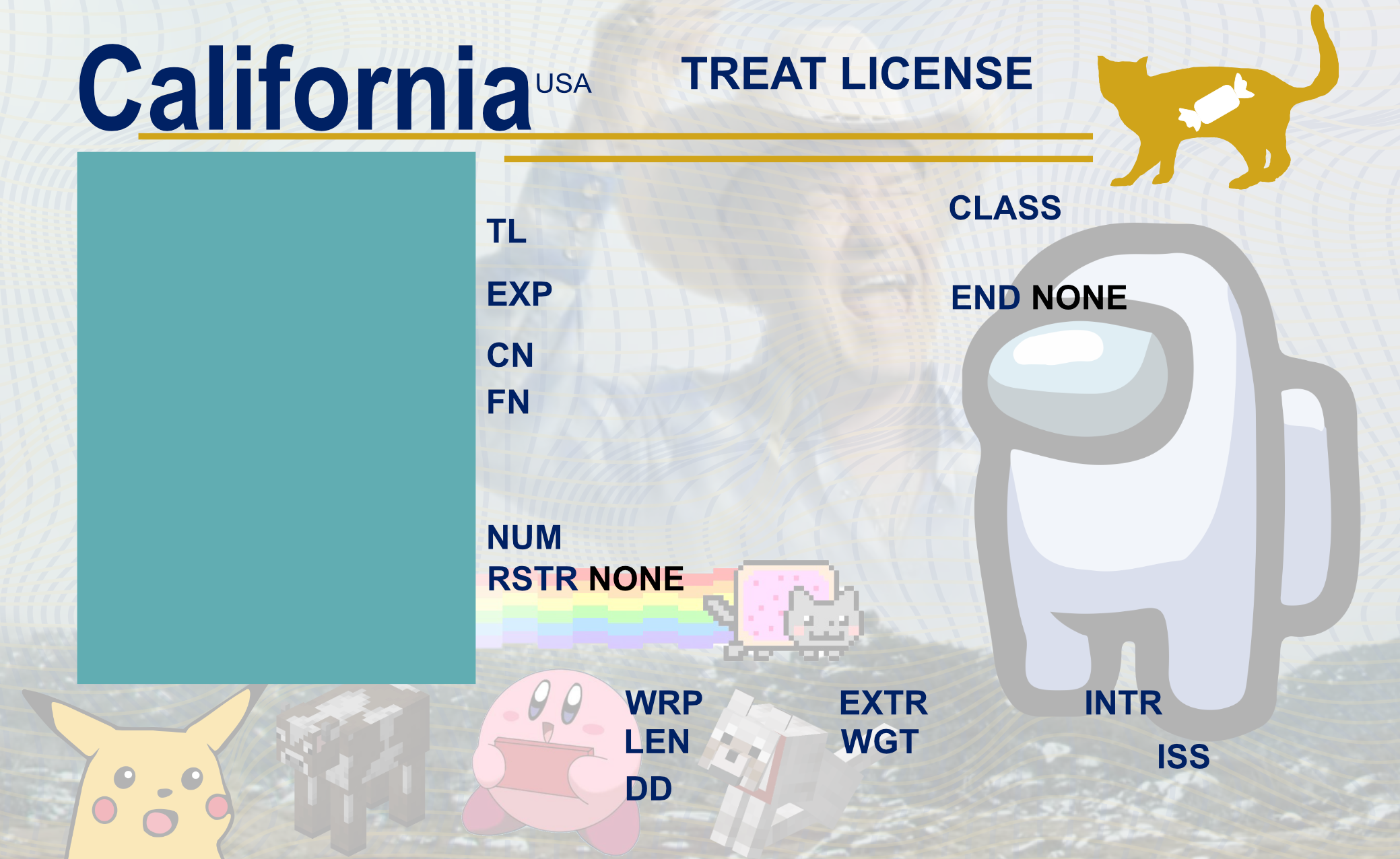
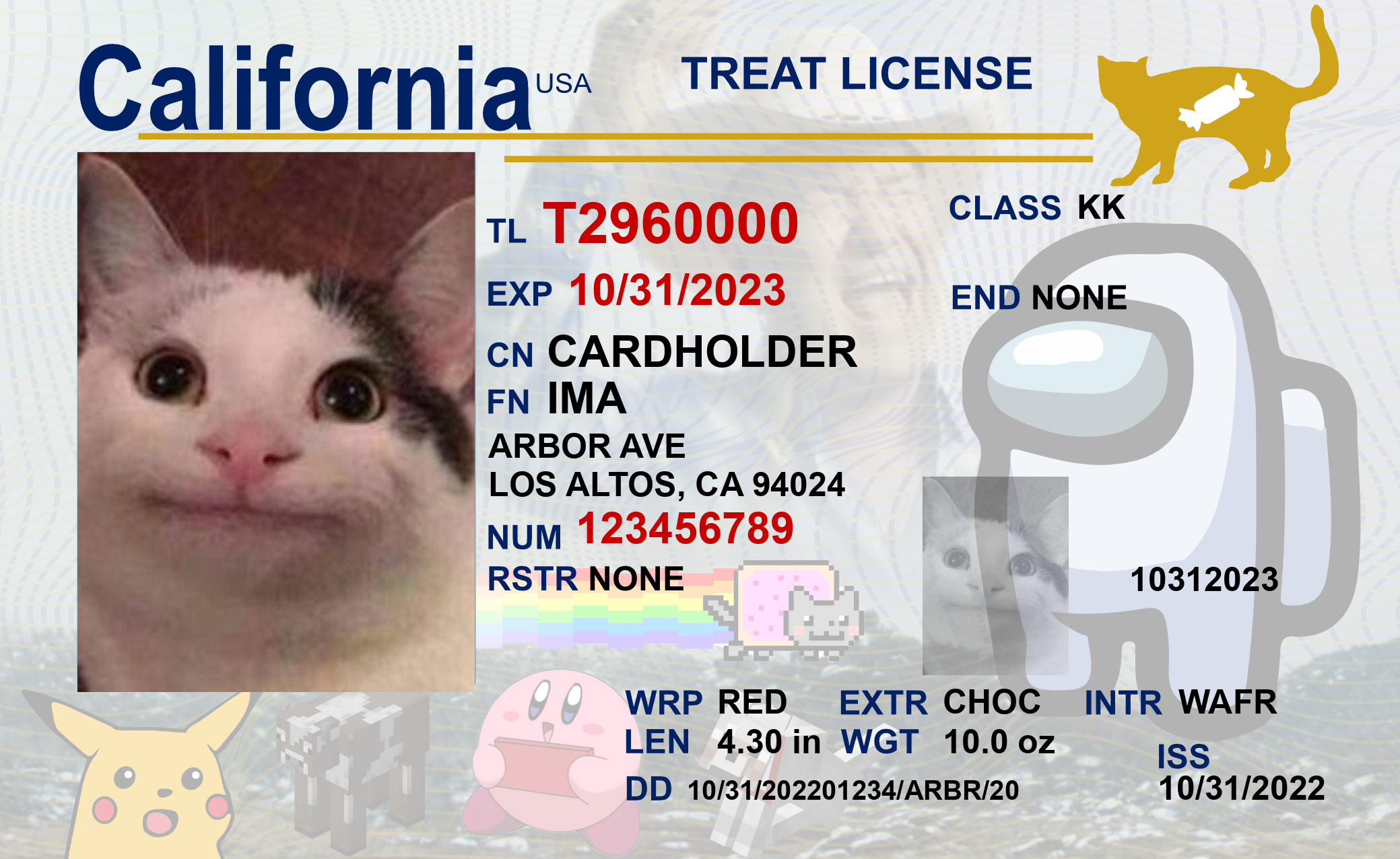
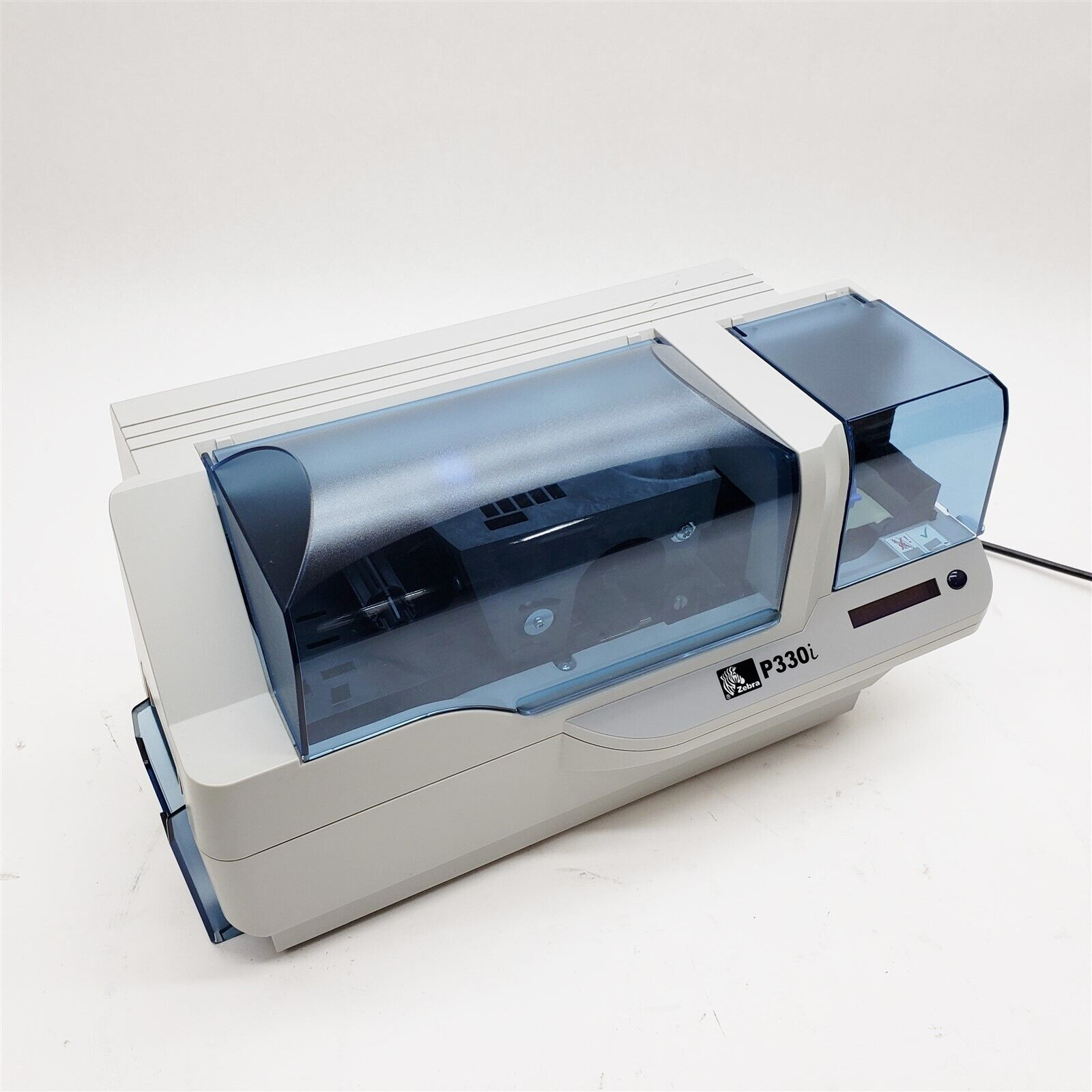
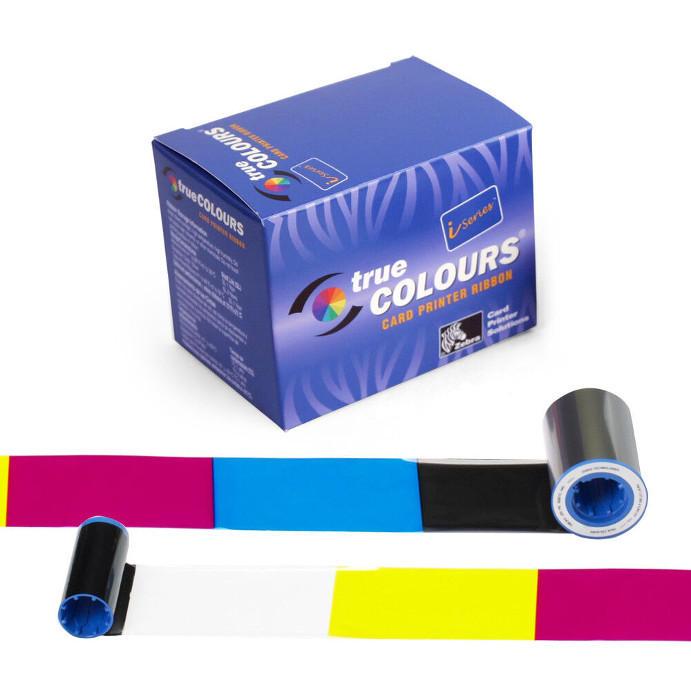
Each costume came with its own ID card, which we printed off using our ID card printer from previous years.
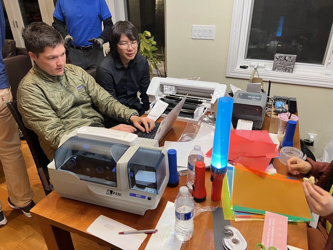
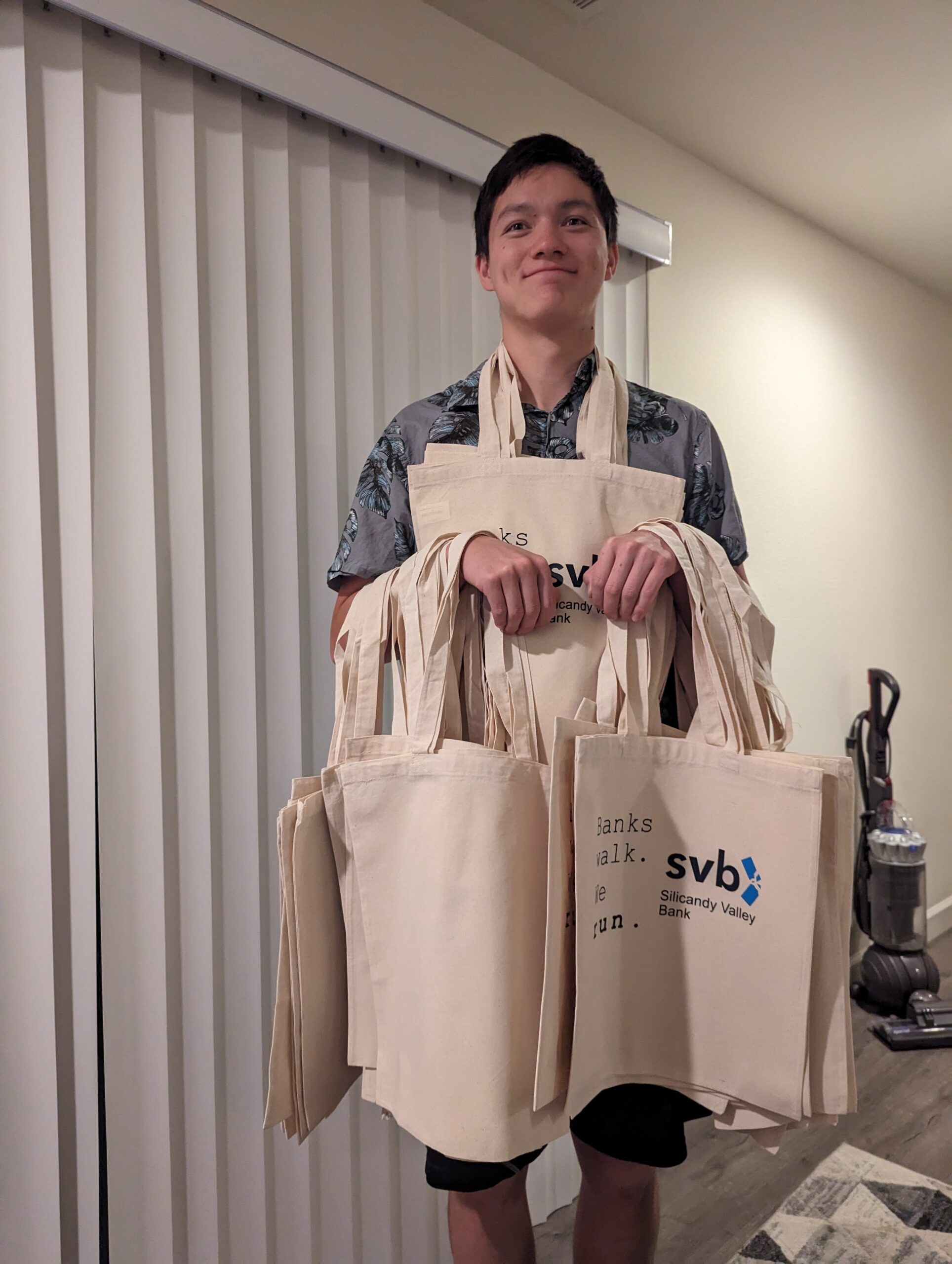
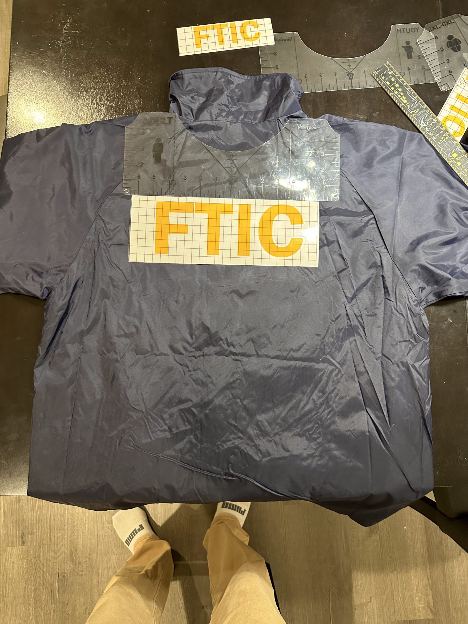
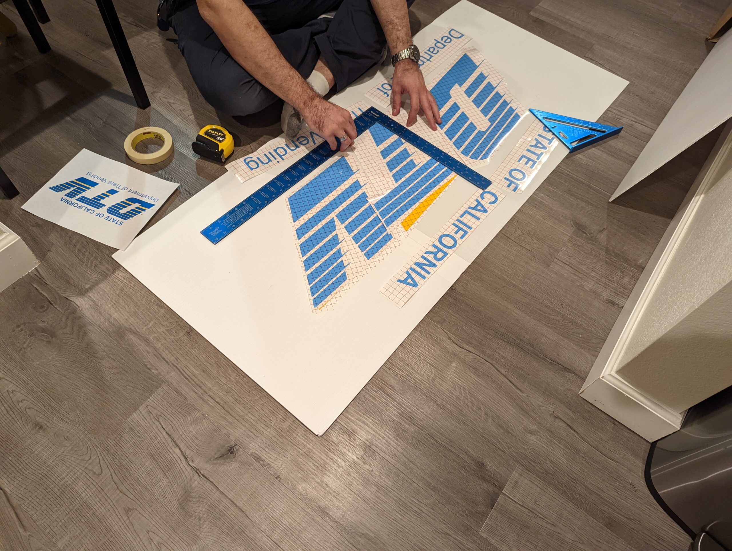
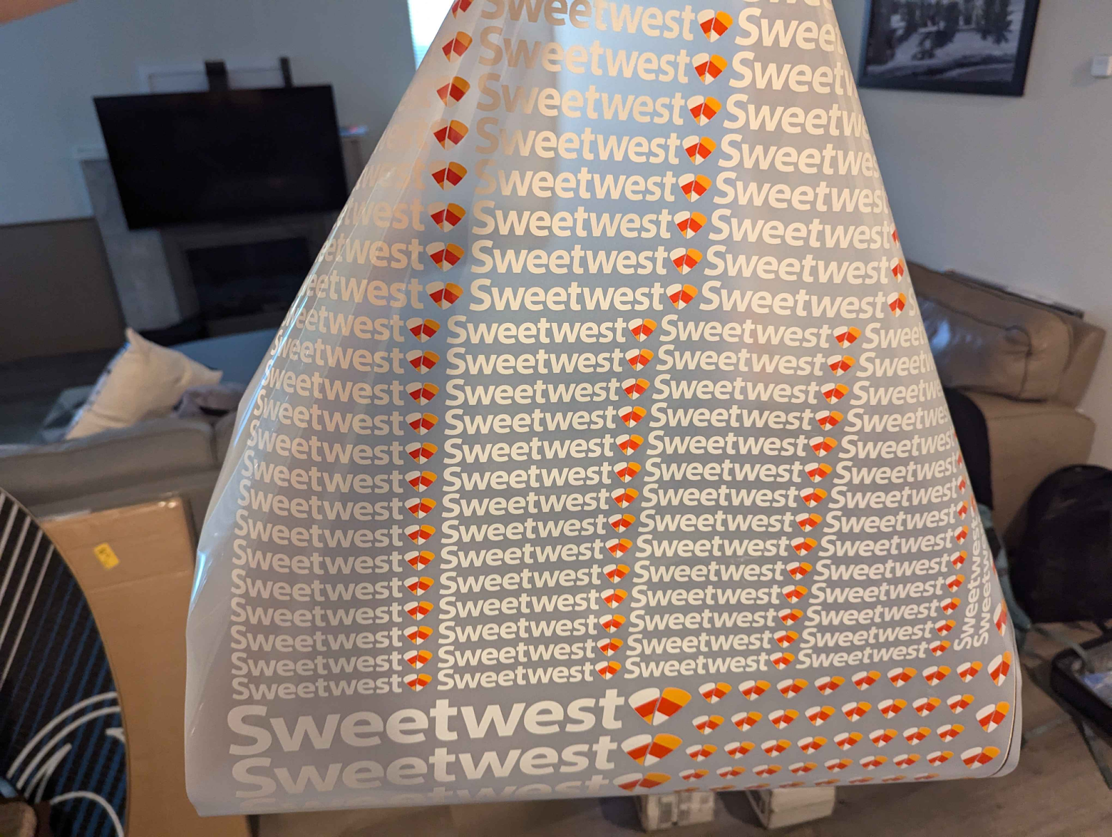
We handcrafted custom Sweetwest branded lanyards using some blue lanyard blanks off of Amazon and some direct transfer film prints of the Sweetwest Airlines logo, which were applied via a heat press. All branding on reflective vests, polo shirts, and maintenance coveralls were applied in the same fashion. The direct transfer film proved to be super affordable and a huge timesaver. We paid just $30 for a gang sheet of all the logos we needed for the entire costume, and didn’t spend more than a few hours cutting the logos out and applying them to blanks with the heat press! This saved probably 7-8 person-hours of labor that would have otherwise been spent weeding vinyl cutouts and compositing different vinyl parts together to form multi-colored logos.
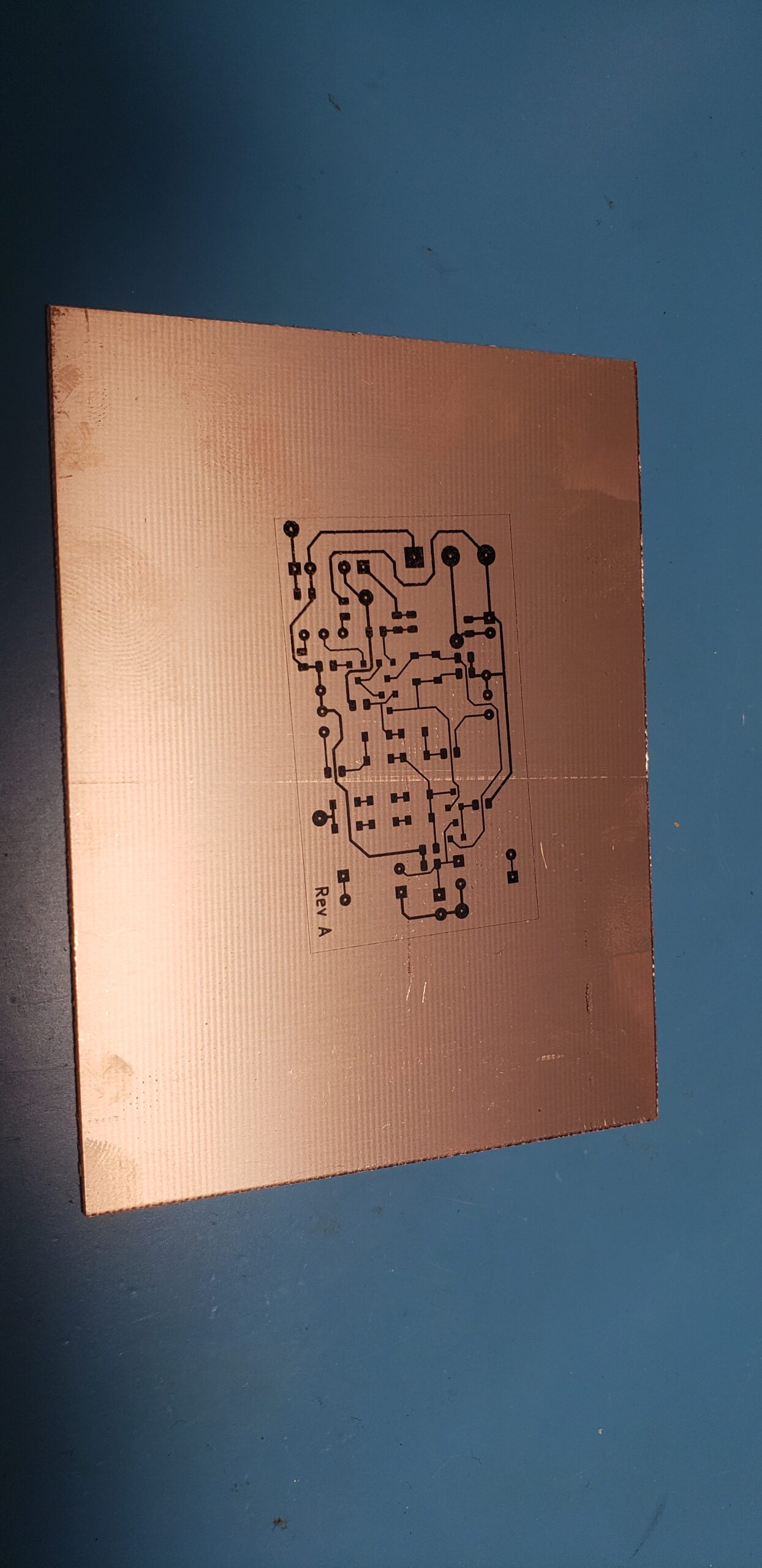
IT Systems
IT Systems: Background
The main goal of any software we add to our Halloween costumes is to make the experience come alive, both in terms of functionality and aesthetics.
From the initial brainstorming phase of this year’s concept, it was clear that successful execution would require central tracking of tickets as a bare minimum. After encountering technical difficulties the previous Halloween, one of our main goals was ensuring that the infrastructure we created this year would be extremely robust and reliable. As the idea expanded, so did our technical aspirations, increasing the complexity of the overall project.
We initially defined two main flows to build:
- Trick-or-treaters should be able to get a printed boarding pass.
- Volunteer team members and trick-or-treaters should be able to see flight information (time and status).
A lot of the pieces that would make it into the final costume were not there yet — for example, we didn’t talk explicitly about scanning barcodes, and we certainly didn’t talk about using PDF417 (the format real boarding passes use) to actually use scanned boarding pass information to mark passengers as boarded.
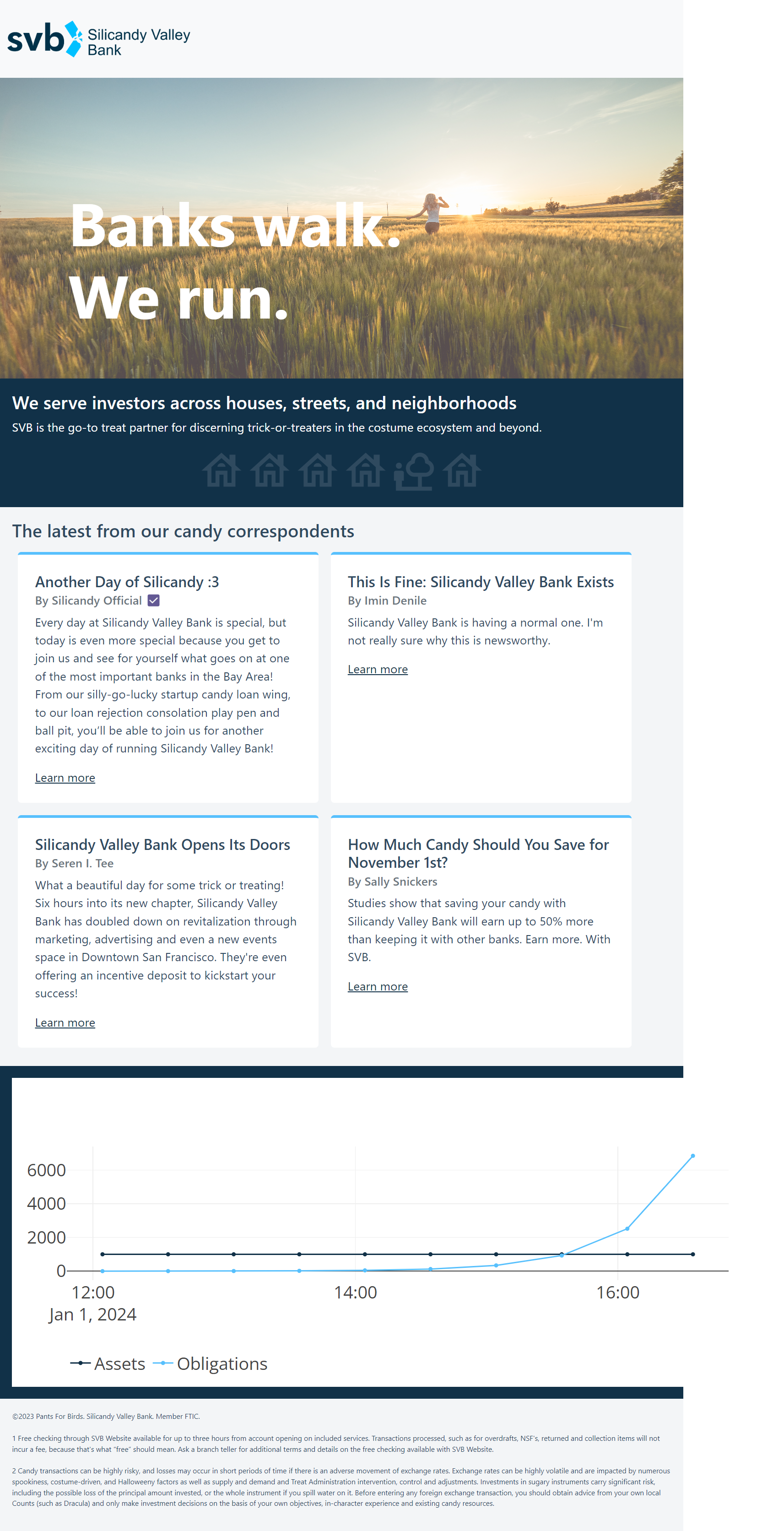
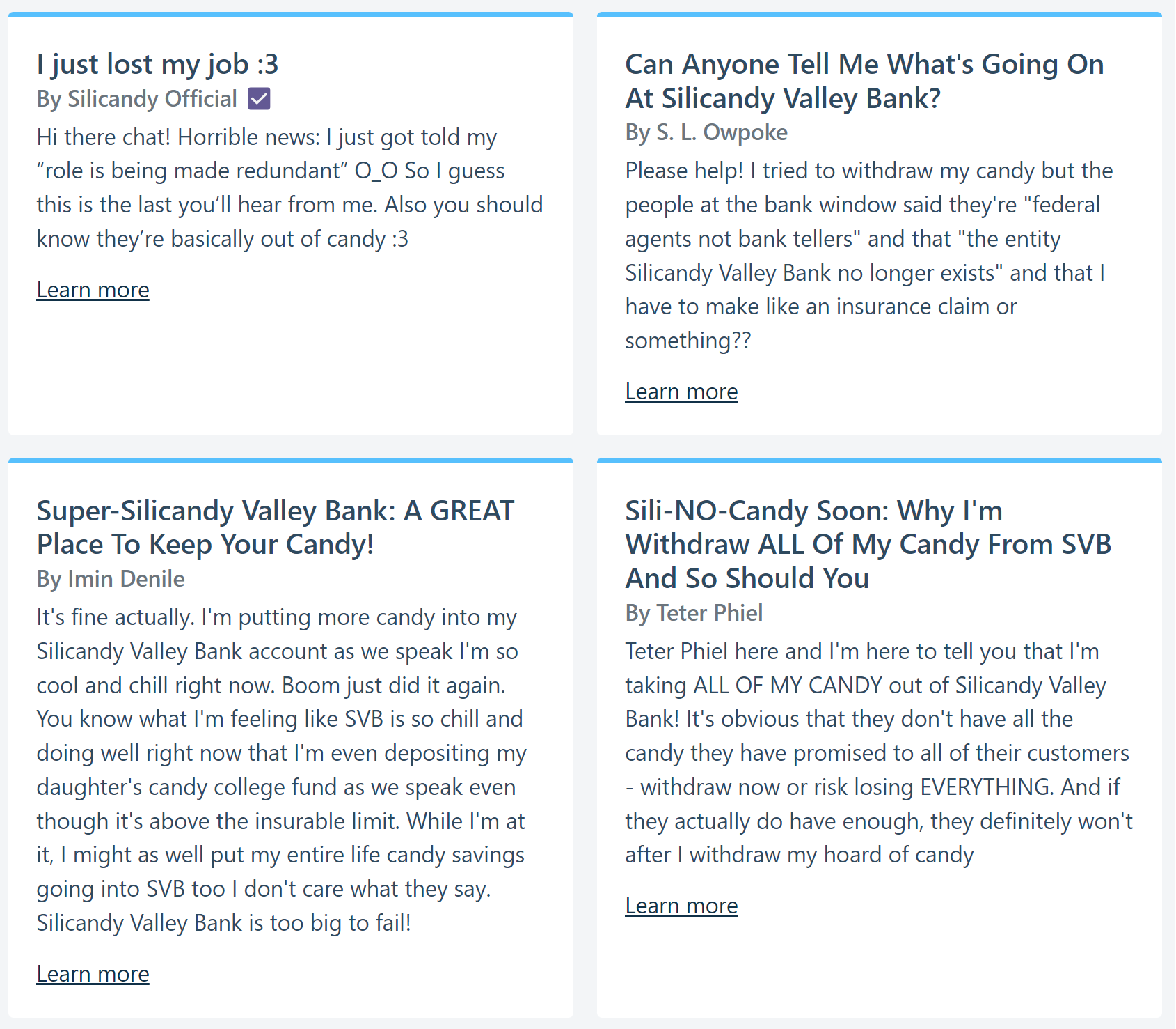
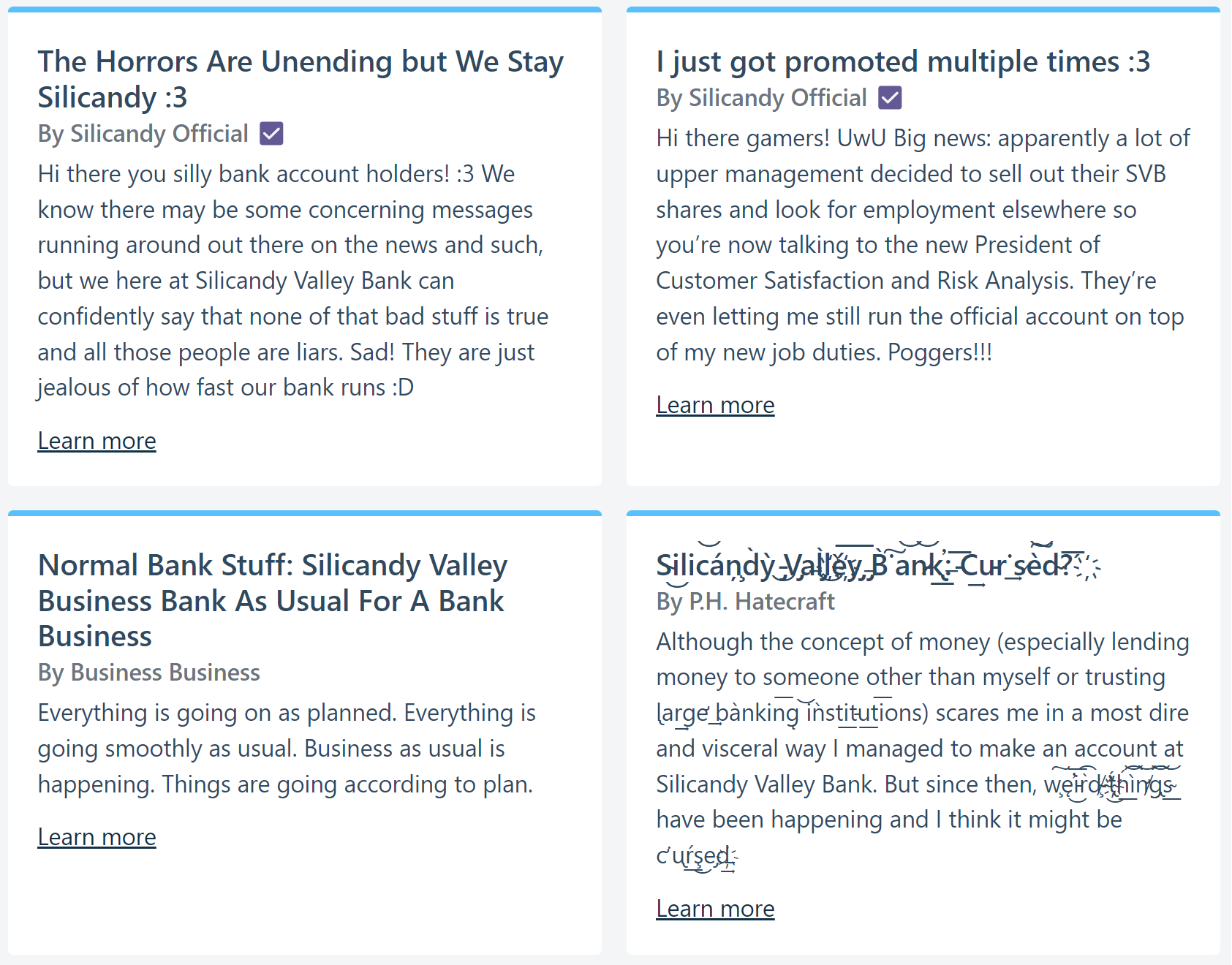
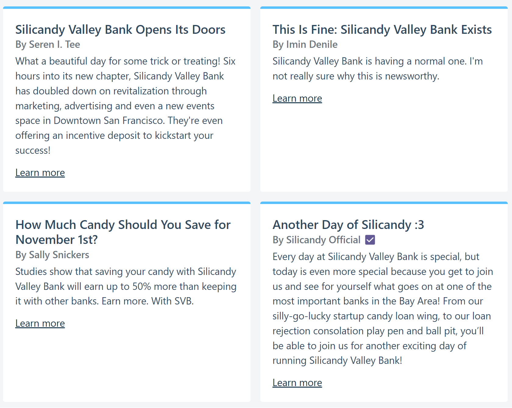
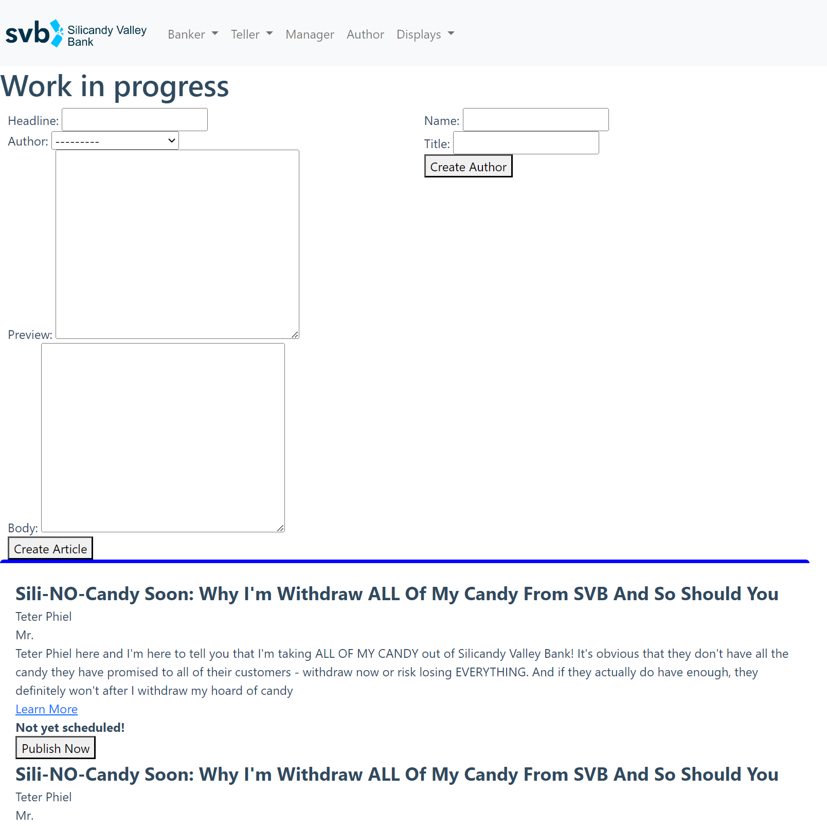
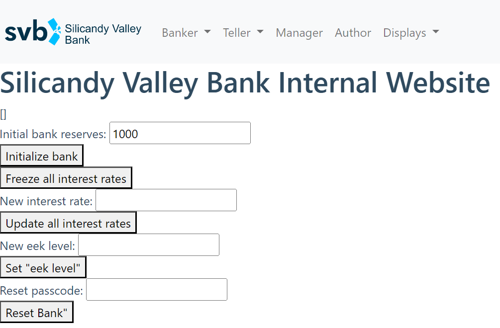
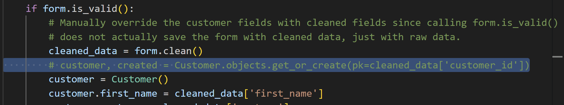
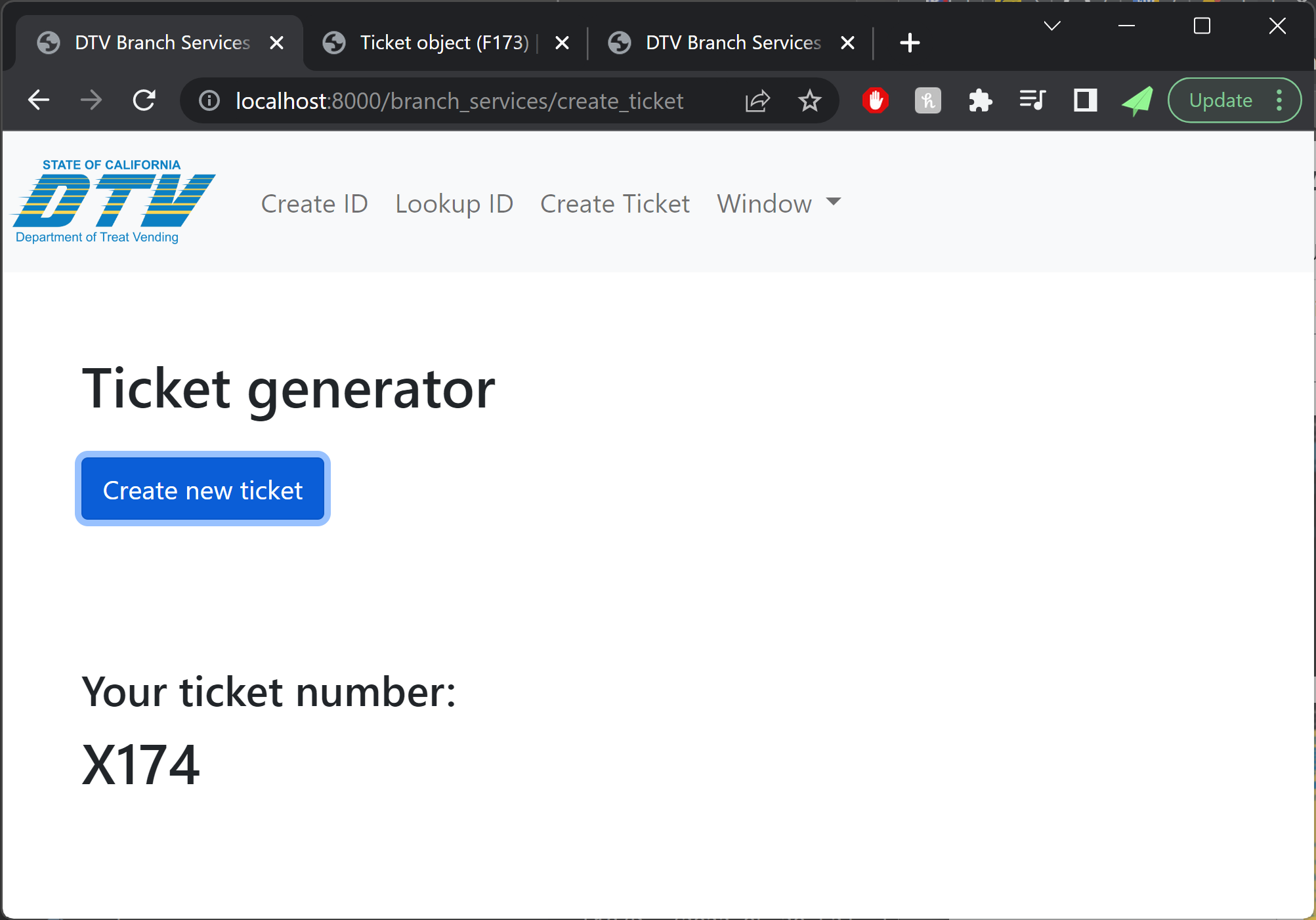
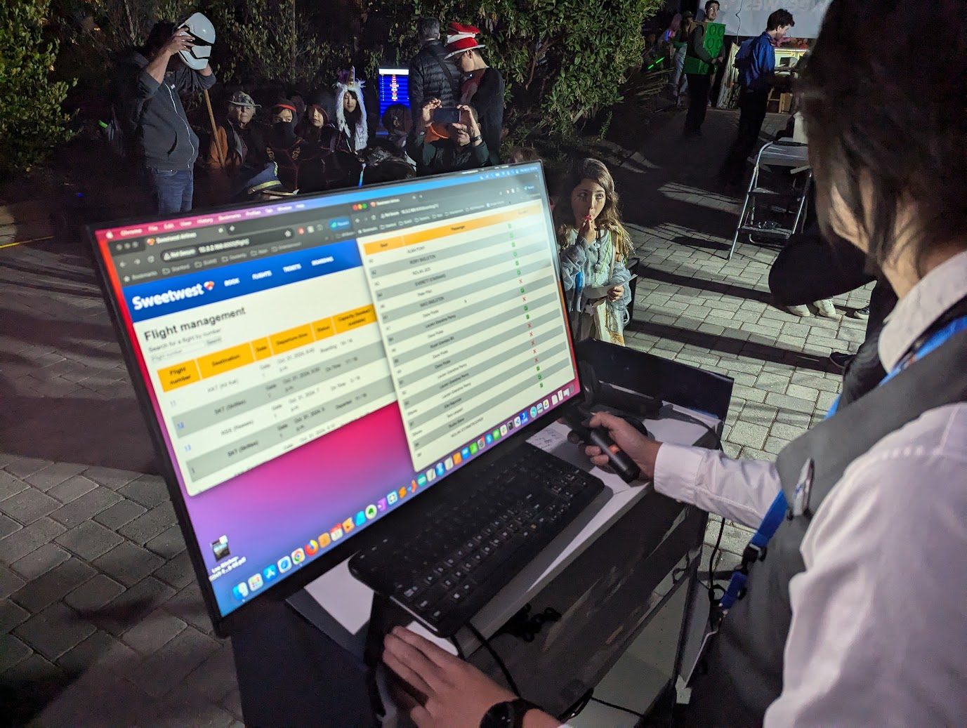
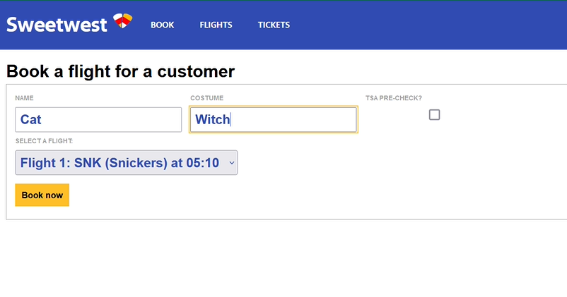
The initial draft of the website came together quickly, so we looked to the Southwest Airlines website for…inspiration in our styling and design of the UX. Although these screens would never be used by trick-or-treaters, they were very likely to be seen in passing, used by our volunteers.
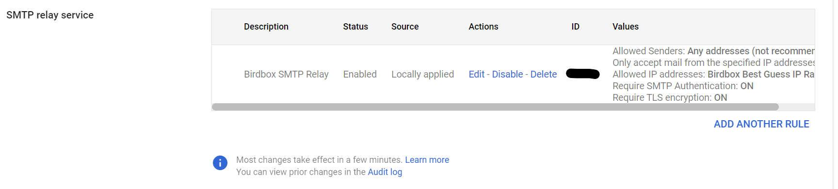
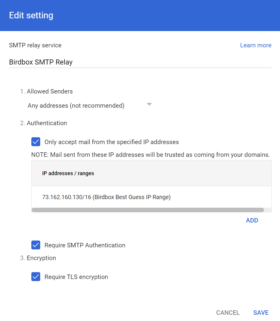
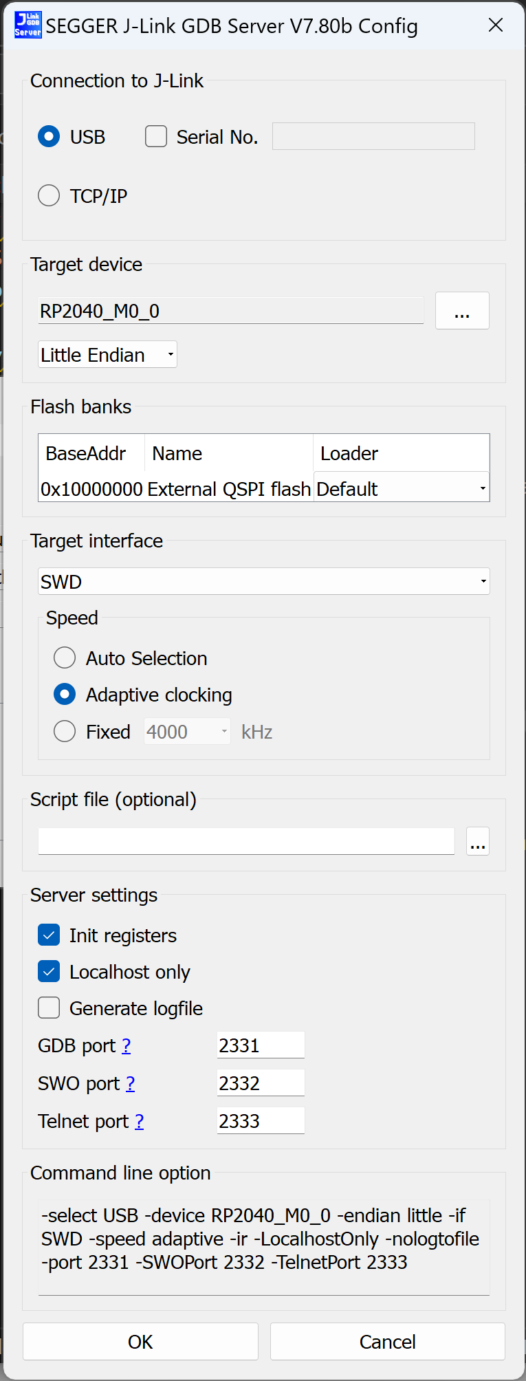
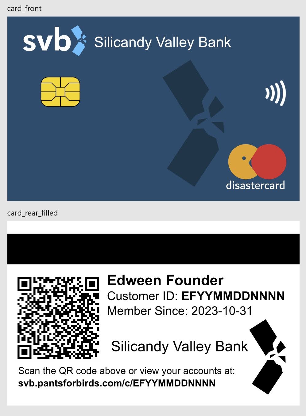
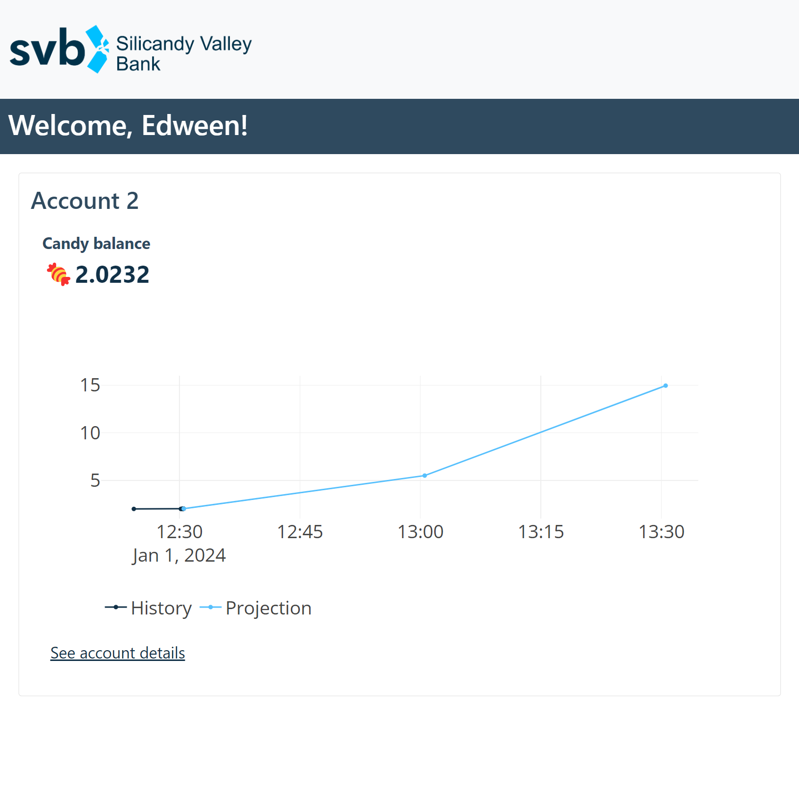
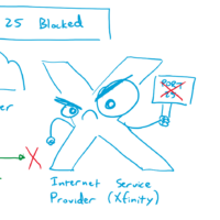
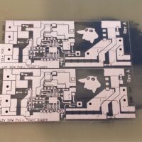
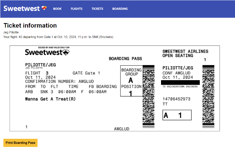
Next on the plate was connecting the data from booking to a printable, dynamically-generated boarding pass. We were able to connect to printers on the same network as the site, and planned to repeat this setup (by creating a special costume network) on the night of Halloween. Our design of the boarding passes paid close attention to detail, and actually encoded relevant data in the boarding pass barcode format (PDF417). This of course begged the question: what if boarding passes could actually be scanned by volunteers, and allow gate agents to call out missing or out-of-order trick-or-treaters?
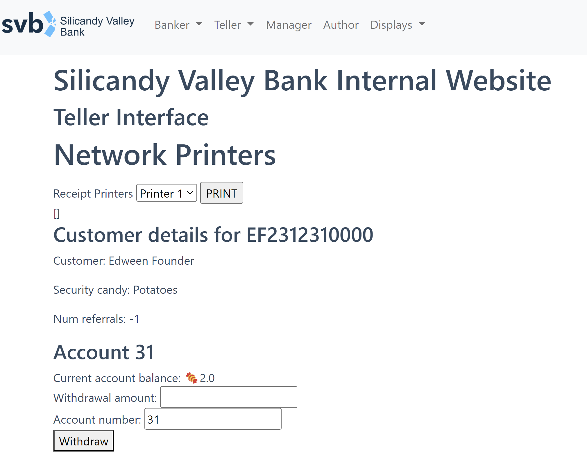
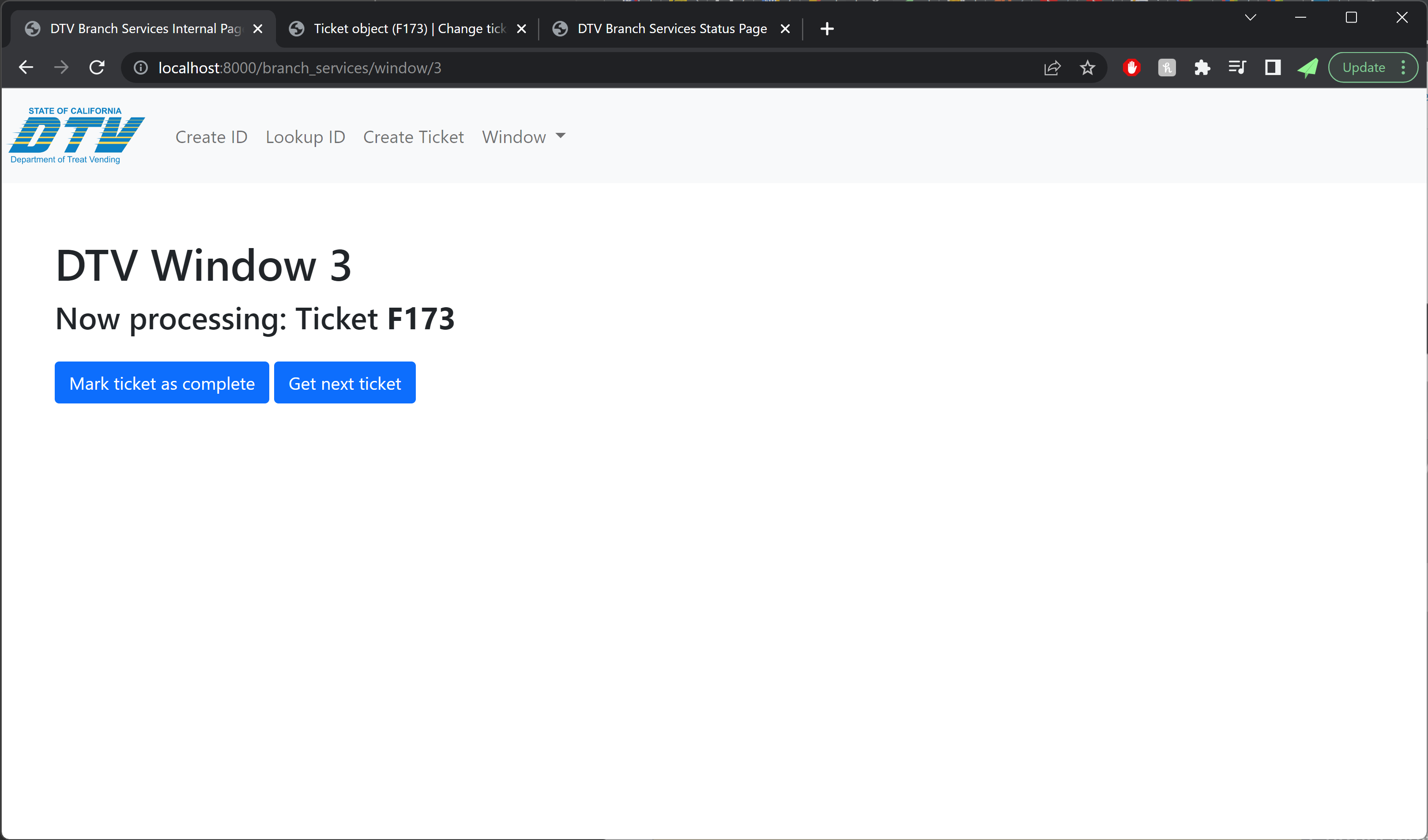
Over the last week prior to Halloween, we added a flurry of boarding and gate-agent related features. The final product allowed gate agents to scan continuously without having to use any mouse or keyboard input, and it also surfaced very specific error messages to support the agent in performatively berating trick-or-treaters for whatever had caused their ticket to be rejected.
IT Systems: Technical Details
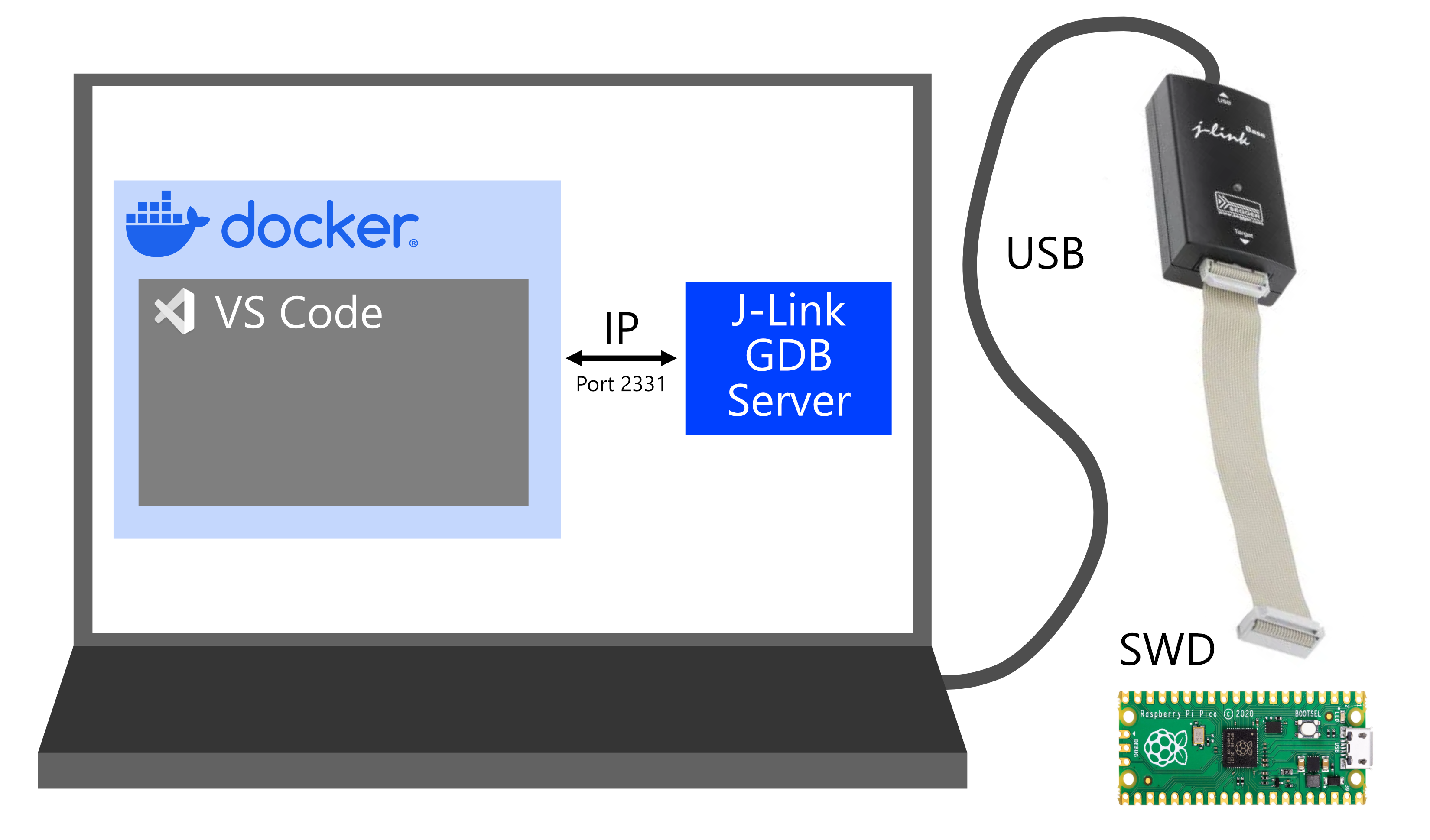
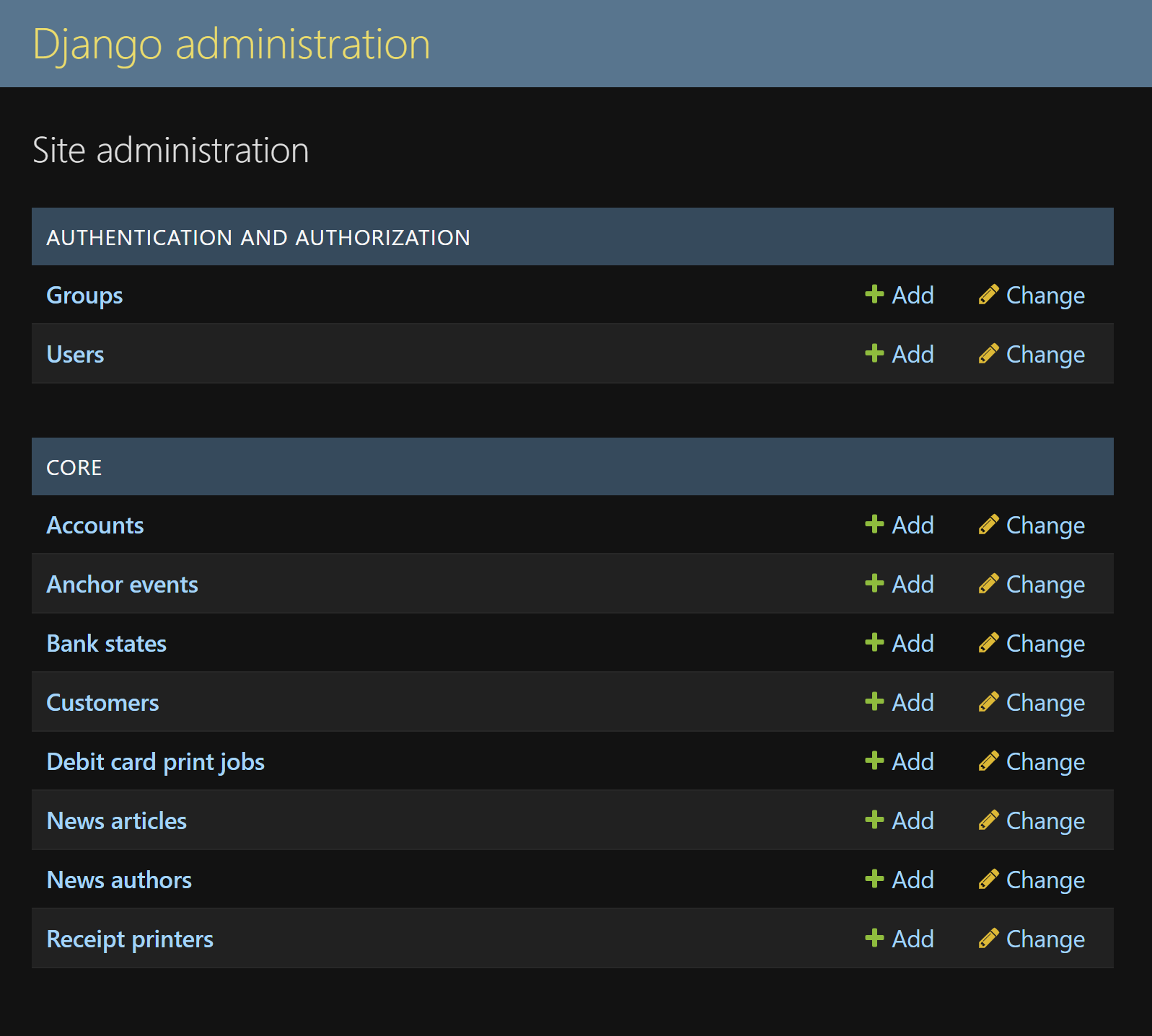
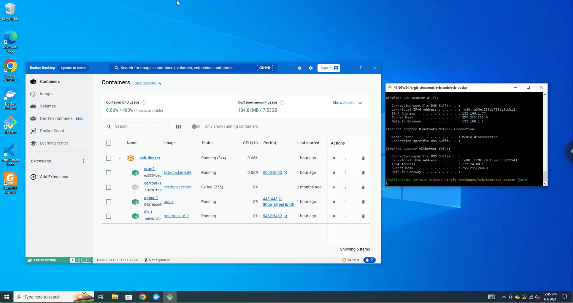
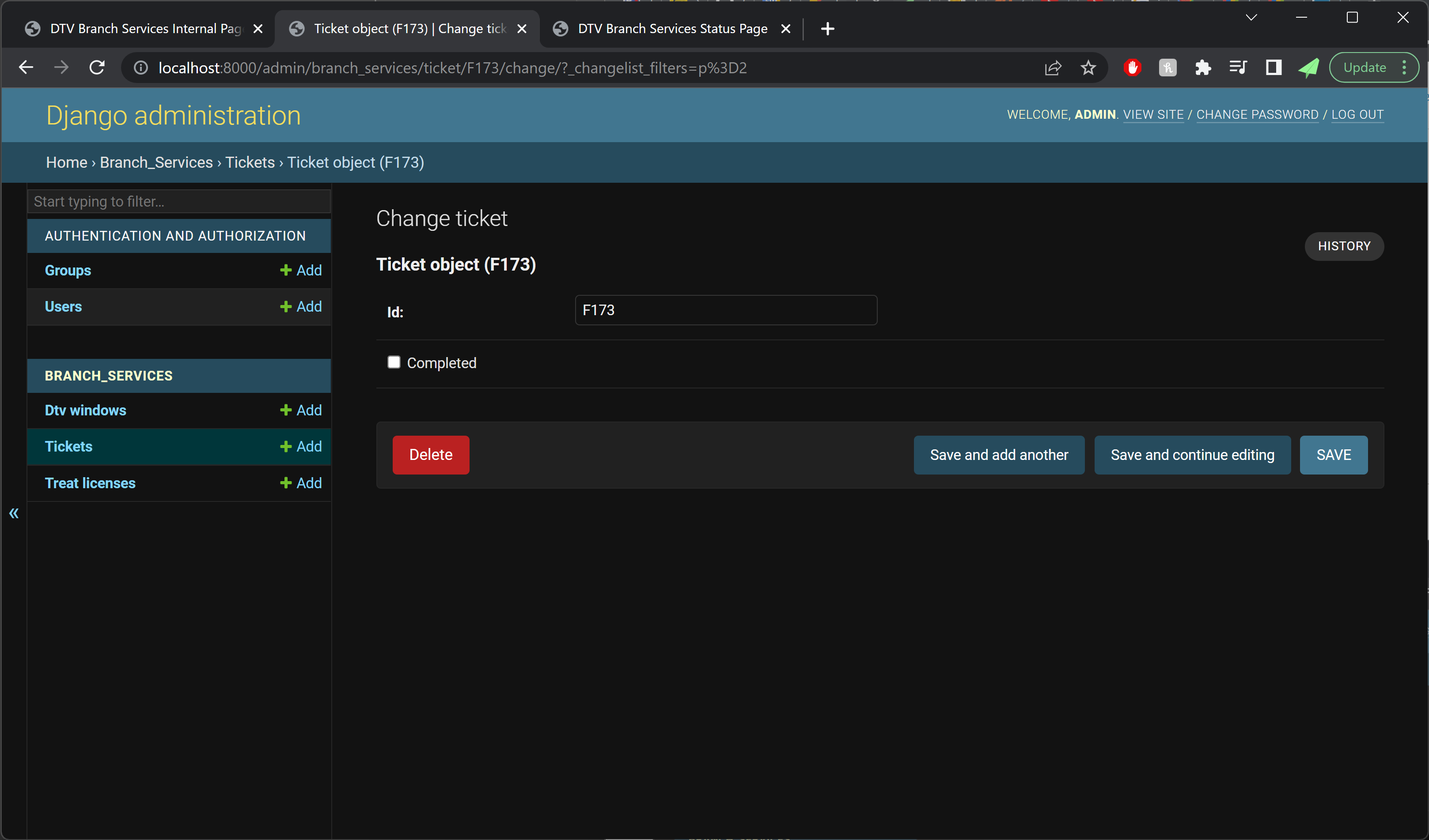
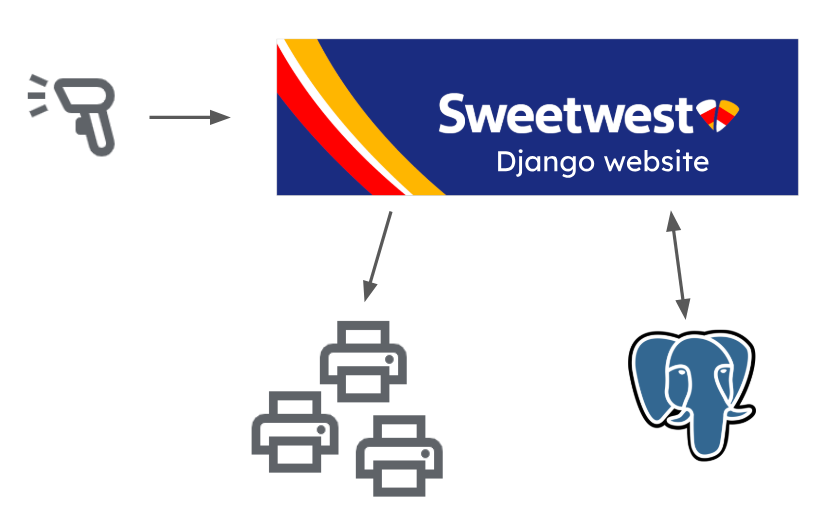
The website was built in Django, with some simple vanilla TypeScript for any frontend pages requiring dynamic behavior. Since the project used Docker Compose, it was straightforward to add a Postgres container as our database. Label printers on the same network as the website deployment were sent boarding pass print jobs, and the ordinary text output from a barcode scanner was used by the “gate agent” volunteer to track “passenger” boarding.
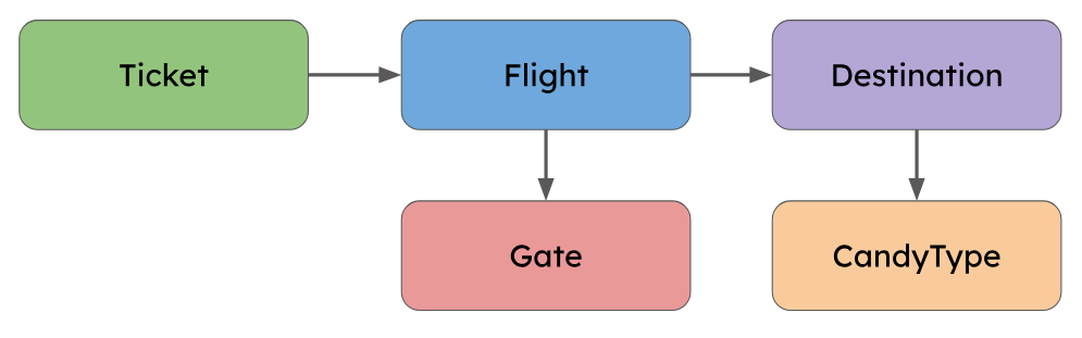
The data model was designed fairly early on to be accommodating of many potential future changes. Because of this the final model was somewhat over-normalized for the actual night-of-Halloween demands.
For example, the initial schema included a “Gate” model, which would allow flights to be mapped to any number of different gates. However, since our final prop layout only included one boarding area, we only ever needed to define a single gate, making the Gate model superfluous.
IT Systems: Night of Halloween
On Halloween night, we had a much more capable system than we had initially planned for. So of course it was time to introduce a bunch of last-minute feature requests that violated fundamental assumptions of the system!
About two hours before showtime, we got a new (huge, schema-upending) feature request: “we need to add standby tickets.” We had previously gone back-and-forth about how best to handle no-shows, and decided to just fly without those passengers. Adding standby would be an excellent fix, but would require major changes to the booking, boarding, and flight display pages, so we had previously written it off as too much work. With minutes to spare, we converted our existing system into one that was compatible with standby, involving a lot of big changes:
- The largely unused TSA pre-check database field was renamed and modified to capture standby info
- Booking was updated to ignore standby tickets
- The boarding pass generation was updated to indicate standby in the boarding position field
- Boarding was updated to let standby tickets be scanned in and counted as part of the flight capacity
In either a minor miracle or a product of our clean and robust codebase, the standby feature worked perfectly at launch!
Even the best-planned project doesn’t always escape its first use unscathed, and over the course of the night we made a few more changes for balance on the fly (pun not intended):
- Reduced boarding time to 7 mins from 15 mins (trick-or-treaters were waiting in the gate area for longer than was fun)
- Added more info about boarding to the gate agent page (gate agents needed to stay informed about delays to takeoff time)
- Hid departed flights from the flight display page (it was already difficult to get across the concept of booking a ticket for a flight, and having departed flights on there just confused guests further)
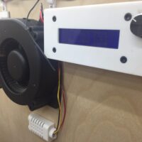
IT Systems: Terminal Audio
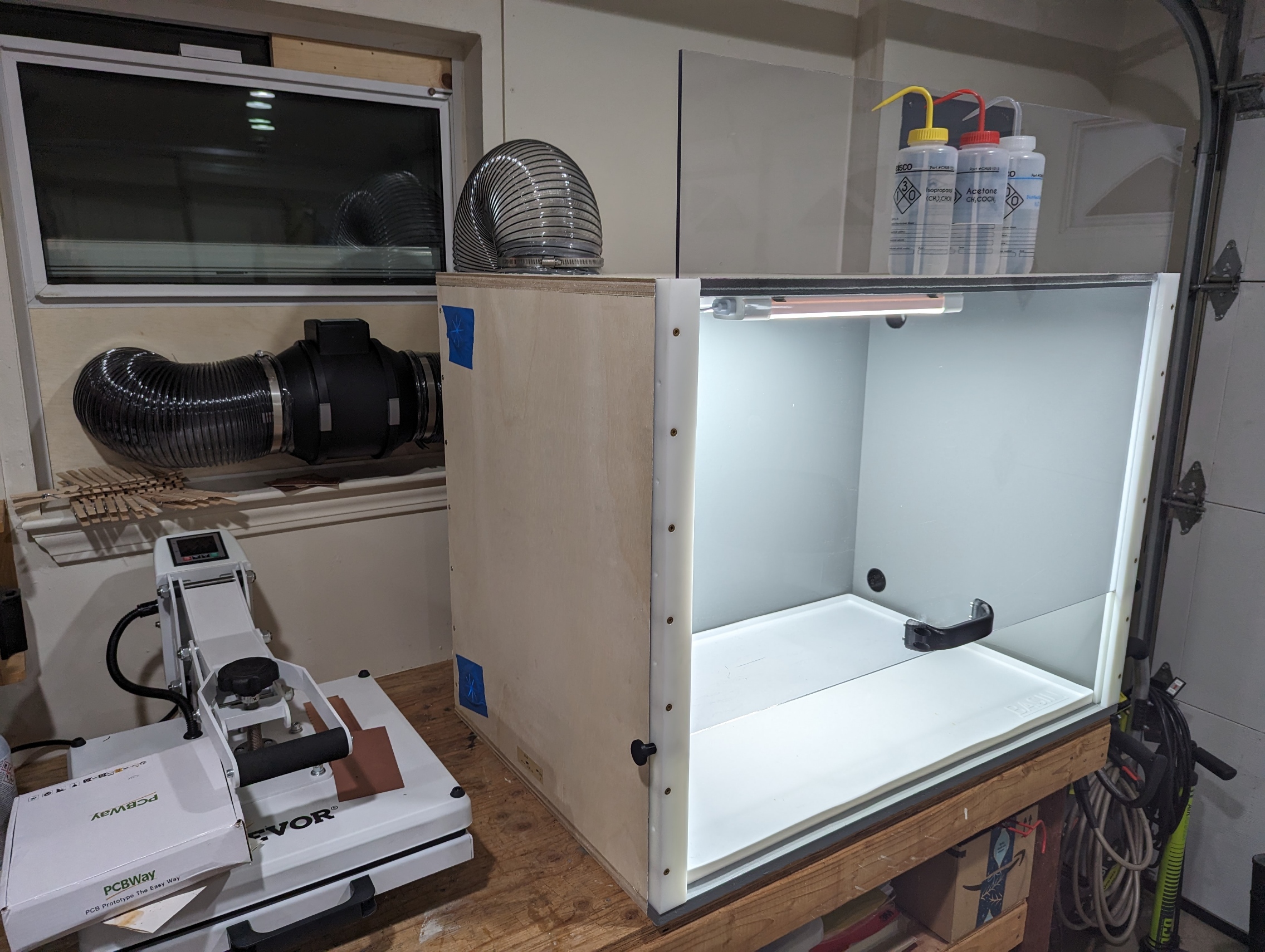
For this part of the project, we started with a list of critical features that the audio system really should have in order to provide the best experience. Last year we found that a modest single 65W loudspeaker was not really sufficient to cover the full driveway area, so we decided to upgrade to two iOn Pathfinder 320 portable speakers. These each have 3x the power, and take both bluetooth and aux input to help leave our connectivity options open. For inputs, our plan involved announcements from both the attendant at the boarding counter, interspersed with other miscellaneous announcements by a staff member at a variety of locations, so we settled on the “JBL Wireless Microphone Set” (that’s literally the part number). These choices ended up performing quite well, with plenty of volume from the speakers, and convenient announcements from anywhere with the mics.
To tie the inputs and outputs together, we started by making a list of critical features that the audio mixer system really should have in order to provide the best experience:
- Continuously playing background ambiance (airport lobby music)
- Slightly obnoxious attention chime right before an announcement
- Live microphone audio with acceptably low latency
- Auto-ducking the ambiance when the microphone input is active
Dedicated hardware for performing these types of audio processing functions does exist, but brief research suggested that they start at roughly 4 figures, so we decided to try rolling our own solution. Music producers commonly use a type of software called a DAW (digital audio workstation), and many of these also come with tools for giving a live performance, including real time multi-channel mixing with a huge variety of software effects.
One of the big challenges with doing anything related to live audio on a computer is latency, and generally producers will use an Apple laptop because a huge amount of development effort has been put into making audio latency on MacOS as low as possible. However, Linux is able to achieve a comparable level of performance with the right drivers, though perhaps at the cost of increased effort to set it up. For this project we are very lucky to have the excellent 60 day free trial of REAPER available, which supports every major OS including even Raspbian.
As with any other project involving Linux, there are some specific details that were very important to achieving the functionality we wanted. Linux has several different audio drivers for specific use-cases, and the general purpose one is called pulse-audio. This works very well for all of the usual tasks like watching youtube or having a telecom, but doesn’t have the best performance with regards to latency. This is where REAPER will instead prefer the ALSA driver, which is optimized to get the best performance out of your audio hardware, but is much less compatible with various software than pulse-audio. For this project we wanted to mix audio from both the background ambiance youtube playlist, and the low-latency live microphone input, and this required a creative solution to bridge the gap between the two sound drivers.
Starting with the lobby music ambiance, it was easiest to play it on youtube in the browser, which pipes it to one of the system outputs using pulse-audio. It might be possible to use some complex software solution to loop that back and redirect it as an ALSA driver input, but it was far simpler to just add another audio input to the system and loop it back in hardware externally. It is very important to note that for multiple inputs ALSA requires them all to be part of the same device, otherwise there are some obscure sampling clock misalignment issues that were not worth digging into at the time. To make this work, it is most convenient to buy a USB audio interface with multiple inputs, and the M-Audio M-Track Duo was the cheapest reasonably functional option for this.
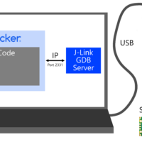
With that figured out, our system ended up looking something like this:
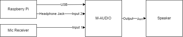
After some testing, we found that the speakers had a lot of latency when connecting over bluetooth, so we hardwired them with an aux cable splitter from the audio interface output. Also the raspberry pi 4 that was originally used had some occasional lag and stutters, so we swapped it with an Intel NUC with Ubuntu on it and everything worked great.
The setup in reaper is a bit contrived, but here is an overview of each channel:
- Channel 1: This is set to be a mono input, and receives from input 1 of the audio interface, which is what the microphone receiver is plugged into. Raw audio directly from the microphones shows up here.
- This channel is configured to send to channel 3, and to the master channel.
- This channel also has compression plus high- and low-pass filters to remove the top and bottom frequencies, for better approximation of an airport PA system
- Channel 2: This is set to be a mono input, and receives from input 2 of the audio interface, which is what the headphone jack of the NUC is plugged into. Audio from our ambient music playlist shows up here.
- This channel sends directly to the master channel
- This channel has a gate plugin on it with a very specific configuration. First, the detector input is set to auxiliary inputs (which are forwarded from channel 3 below), and the Invert Gate option is selected. Then, Send midi on open/close is selected, for controlling the airport chime.
- This channel also forwards only its midi outputs to channel 4
- Channel 3: Placeholder channel to add extra effects for adjusting the sound gate activation.
- This channel has a reverb plugin to extend the duration of audio it receives from channel 1, since the gate plugin has a maximum hold duration of 1000ms, which is a bit short for this application.
- This channel also sends track 1/2 of its audio to the auxiliary input (track 3/4) of channel 2, for use in the gate plugin as the trigger source
- This channel specifically does NOT send to the master channel, as the output is only intended for the gate plugin
- Channel 4: This just has an instance of ReaSamplOmatic5000 on it that is configured to play the airport chime sound clip once on any midi note activation, sending straight to the master channel.
This describes the configuration in theory, though there were several undocumented tweaks made in production to make things run smoother. The parts that I remember:
- Some inexplicable hum was showing up on the microphone input, so one of the team members figured out how to use the ReaFir FFT plugin to build a noise profile of the hum and then subtract it from the input, which worked very well.
- There was some issue with the channel 3 gate trigger extension technique, and eventually we just disabled the reverb and somehow things worked (we’re still not sure why).
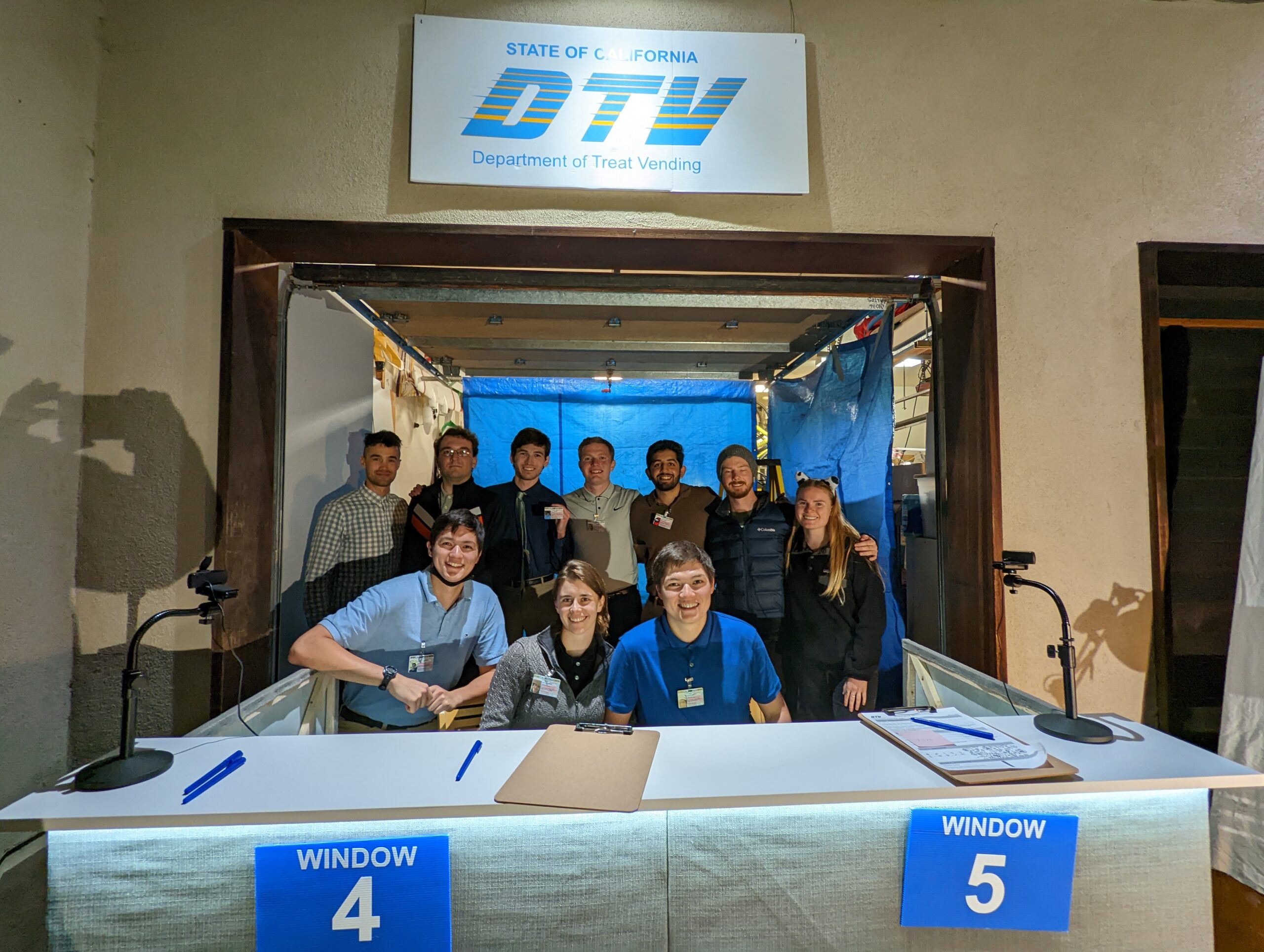
Conclusion
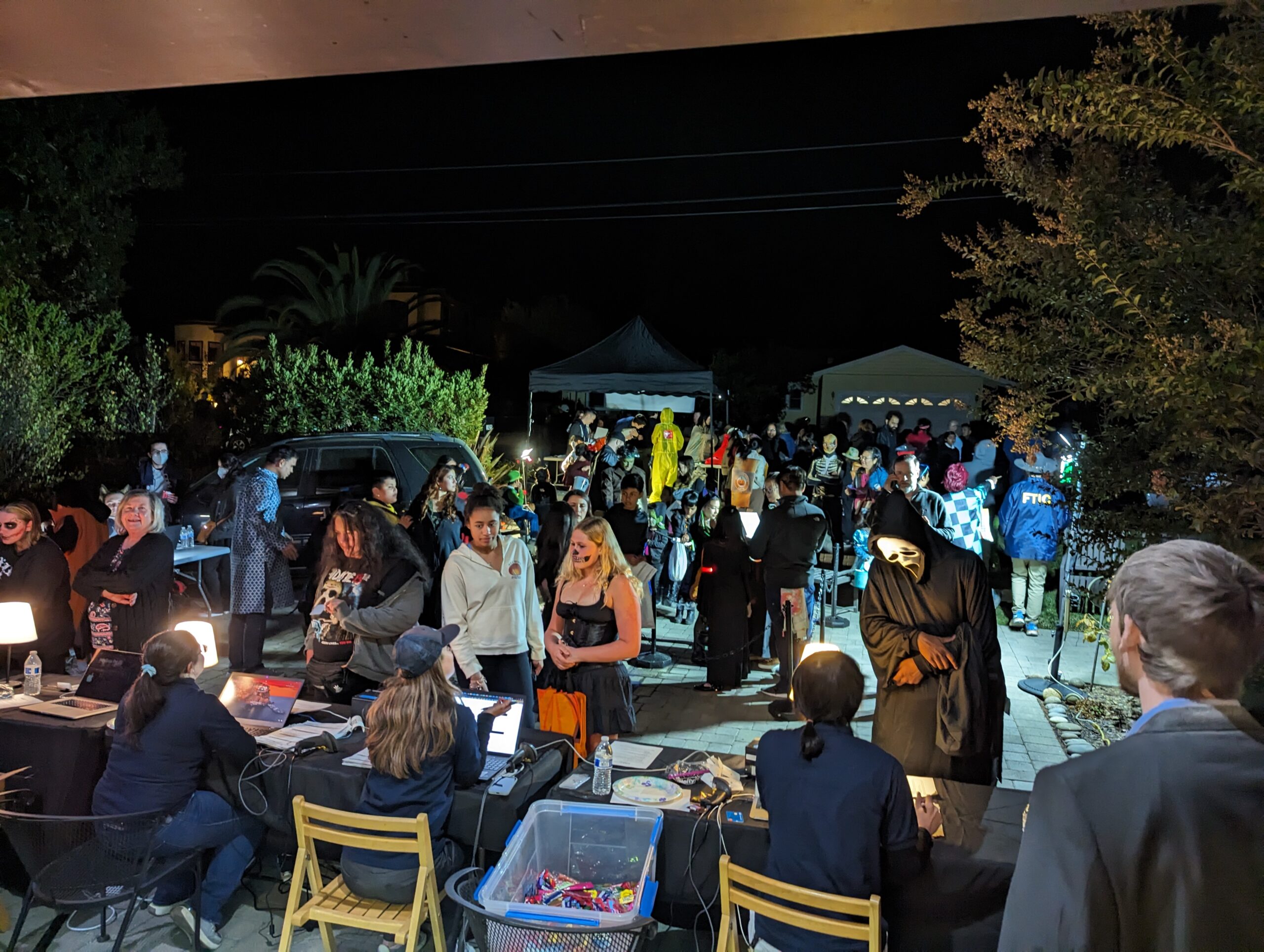
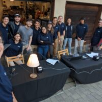
This year’s Halloween costume was by far our craziest idea yet, and it was absolutely magical to watch everything everything come together thanks to the efforts of our (largest so far) team of dedicated volunteers. We handed out over 400 full size candy bars to passengers across 25 scheduled flights, and it took a few hundred hours of coding, gluing, spray painting, heat pressing, crafting, and debugging to make it happen. Fortunately, every volunteer that we’ve asked seems to agree: it was totally worth it!