I’ve always enjoyed cooking, especially Asian food (lots of influence from my mom’s side of the family in Wuhan) and slow-smoked barbecue (idk it’s tasty). One day in the summer of 2021, Caitlin (my Significant Other), Kenneth (my brother), and I stumbled into a strange cocktail of boredom and hubris and decided to start a farmers’ market stand specializing in hot food of the Asian-American fusion variety.
Chapter 1: Haha What If We Ran a Farmers’ Market Stand
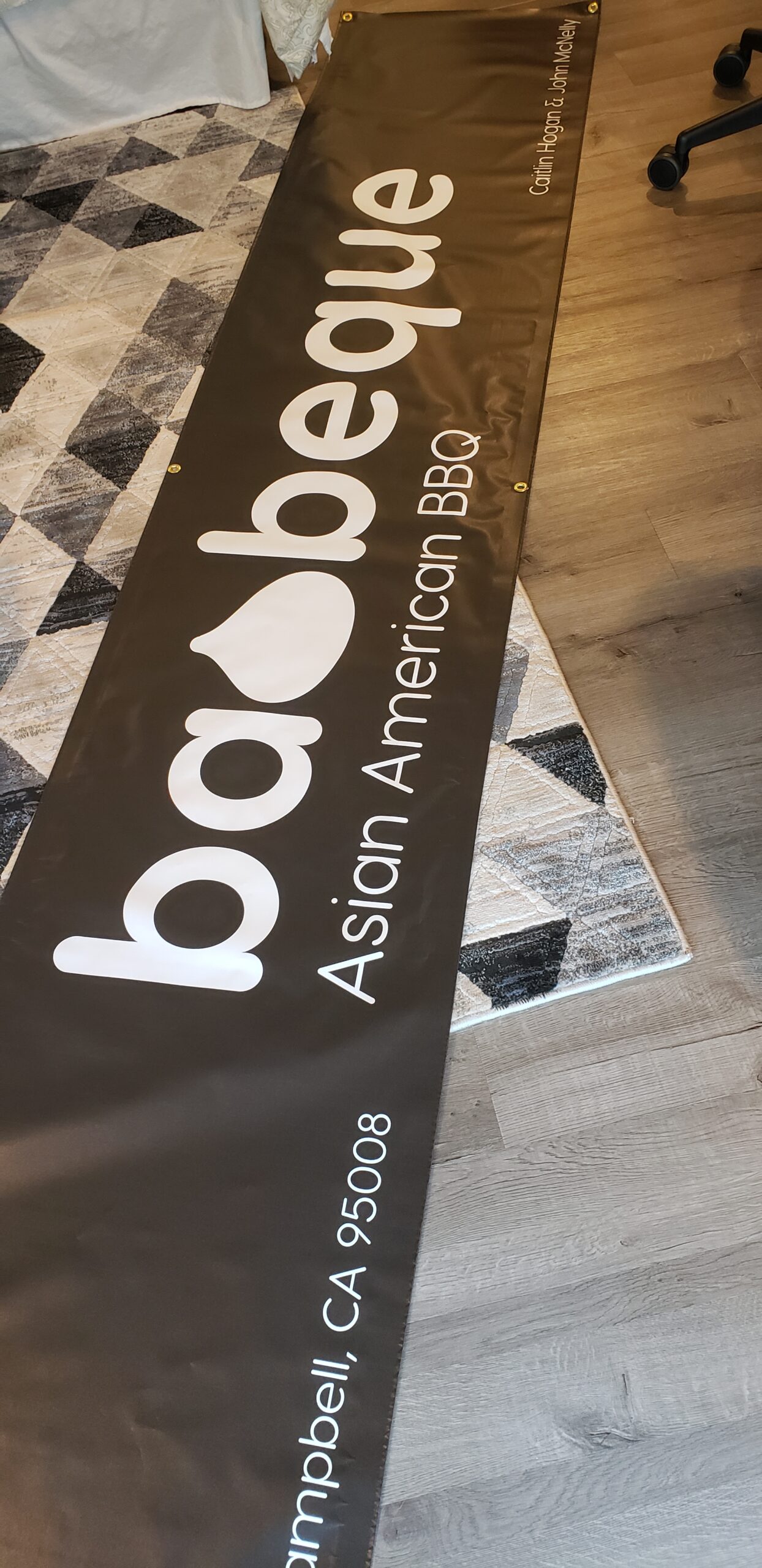
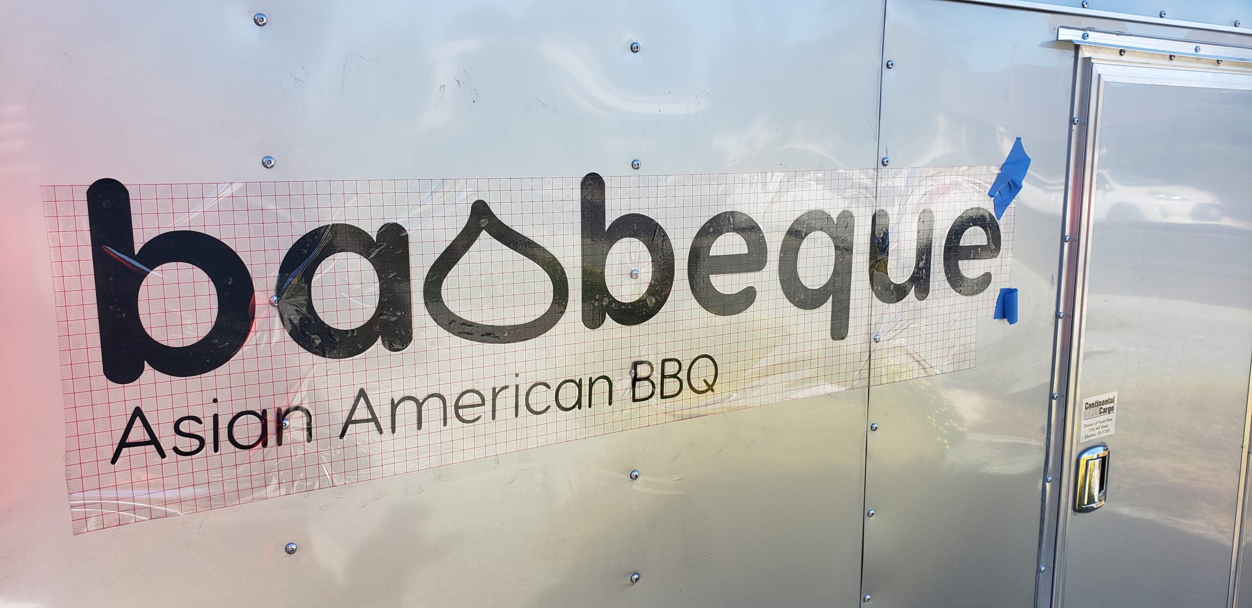
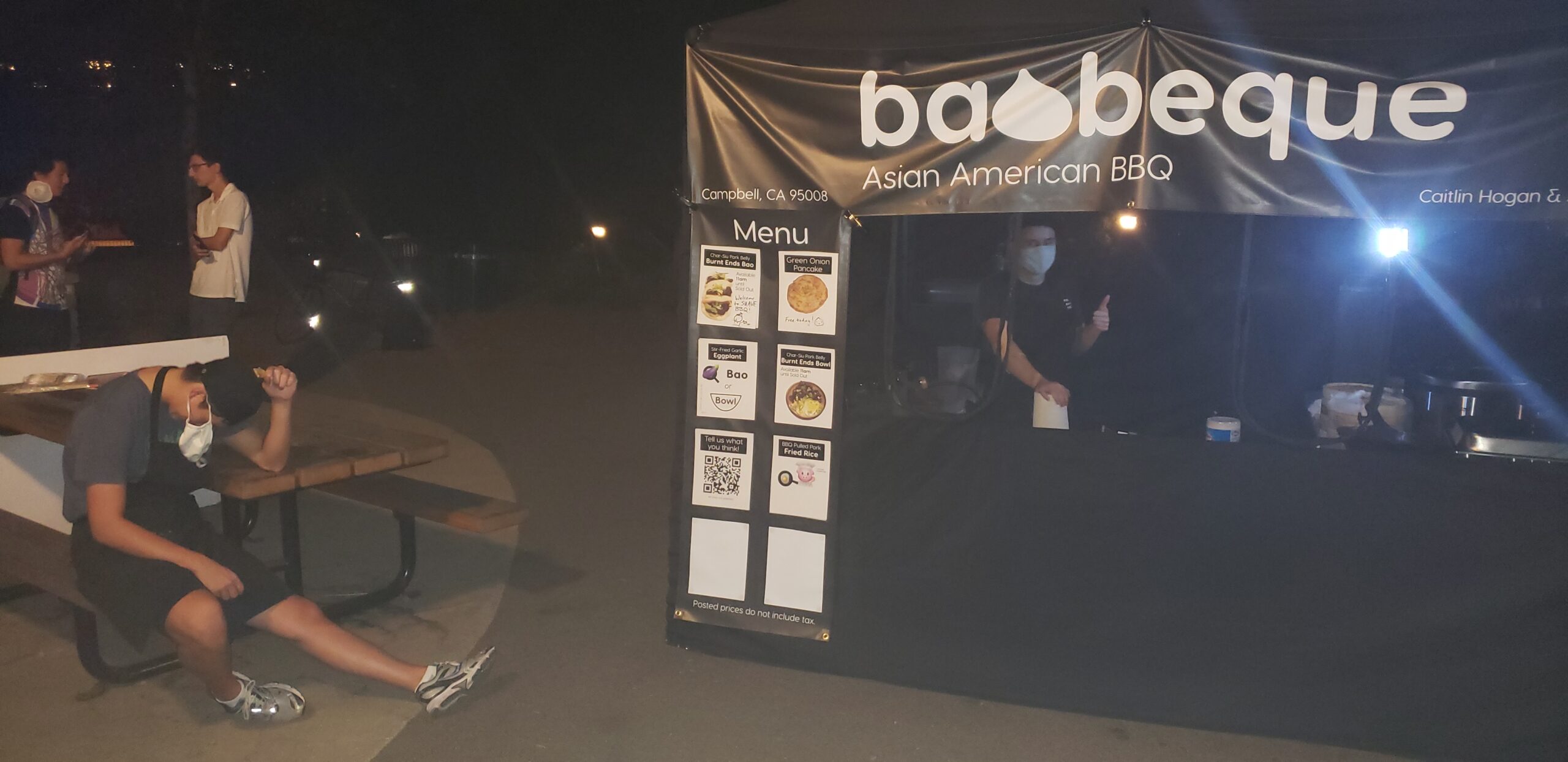
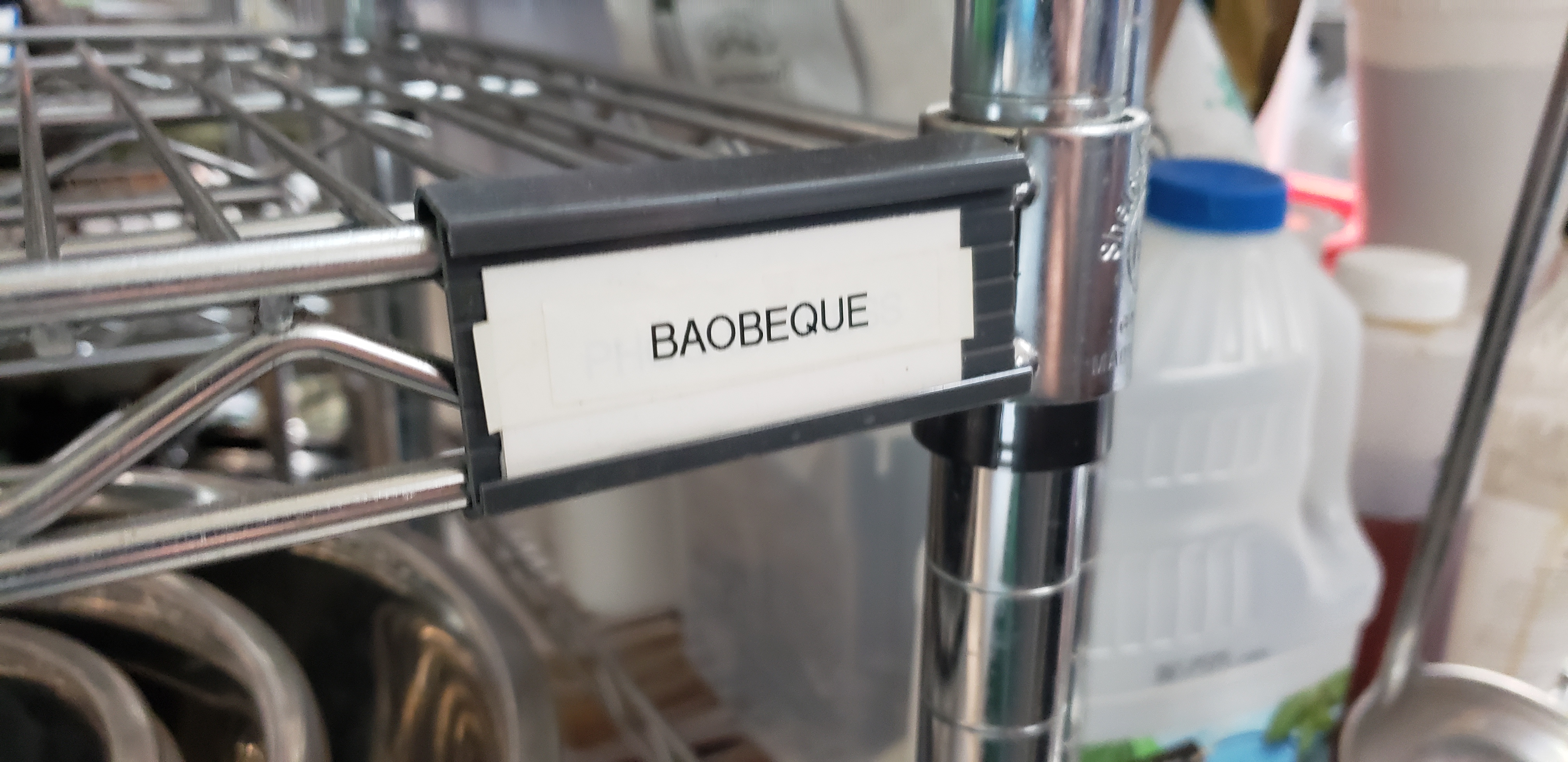
In truth, we thought of the name first, Baobeque, and thought it was a fun enough name that it was worth thinking up a menu for a farmers’ market stand with that name, you know, as a joke. And cooking test recipes for it, you know, as a joke. And filing for the Fictitious Business Name. And registering for a resellers’ certificate and building a budget and starting a sales tax account with the CDTFA and getting a federal EIN and shopping around at commissary kitchens and writing a business plan and applying to farmers’ markets. For the joke. Haha so funny what if we actually ran a farmers’ market stand that would be so crazy we’re all engineers we have like no time.
Chapter 2: Why Won’t Anyone Let Us Run a Farmers’ Market Stand
On the outside, Farmers’ Market food stands look like a great idea for a business. They serve simple items, have low capital costs, and absolutely print money. For the cost of a tent and some minimal fees paid to the farmers’ market, you can have access to a vast number of potential customers who are willing to pay relatively high prices for unique and interesting food. So why aren’t there more of them?
It turns out that Farmers’ Markets are not just a collection of stands competing with each other on one street. The whole Farmers’ Market is carefully curated, competing with other Farmers’ markets in the area to attract the most customers, retain the best vendors, and secure the best venue. Farmers’ Markets are run by market managers who are in charge of admitting vendors to the market, collecting fees for the markets’ parent organization (usually one organization will run a number of different markets spread out throughout a large area across different days of the week, so that vendors and market staff can work multiple days a week). Because space in each farmers’ market is limited, market managers have to pick and choose which vendors are allowed a spot. In order to keep vendors happy (by avoiding too much competition in each product catrgory), and in order to provide market customers with a variety of choices, market managers usually limit hot food stands to one per specific food category (e.g. there can only be one hamburger stand). If the market is especially large, or there is extra demand for a certain category of food (e.g. artisan bread is super popular), market managers may allow a larger number of similar food vendors. If two vendors overlap but not entirely, market managers may artificially restrict the menus of the two vendors in order to resolve the conflict by reducing competition (e.g. if there’s a noodle vendor that also serves dumplings, they may not be allowed to sell dumplings if entering a market with a pre-established dumpling vendor).
All of this is to say, Farmers’ Markets aren’t just a collection of people who showed up with tents. Each vendor in the market is hand-picked to cater to the most likely tastes of the local clientelle, while providing mutual benefits and minimally destructive competition to other vendors in the market. Kind of like some kind of artificially constructed coral reef, if the corals are vendors and the fish are people who get up at the crack of dawn on a Sunday morning looking to purchase expensive produce from a tent outside a Starbucks.
Because of the large number of prospective vendors that want to join a farmers’ market, and the intense selection criteria created by market managers, many applications to join farmers’ markets are denied, and many more are placed on years-long waitlists to stand by in case another vendor drops out. After a number of fruitless applications, Baobeque seemed like it wasn’t going to get into any farmers’ market anytime soon. But, we were convinced that our concept was unique and provided an angle that wasn’t present in our local market, so we pressed on and began to (politely) badger the local market managers about our vendor application whenever we visited their market. After discussing our concept with them and staying engaged in for a few months, we managed to warm them up to the possibility of adding our tent concept to the market, and eventually they asked us for samples of our food (one of the final steps in the application process)! By some miracle, the market managers liked our food, and our application was green-lit and forwarded to upper management for final approval.
Chapter 3: Oh No, We’re Running a Farmers’ Market Stand
Crap crap crap crap quick we gotta get everything ready!
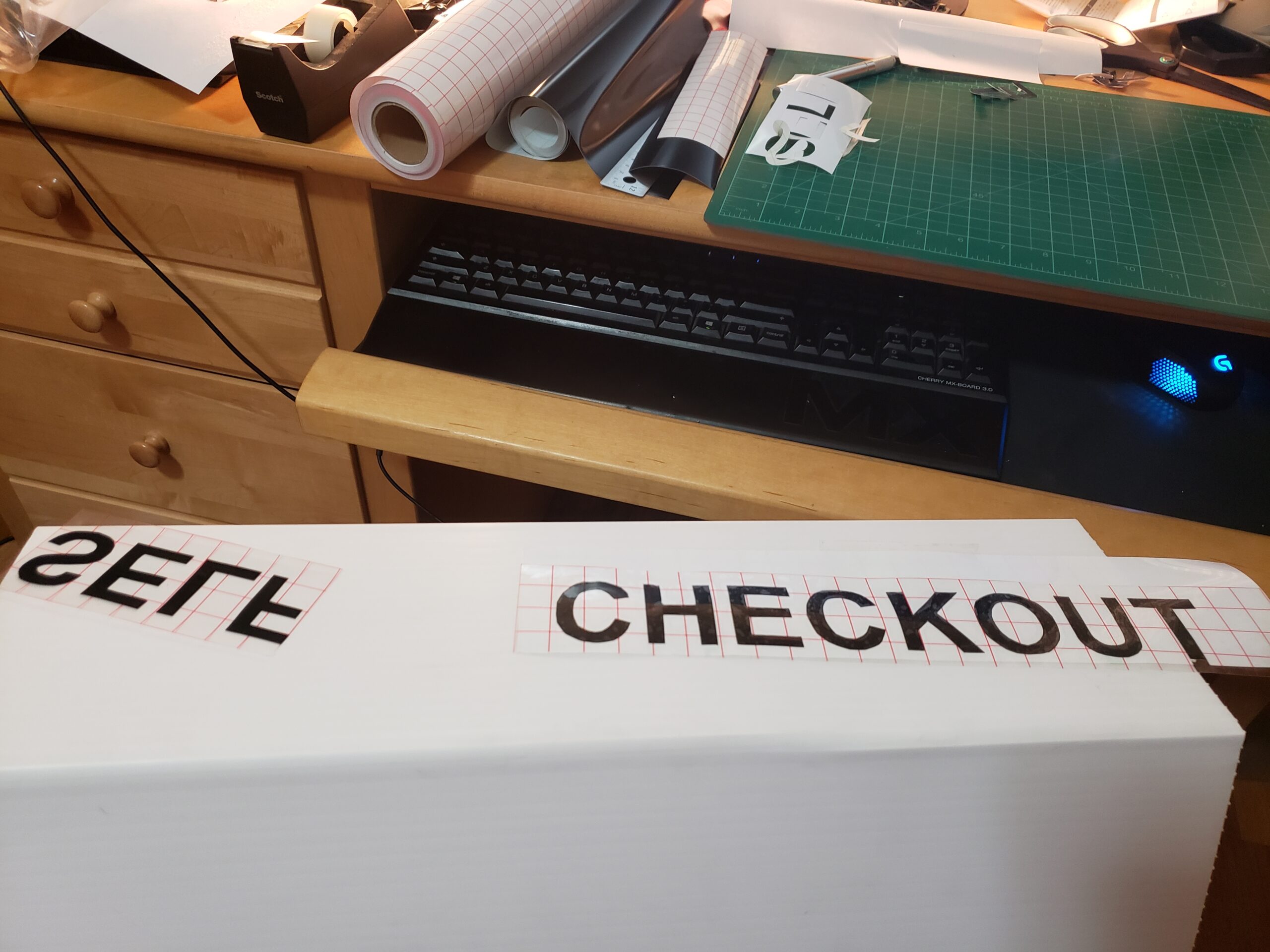
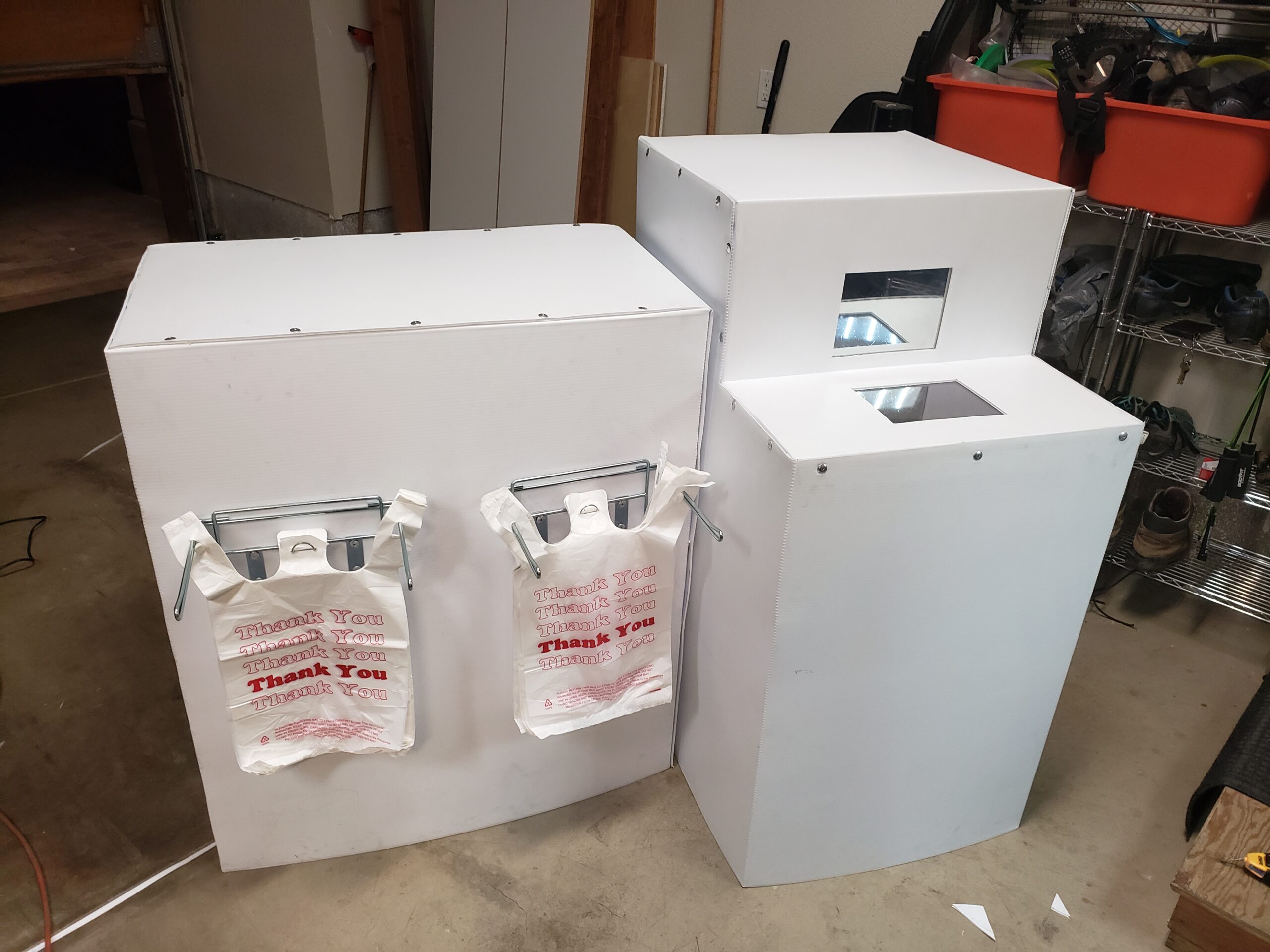
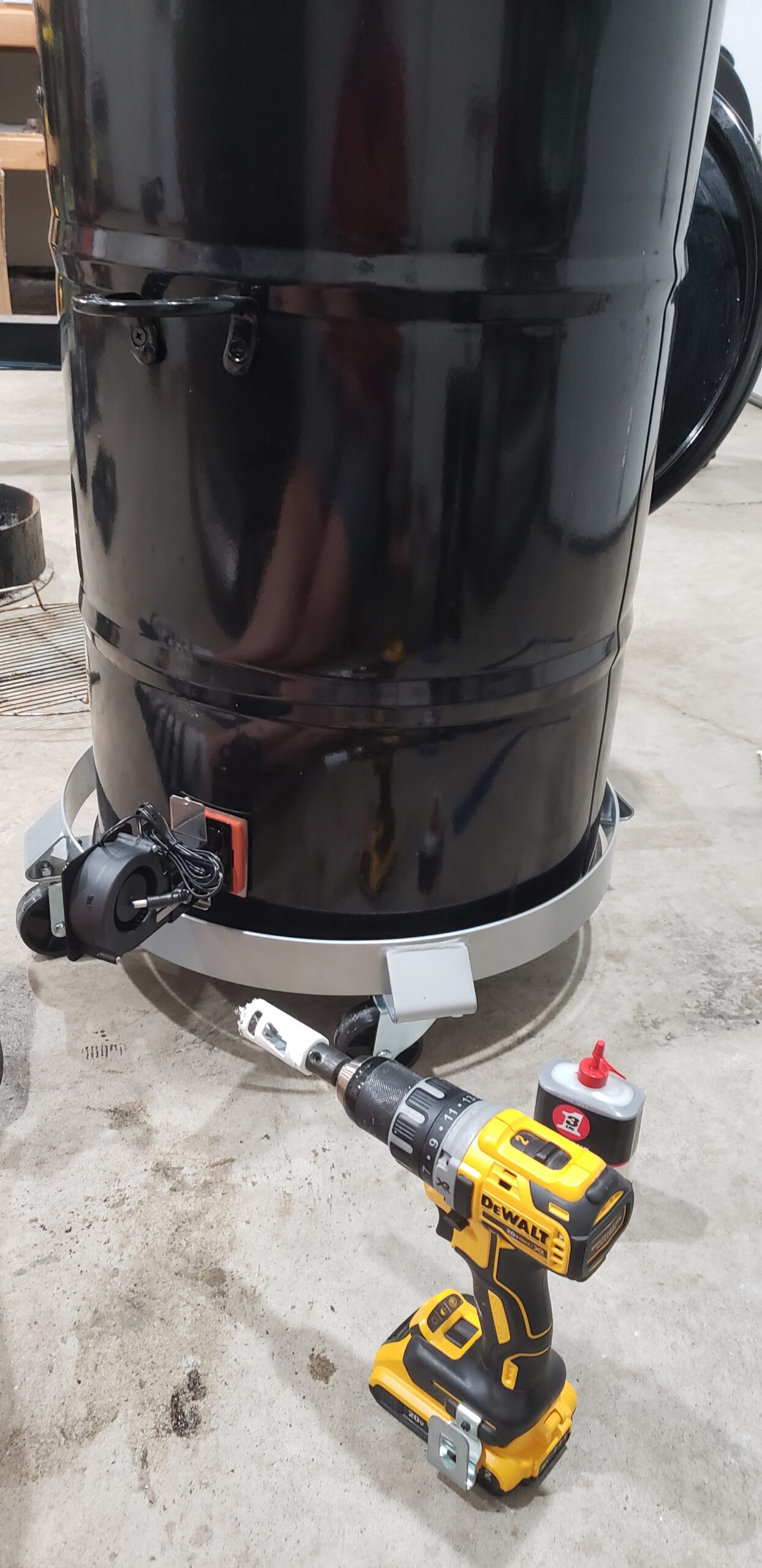
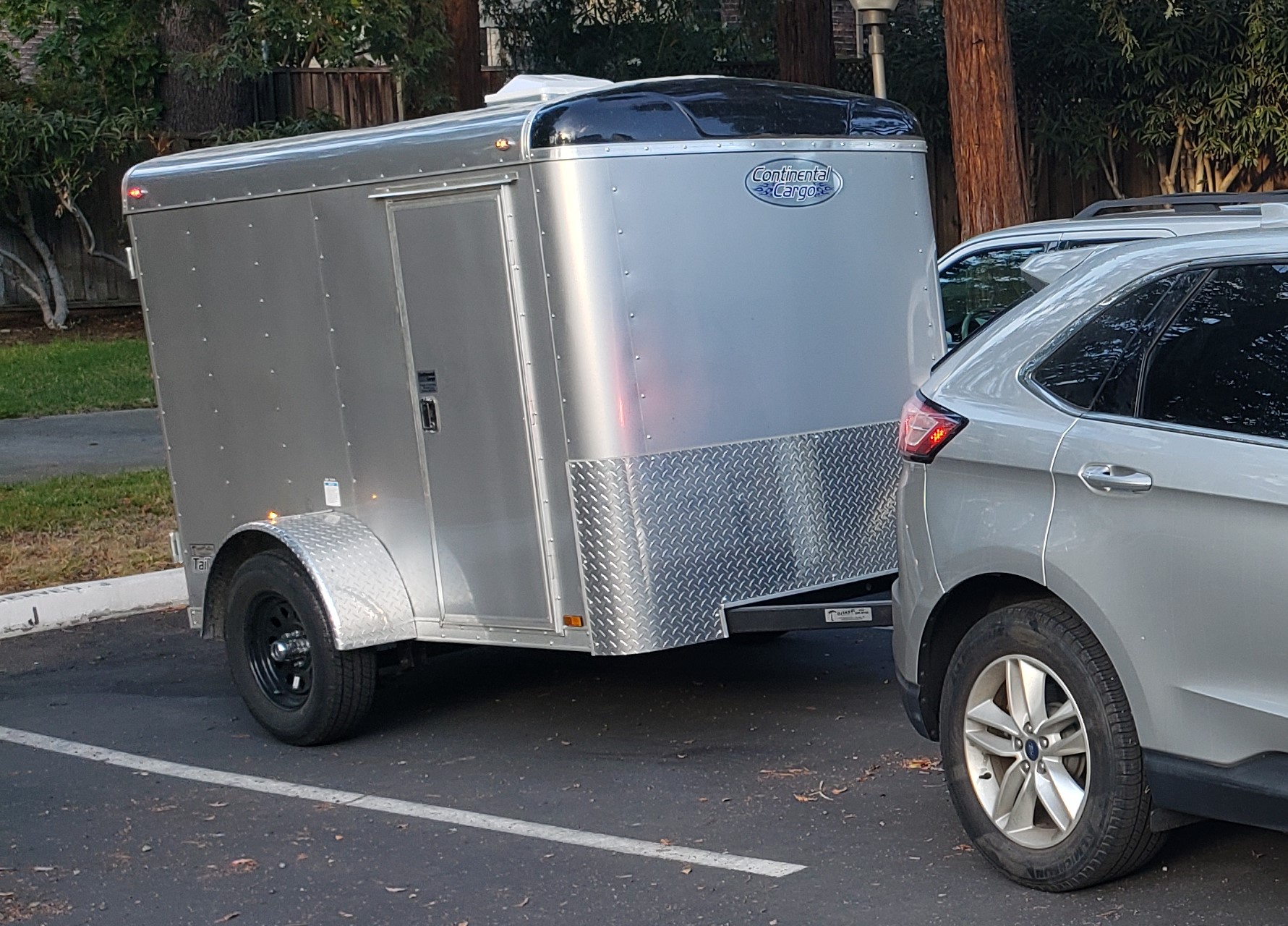
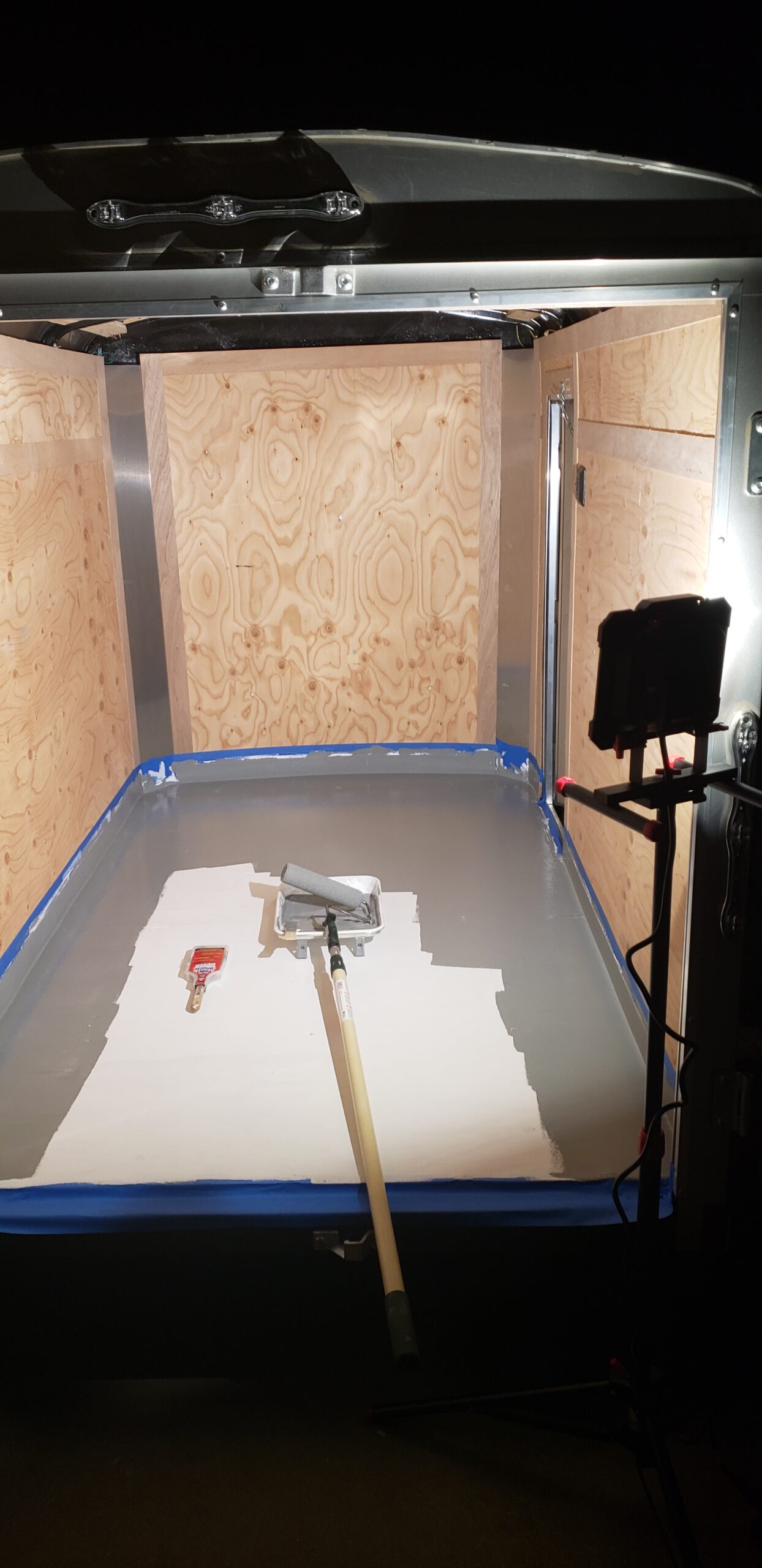
With an approved application, we jumped into the process of acquiring equipment, figuring out branding, building our menu, booking time in a commissary kitchen, and iterating / practicing our recipes. We purchased a used cargo trailer for transporting equipment,
As a dry run for our first farmers’ market, we catered a college student event for free (they paid for the ingredients, and we cooked everything and served it), which was hugely helpful for pointing out many flaws in our process; our prep/setup/everything time was way too slow, our menu was too big, and our recipes weren’t scaling consistently. Fortunately, college students like free food, and didn’t complain–but we knew we would need to step things up before setting up shop at a farmers’ market with real paying customers.
Problems identified during dry run:
- Low efficiency
- We spent probably 20 hours preparing, catering, and cleaning for an event where we served ~70 people. Definitely not scalable, but a lot of time was wasted in figuring out how equipment worked, loading equipment into separate cars (instead of a single trailer), and generally being extremely slow about everything.
- Our roles in the tent weren’t well rehearsed, and we kept tripping over each other and wasting a lot of time being blocked by each others’ tasks.
- We were missing some key equipment for improving our efficiency. For instance, we were julienning onions by hand (badly), when we could be saving a bunch of time by using an inexpensive manual machine to do the same task.
- Unscalable recipes
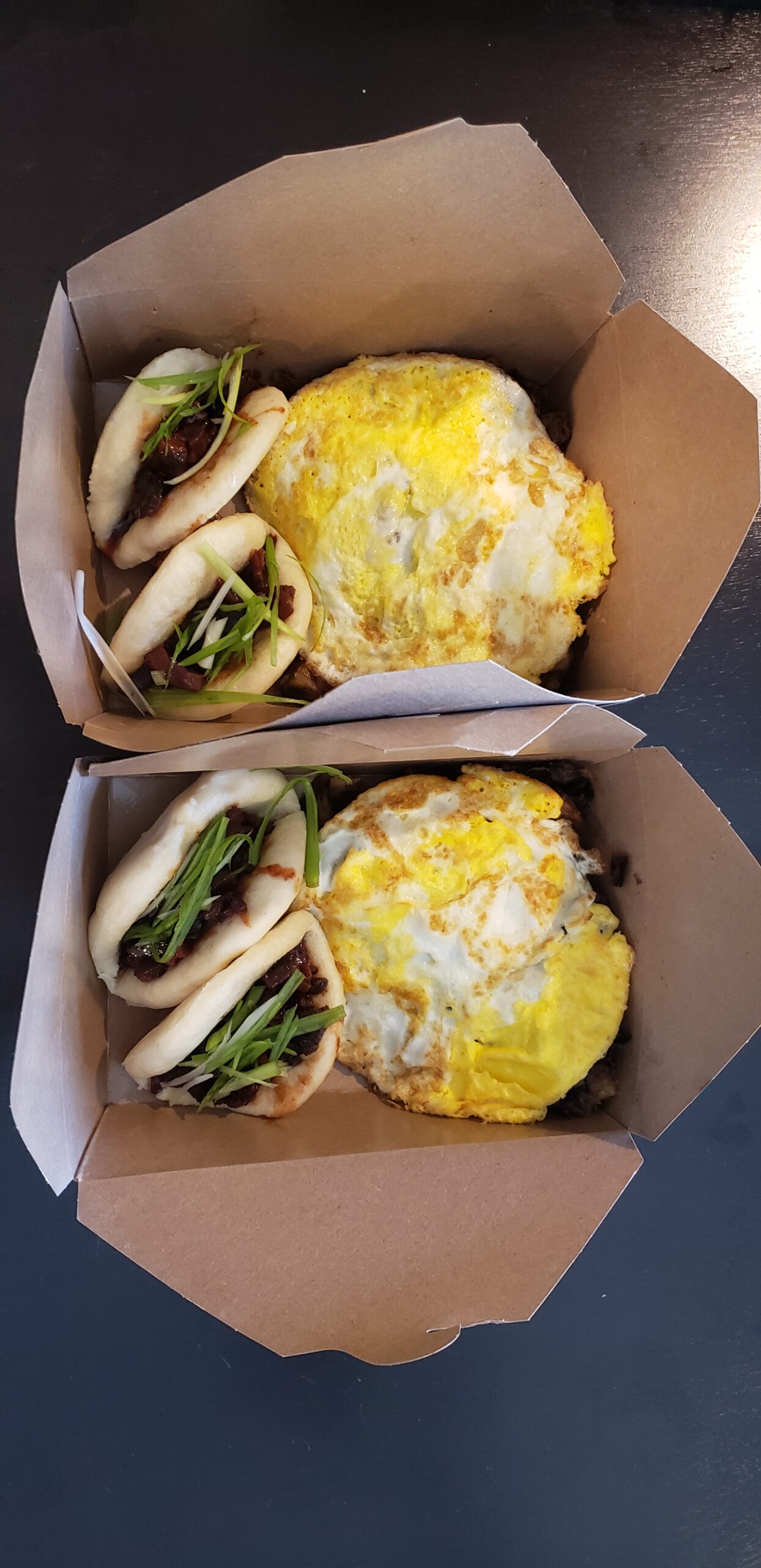
- One of the main pain points of the catering event was homemade bao buns, which we were making from scratch and steaming ourselves. These buns took a tremendous amount of time to hand-craft for us (as culinary noobs), and worse, were easy to over-steam and had very little durability for hot-holding. If one of our bao buns was overcooked or hot-held for too long, it would end up looking like a wet version of Emperor Palpatine’s face, and would stick to every available surface inside the steamer. Not good.
- We had a stir-fried eggplant dish that was 1) extremely slow to cook and 2) not that good. We needed to find a better way to cater to vegetarians.
- Dumb mistakes
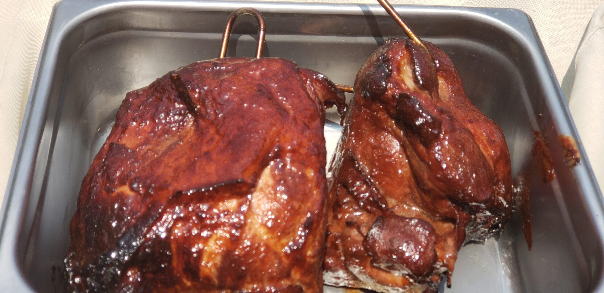
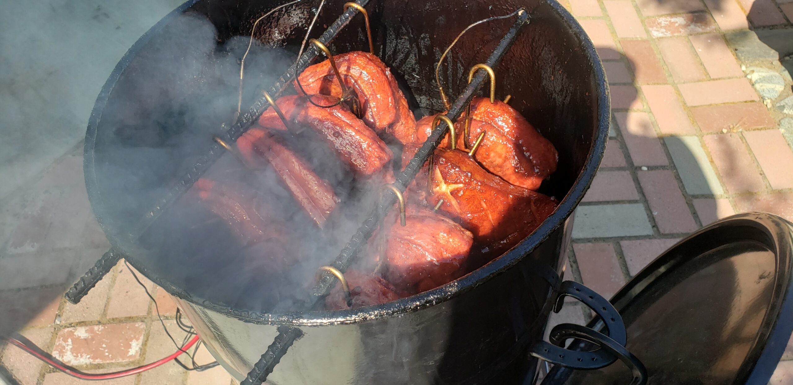
- We made some small mistakes that added up to become large issues. Most of these were related to missing items that we all assumed someone else had remembered to pack for the event. For instance, we forgot to bring honey with us to add to the char-siu pork belly burnt ends glaze, which meant we weren’t glazing the pork belly burnt ends in a delicious sugar crust, but rather frying them in some kind of pink pork oil/water mixture. Still tasty, but not nearly as good as what we had prototyped.
Happy takeaways from dry run:
- Our food was edible
- People seemed to like what we were serving, and thought it was very unique (in a good way).
- Operations had vast potential for efficiency improvements
- Most of our issues were related to a few small bottlenecks, and a lot of our production capacity was being wasted. This was great news! If we could eliminate some of these bottlenecks and streamline other parts of our operations, it was obvious that we could greatly improve our overall eficiency.
- This could work
- Running a farmers’ market hot food stand is going to be a LOT of work.
- Cooking for a large number of people on a tight schedule is fun, but in a stressful / kinda terrifying way.
Chapter 4: The Real Deal
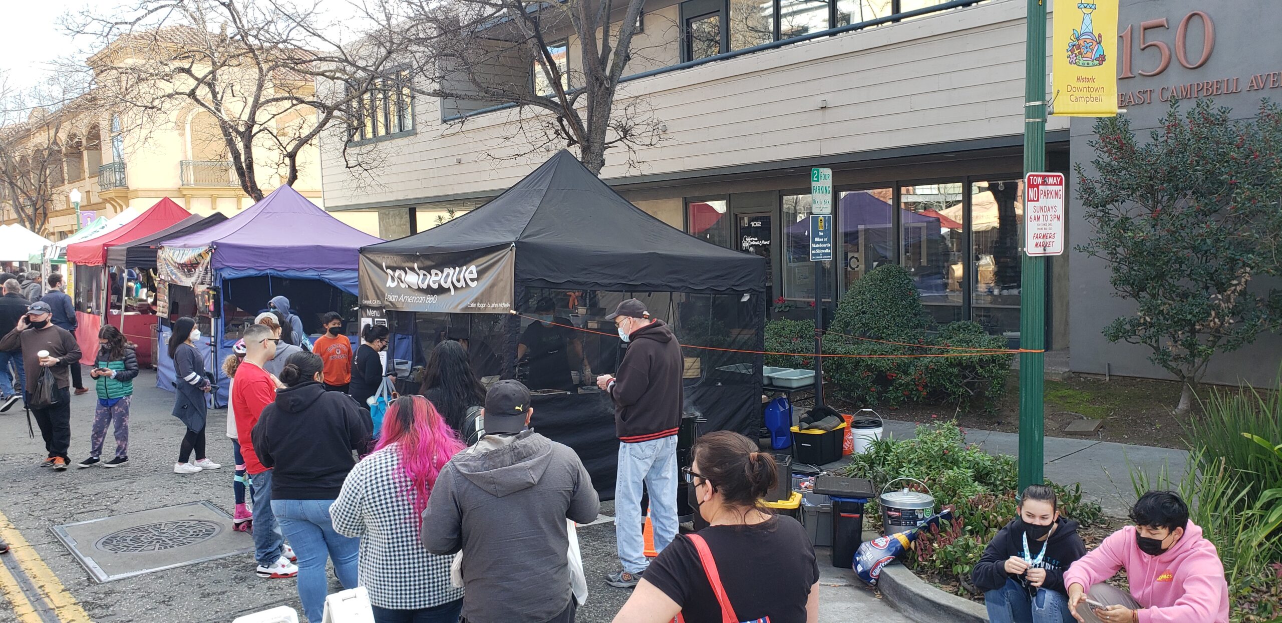
Baobeque’s first farmers’ market appearance was in early October of 2021.
Core memories from The First Market:
- We lucked out and happened to debut during the stormiest market of the year. It started dumping rain around an hour after the market opened, and not the light drizzle kind–the raining-horizontally kind.
- As total noobs, we figured everyone weighs down their tent with sandbags at the market, since that seems like a tenty thing to do. It turns out that sandbags are heavy and usually not needed at all, so nobody had sandbags on their tent except for us. Due to the aforementioned wind situation, we watched from inside our tent as other tents were blown over our heads and down the street during the market. I distinctly remember seeing an Indian food tent being blown about 20ft above the street with a propane tank still attached. There wasn’t much food selling happening at this point as everyone was focused on holding things down, trying to keep stuff dry, and helping people dodge flying tents / pick up the mangled pieces.
- Someone placed a cash tip into our open container of green onions, which was unfortunately located near the pickup window. Oops.
- Our total take from the first market was around $600. Impressive for a super rainy day, but not nearly enough to break even. Still, a great start!
- Some very kind friends stopped by to help us clean up after the market. Their help loading up our trailer in the pouring rain felt like a saving grace after a long day of prep / setup / cooking and getting soaked.
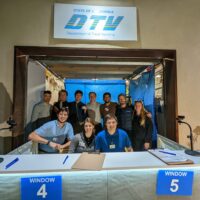
Sometime in our first few markets, a local student named Derek came and asked to film a food review. We were happy to say yes, and his well-produced video is still probably the best-documented video snippet we have of the customer experience. Of course, we were still getting our food ironed out, and a lot of the food presented in the video wasn’t yet our best work, but we were very happy to get a shoutout on the internet!
It was clear that we were bringing something unique to the farmers’ market, and customers seemed to really enjoy the dishes we were making. After our initial market debut, we continued to improve our operations and menu. Some improvements that we made:
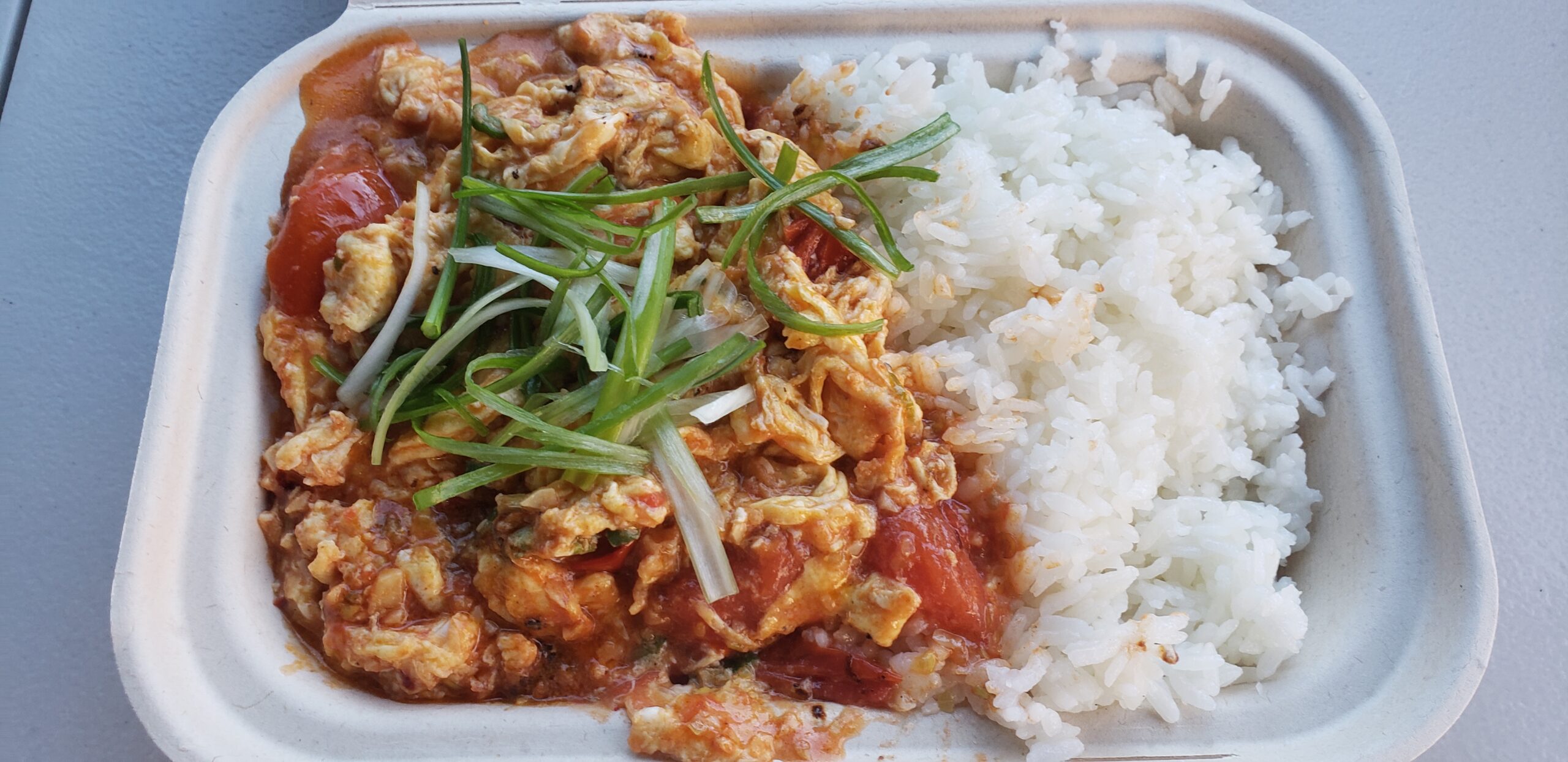
- Added a stir-fried Tomato-Egg dish as a vegetarian option. Probably our personal favorite dish but never got very popular among customers, for some reason.
- Wrote full checklists and written recipes for ingredient shopping, prep, setup, and teardown.
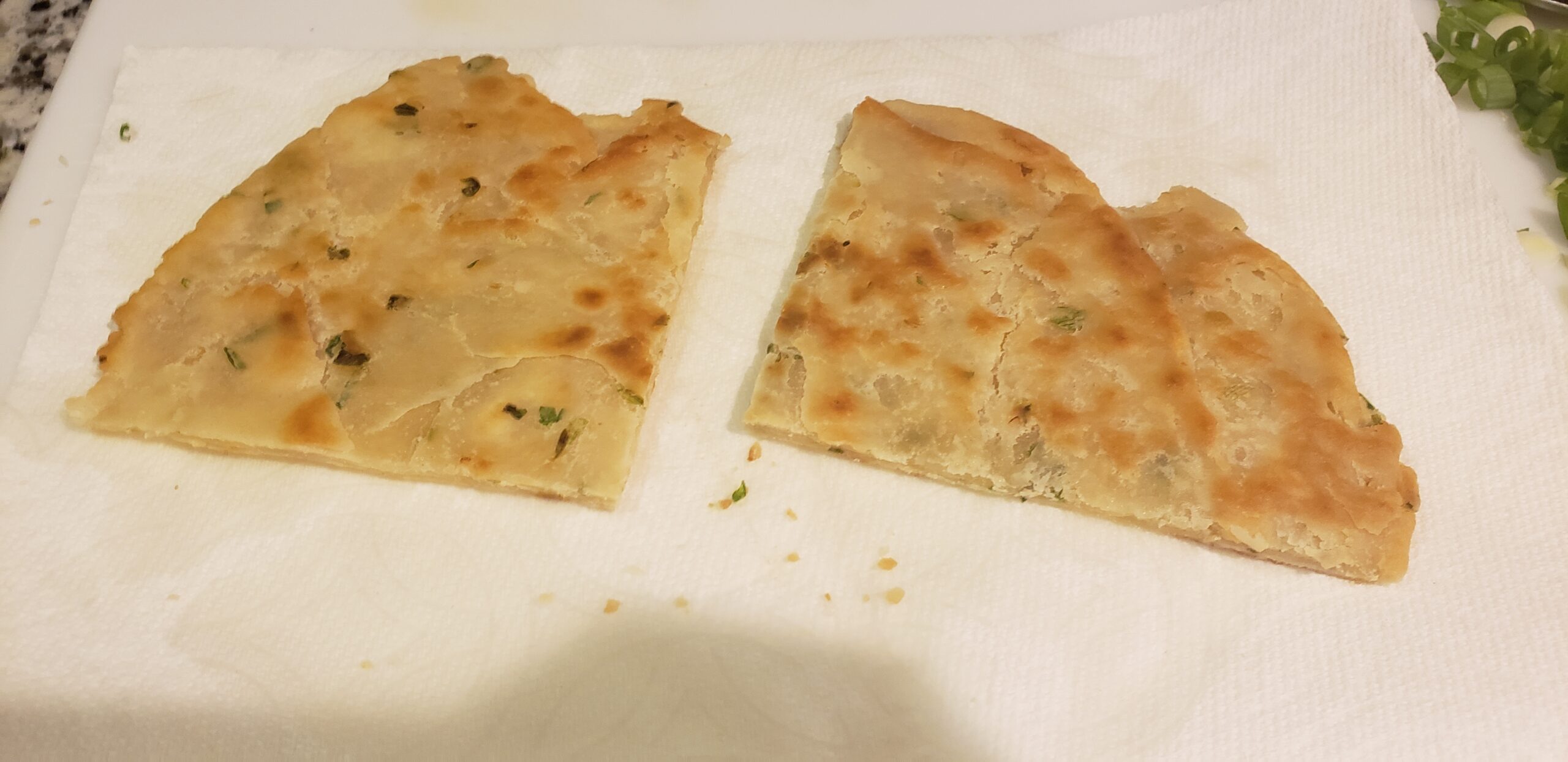
- Bought a $700 dough sheeter from Italy for improving our consistency and efficiency in preparing our custom green onion pancakes.
- Played around with some specials, including smoked beef back ribs.
- Cut out little blocks from 2×4’s and added some adhesive-backed sandpaper to make levelling blocks for our tables (the street was quite sloped where our tent was set up, and everything kept sliding to the back of the tent).
- Worked out a really efficient system for writing down orders (written shorthand), calling orders within the tent (verbal shorthand / keywords for acknowledging with a callback), and staging orders for minimum wait times (FIFO with early warnings for any potentially blocking shortages).
- Caitlin got really good at estimating wait times from the backlog, and usually was able to provide every customer with a wait time estimate that was accurate within a few minutes. She would write the time that the order was taken at the top of every new ticket, and this would be used for estimating current wait times. If an order was taking longer than the estimated time, everyone in the tent would know about it, and an apology could be made to the waiting customer (usually with a free drink or something similar).
- Kenneth became a bao assembling machine. Most weekends he would assemble 300+ bao for customer orders.
As we gained a following, and as the market began to get busier (due to the return from COVID and adding new vendors), we saw our sales steadily increase until we were in the range of $1400 to $1700 per market. This was enough to break even with ingredients, rent for the commissary kitchen, market fees, and salary (Caitlin and I were working for free). Seeing the same customers come back weekend after weekend was very rewarding, and assauged my fears that we wouldn’t be able to build a steady business.
Chapter 5: Can we make this a Real Business™?
Business was good, but running a farmers’ market stand on top of having full-time engineering jobs was beginning to take a toll. In addition to working 45+ hour weeks at our full-time jobs, we were working an additional 20-ish hours each every weekend to run the stand. The types of work were quite different, which could be refreshing, but the volume of work was getting to be exhausting.
The business was breaking even, but was not in a sustainable place. From the capital side, our numbers were barely working, since we were only operating one farmers’ market, so all of our fixed costs (commissary rent, equipment cost, business fees, etc) were only being amortized across a single day per week of business operation. From the labor side, our business had no redundancy and relied on all three of its employees working at 100% capacity at all times, since any single person calling out sick for even just a few hours of work on a weekend could shut down the whole operation. We were faced with a decision: ride the burnout train into the ground, or put in one more big huff of effort to try professionalizing and expanding the business to a point where it could survive without continued unsustainable effort from our side. As optimists, we chose the second path, and set about making a Real Business™.
For Baobeque to survive without our own continued effort, we realized that it would need to become a self-sustaining business with its own employees and management. We were already doing things above board (paying all relevant permits and sales tax, great documentation for our processes, etc), which was a great starting point. In order to hire Real Employees™ for our Real Business™, we needed to write up an employment contract and employee handbook, figure out a payroll system, pay for employee insurance (in case of injury on the job), and collect (withhold) income tax from employee wages. This turned out to be substantial effort, but with the help of some of the readily available digital tools for small businesses (Square is a lifesaver), the process was completed within a few weeks. So, we put up a “hiring” sign, set the hourly wage as high as we could possibly afford ($18/hr), and waited for someone to ask us about it!
Within a few weeks, we lucked out and were contacted by someone who was the become our first Real Employee™. He had a great attitude and were quick to learn the ropes. Our original intention was to have him come to the market and learn the process for a while, and then have Kenneth take some weekends off. However, hiring our employee corresponded with an increase in sales, and any slack that was left was taken up by new processes we had to introduce to be compliant with labor laws (e.g. minimizing overtime work, mandatory bathroom and meal breaks, etc). We hadn’t had to stick to these processes previously since the only people working in the booth before weren’t paid employees. Adding these provisions increased the cost of doing business, but were obviously necessary. We hadn’t realized how much we’d been burning the candle from both ends just to make things work! And at the end of the day, if a job needs to not allow bathroom breaks to be financially viable, that job is either vastly under-valued or probably isn’t worth doing in the first place.
In order to pay for our higher costs that resulted from converting to a Real Business™, we raised our prices to the highest level that we thought would be fair to our customers (we gave our regulars some discounts during the cost increase period to soften the blow). Due to a number of factors, our revenue increased slightly and reached a more-or-less sustainable threshold. We were cash-flow positive as a Real Business™, but only by a hair. And, we didn’t have enough revenue to pay supervisors or owners more than the base employee wages, which would make promotions difficult.
Some things influencing our profits during the Real Business™ transition:
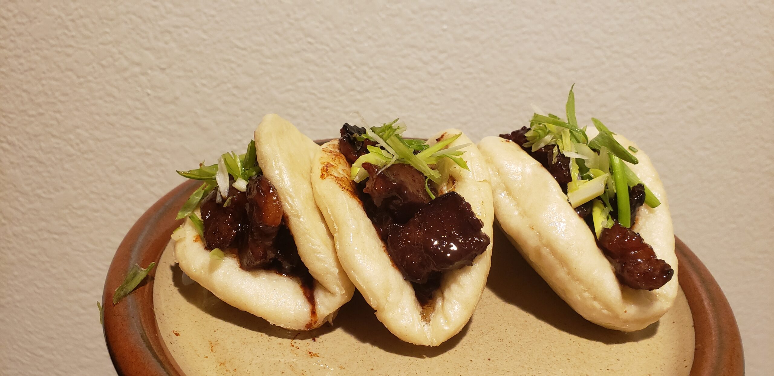
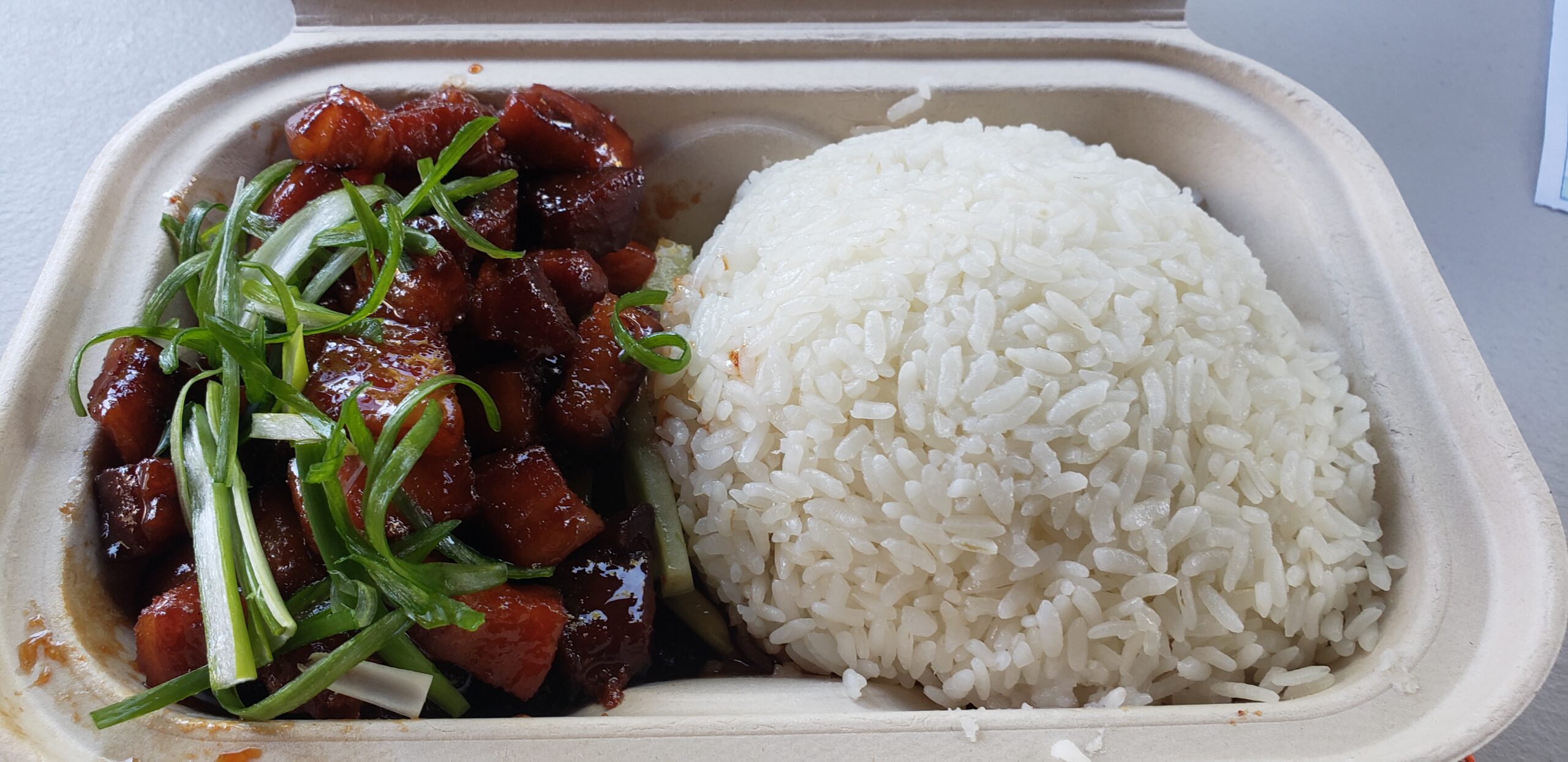
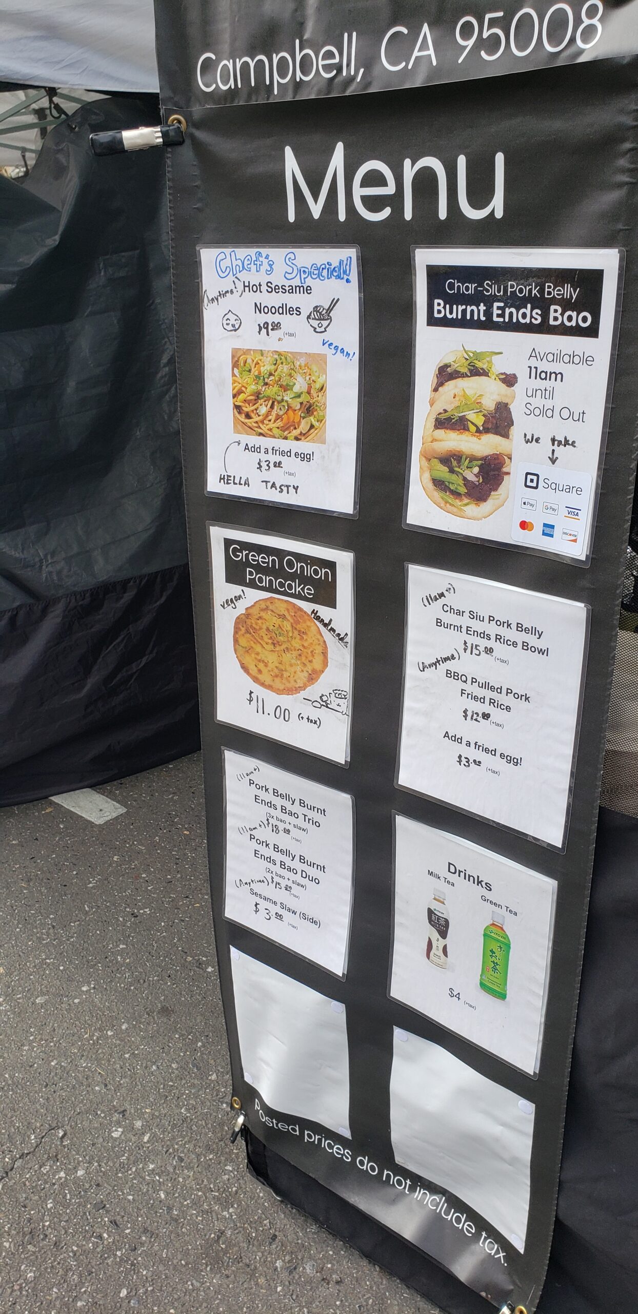
- (+ revenue ) We raised our prices. For instance, a 3-bao meal with a salad went from its original price of ~$10 when we first opened up to a final price of $18! We tried to keep some “deep value” items on our menu with large portions and low costs to keep hungry customers satisfied (we sold jam-packed containers of slow-smoked pulled pork fried rice for just $12, usually enough to feed two people).
- (- revenue) A really tasty dim-sum tent opened next to our booth in the market, which reduced demand for our product slightly by helping fill out the Asian food niche (but also resulted in some excellent food trades where we got to go home with some delicious shu mai and har gow).
- (- profit) Pork prices went way up, something like 30%.
- (+ revenue) Farmers’ market foot traffic increased as summer approached.
- (+revenue) We introduced a new vegetarian dish to replace our less-popular tomato egg. We began serving hot sesame noodles, a spin on the Wuhanese dish Re Gan Mian, but with slightly different ingredients. This dish was easy to make in volume and had great profit margins.
Having completed our Real Business™ transition, with two employees (Kenneth converted to a full time employee during the transition), two co-owners, and a fully insured and above-board business, we had a toehold on a sustainable business plan, but residual burnout was creeping back in. Caitlin and I wanted some time on the weekends back, and Kenneth was about to start a new full-time job. At work, I was getting promoted to a management position on top of my existing engineering responsibilities, and I knew that I would need to find a way to not do 20 hours of farmers’ market work every weekend (along with additional hours of miscellaneous tasks outside of work hours during the week) in order to maintain my sanity and put my best food forward at work. We would need to find a way for the business to operate without us involved in day-to-day operations if it was going to be sustainable long term.
Chapter 6: The Impossible Chicken Egg Problem
To make the business run truly hands-off, we would need to hire someone who could be an experienced supervisor, and train them to train more people. To pay for an experienced supervisor, we would need to join more farmers’ markets to increase our revenue, better amortize our operating costs, and increase our economies of scale. But, since we already had full time jobs and were operating at 100% capacity, we had no bandwidth to join additional markets, or even really start a hiring search for a supervisor or new employees in earnest. If we wanted to expand the business to a sustainable and scalable point, we would need to invest a substantial amount more resources, into the business in the short term both in capital and in our own time.
Caitlin and I are both very passionate about our jobs (we’re engineering nerds and getting paid to build stuff with technology is actually the best), and neither of us was down to leave our engineering career to work on the farmers’ market business. We spent some brief time searching for a buyer, but didn’t find any initial takers and weren’t willing to run the business indefinitely while searching for someone to hand it off to. Our employee expressed some interest in acquiring the business, and we were excited about the prospect of selling it to him (at a very good price), but ultimately he wasn’t able to secure the funding and support he would need to run it sustainably. In the end, we made the decision to close the business as gracefully as possible while taking care of our employees, friends, and customers as best we could.
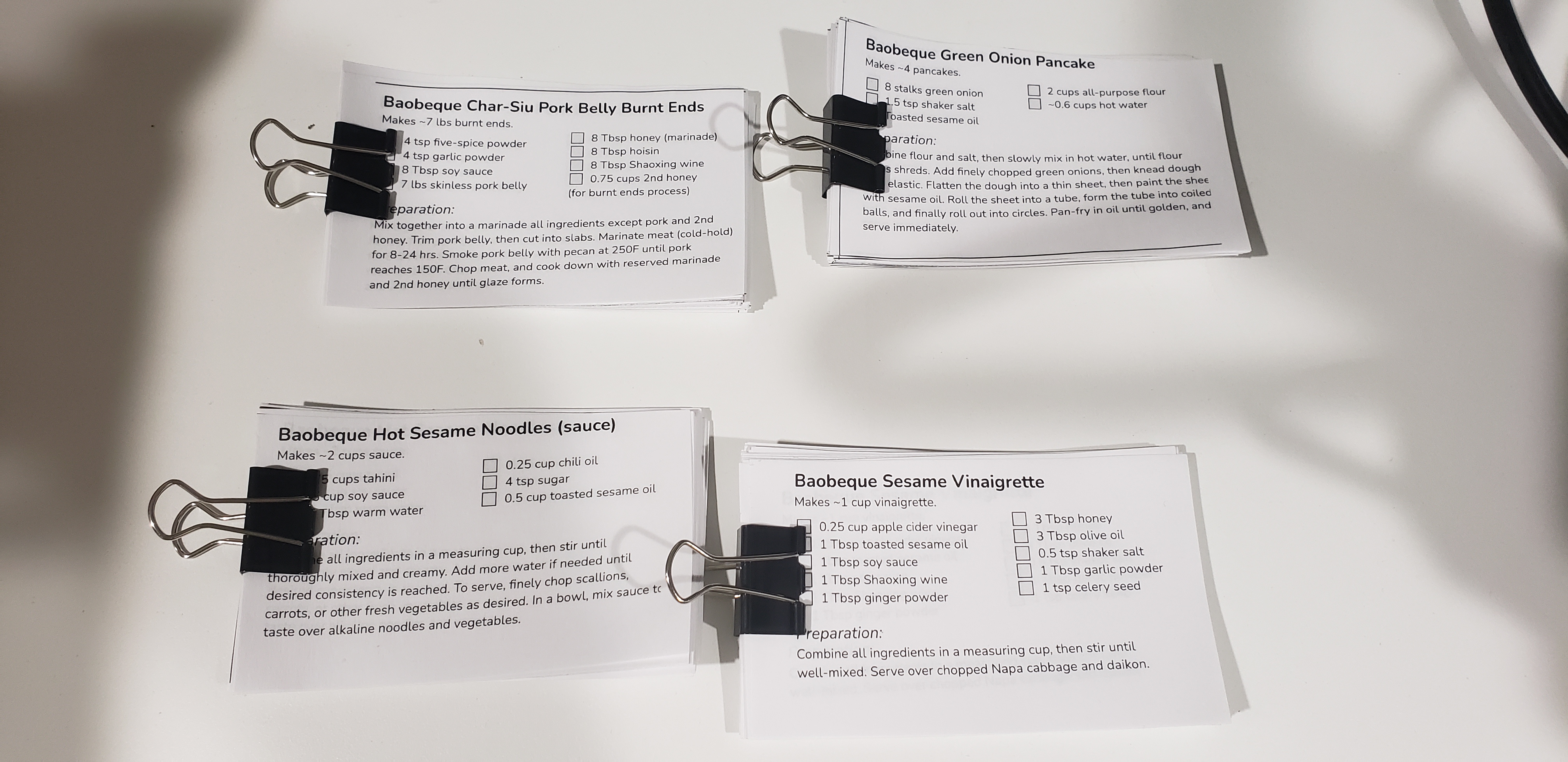
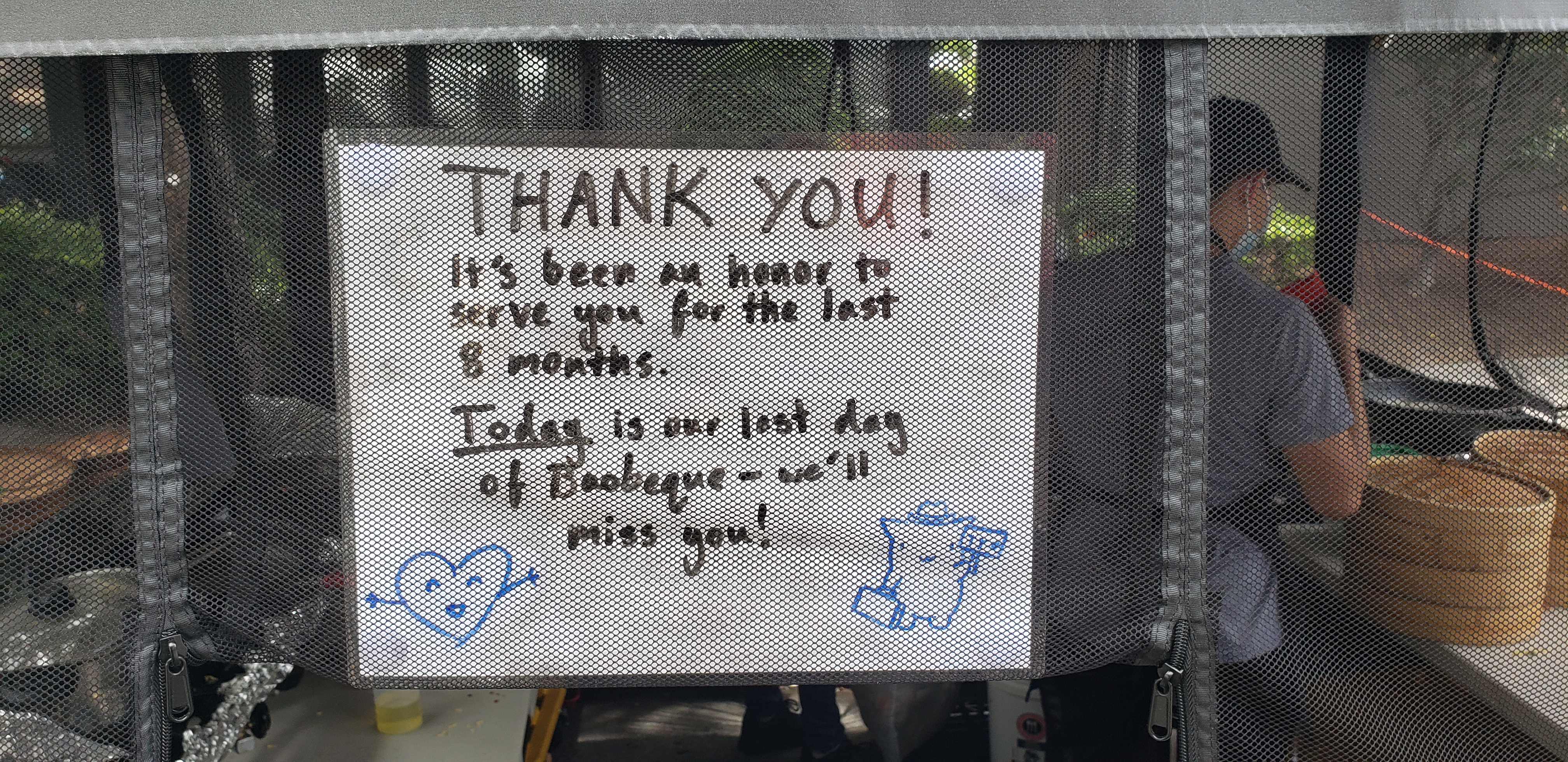
Baobeque’s last day of operation was on June 12th, 2022. We notified our customers in the weeks leading up to our closure, and many of our regulars came by to place one last order (or many last orders). We also printed up recipe cards for our most popular dishes, and handed them out to anyone who wanted them, so that anyone who had grown to love the taste of our food could try replicating it themselves.
While closing the business, we gifted our employees a generous severance package, and began selling off our major pieces of equipment piece by piece. Many of the friends we had made at the farmers’ market and the commissary kitchen were more than happy to buy our used equipment, and we were happy to provide them great prices as a token of our friendship. On June 19th, 2022, the Baobeque crew enjoyed a wonderful Sunday morning of sleeping in for the first time in a long time.