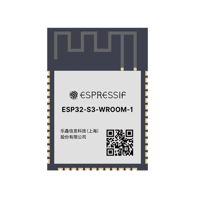
As part of running the ADSBee project, I’ve found myself with the less than exciting job of counting tens of thousands of components for inventory and consignment purposes, ranging from tiny 0201 resistors and caps to large LGA modules like the ESP32 S3.
Usually, counting these components is done by figuring out the pitch of the tape (number of components per 4mm feeder hole), and then measuring out the length of the tape by hand using a ruler or yardstick. This is relativley quick for small cut tapes, but can quickly become untenable for partial reels of components, where it can be easy to lose track of the exact hole you last had at the end of the measuring tape if you need to measure multiple lengths at a time.
There are a number of existing solutions to this problem, which generally rely on some sort of device that counts the holes in the tap for you, and multiplies it by the part pitch to give you a component count. I had backed one of these devices, the BeanCounter, on CrowdSupply, but sadly my order never shipped (I think I placed it after the initial batch was sold, and no subsequent batches were ever made). After more than a year of waiting for my BeanCounter, and counting thousands of parts by hand, I got tired of waiting for a solution to appear and decided to put something together myself.
BeanCounter’s main draw was that it was a small and relatively portable device that could do the task of much larger desktop-mounted machines. It used a few photo gates to count holes on paper tape as it was pulled through, and had a very sleek dual PCB design with a counter display that was diffused through a layer of FR4. The whole thing runs on a coin cell battery, and is small and light enough to put in your pocket.
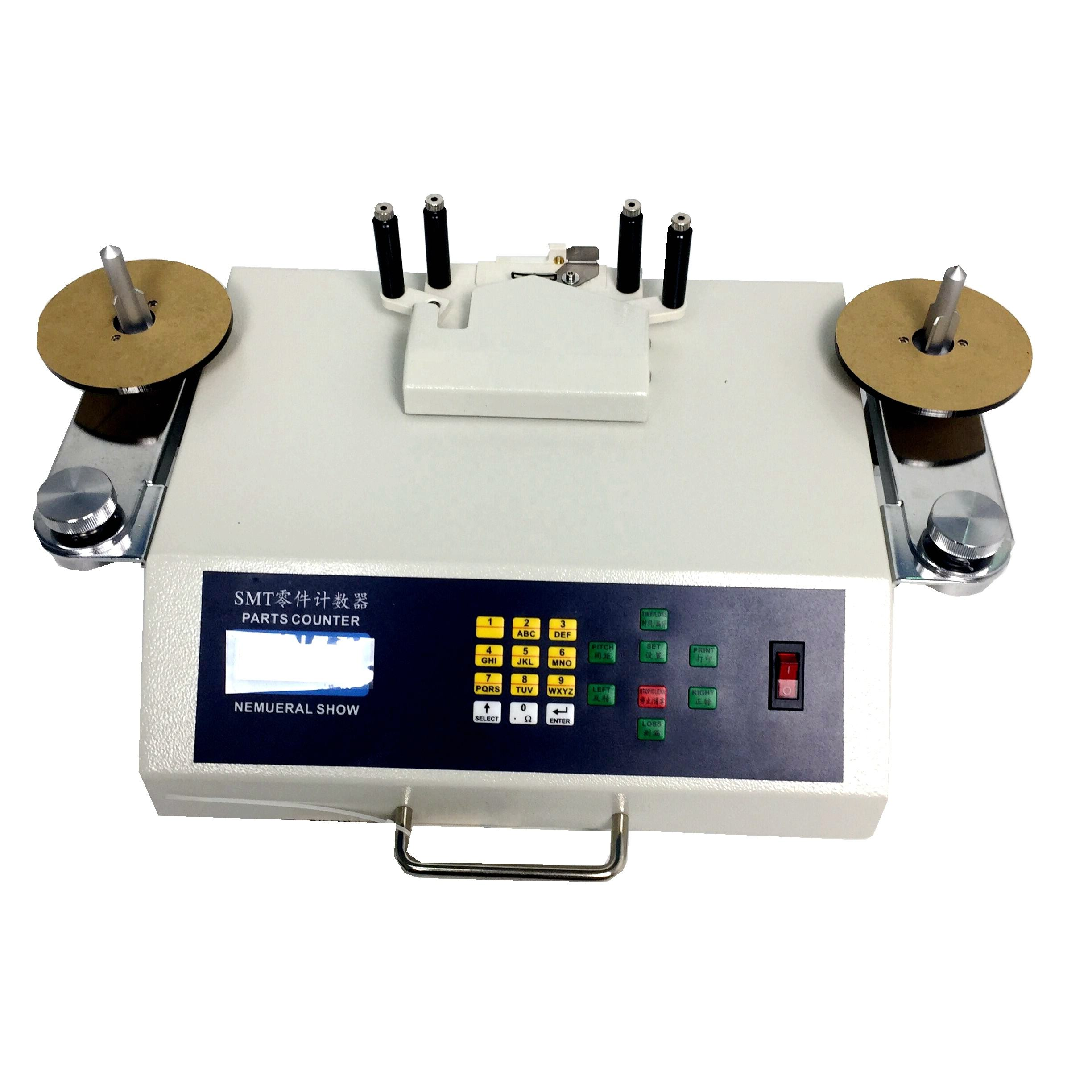
By comparison, the SMT counter machines used in factory applications are expensive and relatively heavy, and often have automatic spools that can drive the components between two reels while counting the holes as they go by. These cost hundreds of dollars each, and everyone knows that any benchtop shaped piece of real estate in my lab has already been completely claimed by expensive equipment or various piles of mission critical garbage. For an infrequently used tool like an SMT component counter, dedicating valuable benchtop real estate wasn’t in the cards. So, it was time to build something small (and cheap), with some of the features of BeanCounter, and some extensions that would make it better for my application.
There were a few key disadvantages to the BeanCounter, other than its lack of availability. The BeanCounter was optimized for 8mm wide paper tape, which can be pulled through the device manually. The slot in the device that captures the paper tape is only sized for 8mm wide tape, so wider tapes with other components I use (like ESP32 modules), or tape with deep pockets (for connectors or electrolytic capacitors) simply wouldn’t fit. I haven’t used a BeanCounter myself, but I also imagine that it might struggle with different tape types, like transparent plastic tape that is often used for larger ceramic capacitors (although those tapes might be too thick to fit through the tape slot anyhow). Any device that I built would need to accommodate all tape colors and material types (clear plastic / black plastic / paper), all tape widths (8mm to biiiiig), and all pocket depths. After some head scratching and a few days of impulsive CAD modeling, I came up with a workable solution!
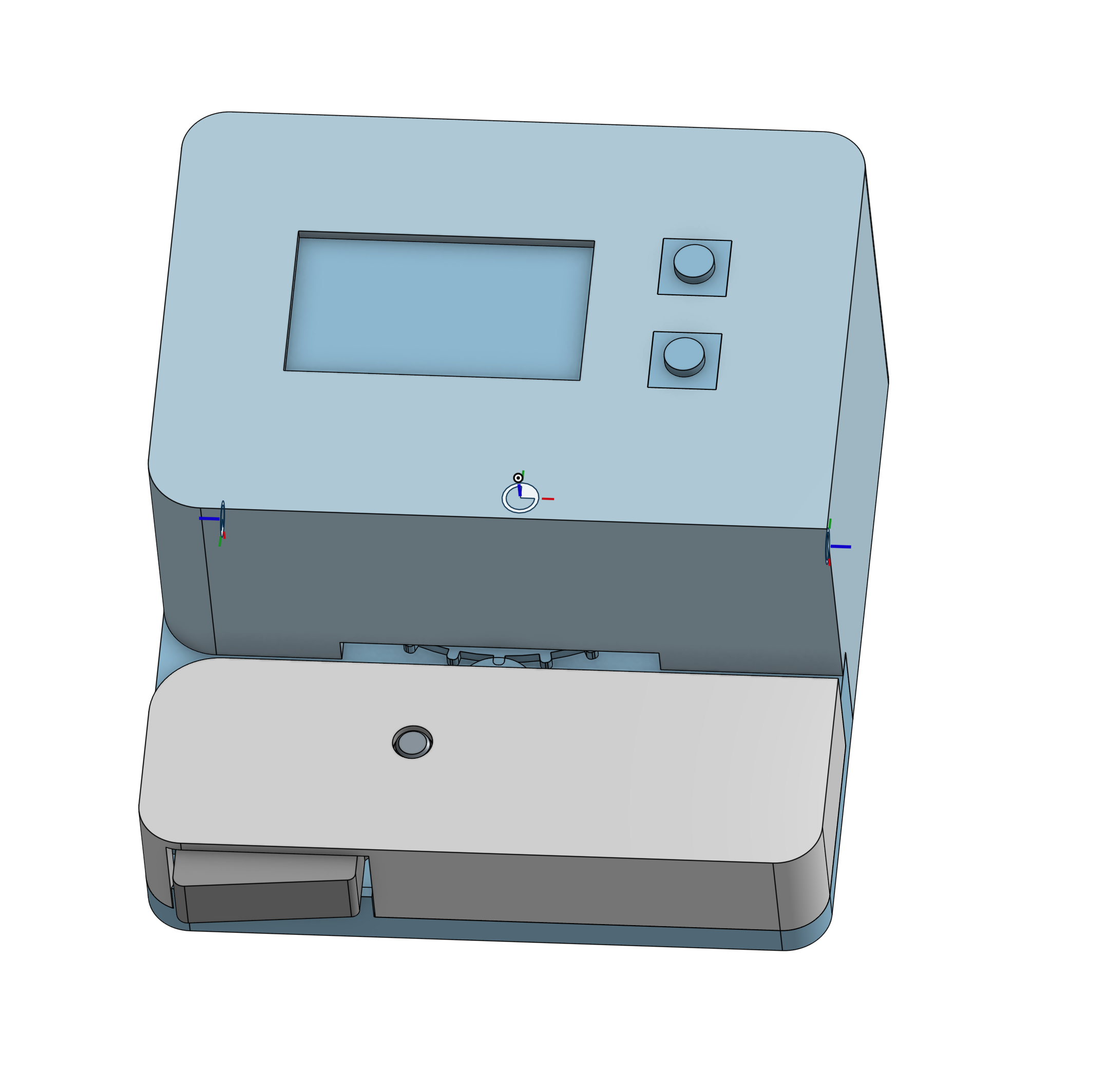
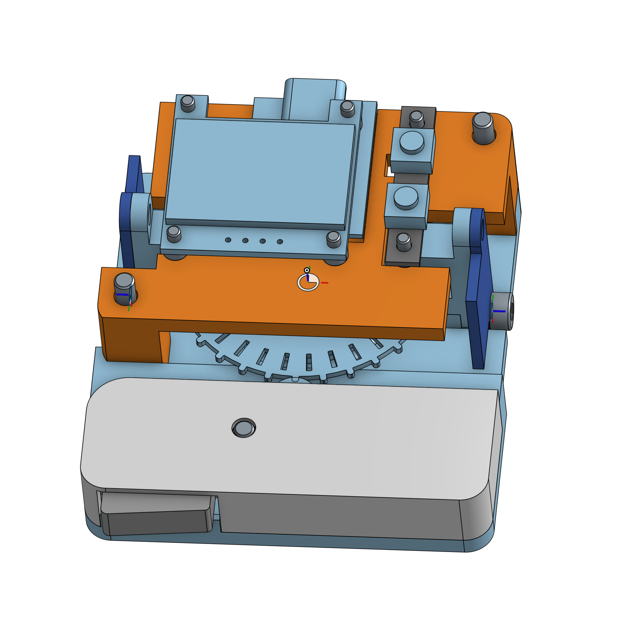
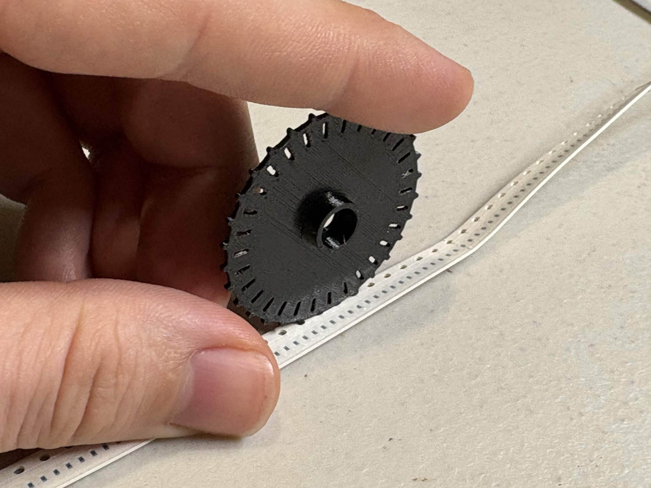
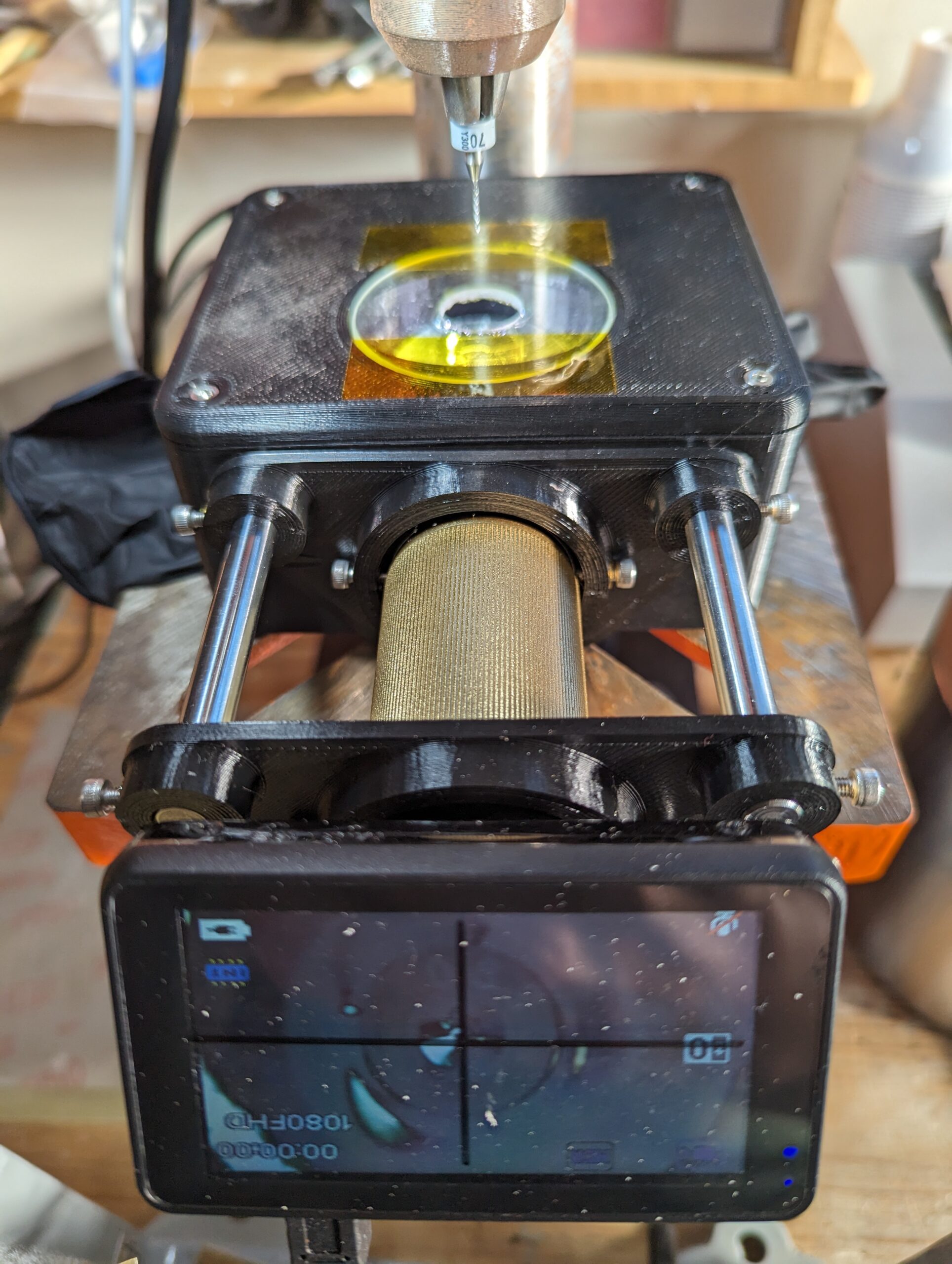
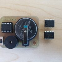
The Dotterboard uses a 3D printed sprocket wheel to engage with an SMT component tape and count the holes. Each hole grabs a single tooth on the sprocket wheel, which has a corresponding slot closer to the center of the wheel. Reading slots with photo gates inside the dotterboard allows the slots to be counted, and reading with two photo gates that are set 90 degrees out of phase (in quadrature) allows the direction of travel to be discerned as the slots are counted.
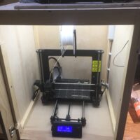
I was pleasantly surprised at how easy it was to 3D print a sprocket wheel to engage with the SMT tape holes. I swapped a 0.2mm nozzle onto my printer to get better resolution, and printed at a relatively low layer height with PETG.
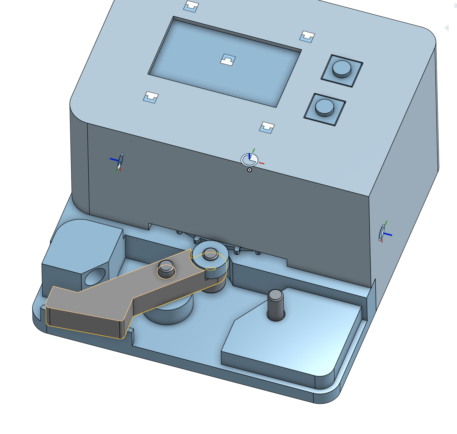
The sprocket wheel is held onto the component tape from the opposite side using a spring-loaded idler. The idler includes a release lever that can be used to disengage the sprocket wheel from the tape in the middle of a count, and the spring loaded bearing makes a very satisfying “takkatakkatakkatakka” sound as the SMT tape is pulled through the counter, providing a helpful auditory cue that the tape is properly engaged with the sprocket wheel.
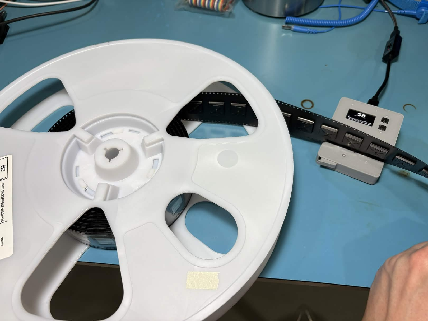
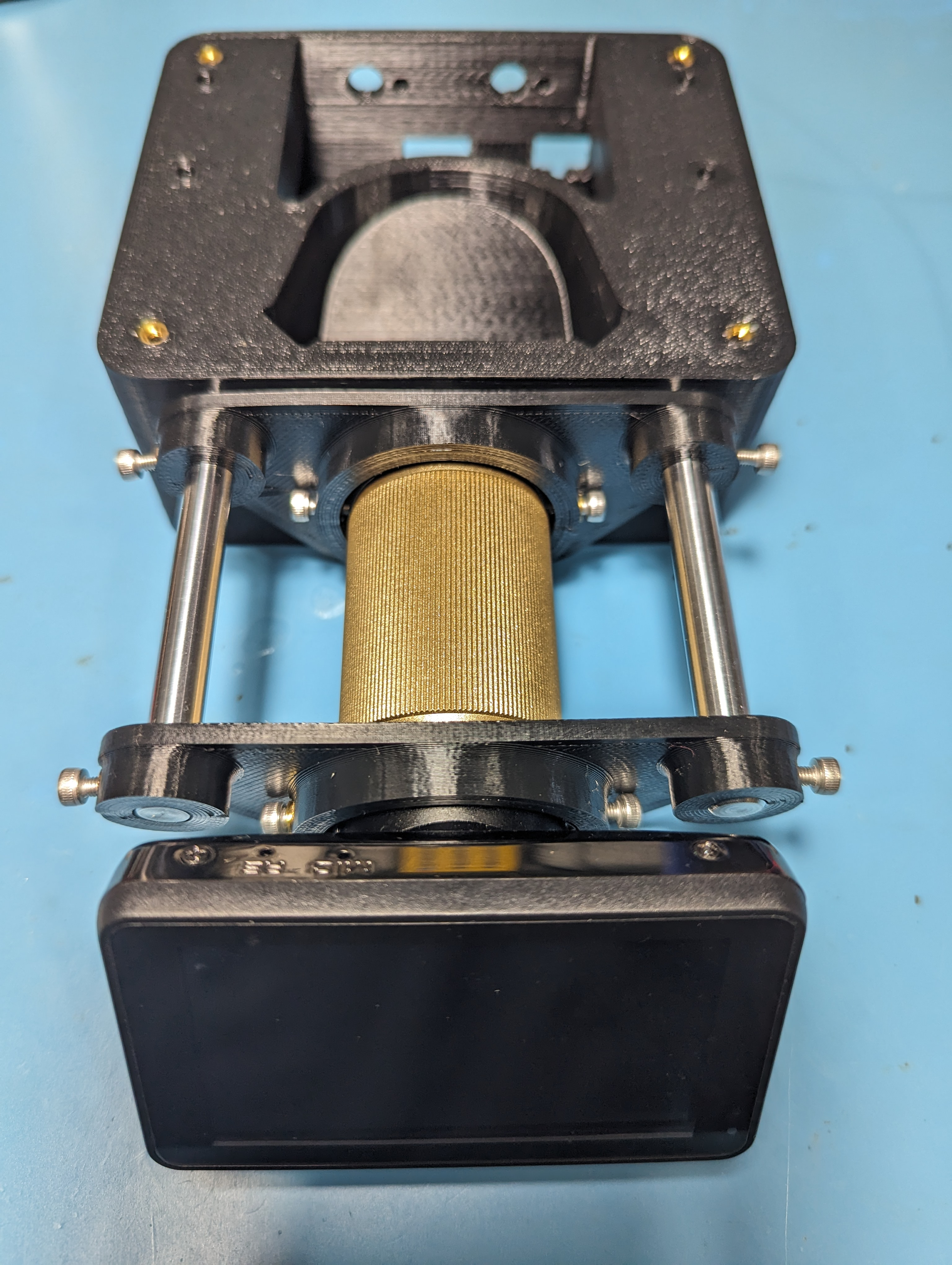
The enclosure section with the idler is designed to be intentionally low, so that componet tape with deep pockets can be counted without interfering with the enclosure of the Dotterboard. The fact that the 4mm pitch holes in the SMT tape are only engaged on one side means that the tape can effectively have unlimited width. This comes in very handy for measuring out extra wide component tapes like a partial reel of ESP32 modules.
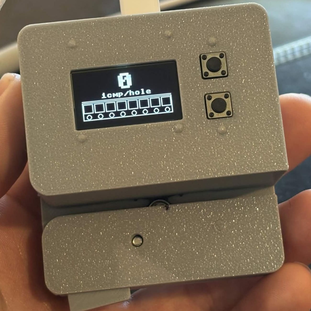
User input is provided via two buttons, and the component count as well as a graphic of the current programmed tape pitch are shown via an OLED display. I was very pleasantly surprised at how good Claude Code was at generating a simple GUI! The whole UI was generated in about 15 minutes of vibe coding, and the cute graphic that Claude generated for the SMT tape was actually quite a bit prettier and more intuitive than what I had been originally thinking of for a GUI design. The guts of the actual encoder program were another matter entirely; it took quite a long time to get a decent program for component counting that wouldn’t skip steps. My experience with AI coding seems to be that it either one-shots it on the first try, or might come up with a good fix on the second or third tries, but if it’s still broken after that, an AI agent can circle the drain for what seems like ages without coming up with anything that actually fixes the problem, while continuously adding unnecessarily complexity. After an embarassingly long time helping Claude use PIO and harrassing it about proper use of interrupts, I did manage to get the rest of the program working well, with no missed encoder counts at any tape speed (it seems like interrupts in MicroPython don’t like to interrupt I2C transactions, so the screen refreshing was causing encoder counts to be missed occasionally). While I do think that I may have had an easier time vibing this simple application in C++ (a better choice for something as real-time as a PIO + interrupt based encoder counter), the performance of the final product is still perfectly adequate when built with MicroPython.
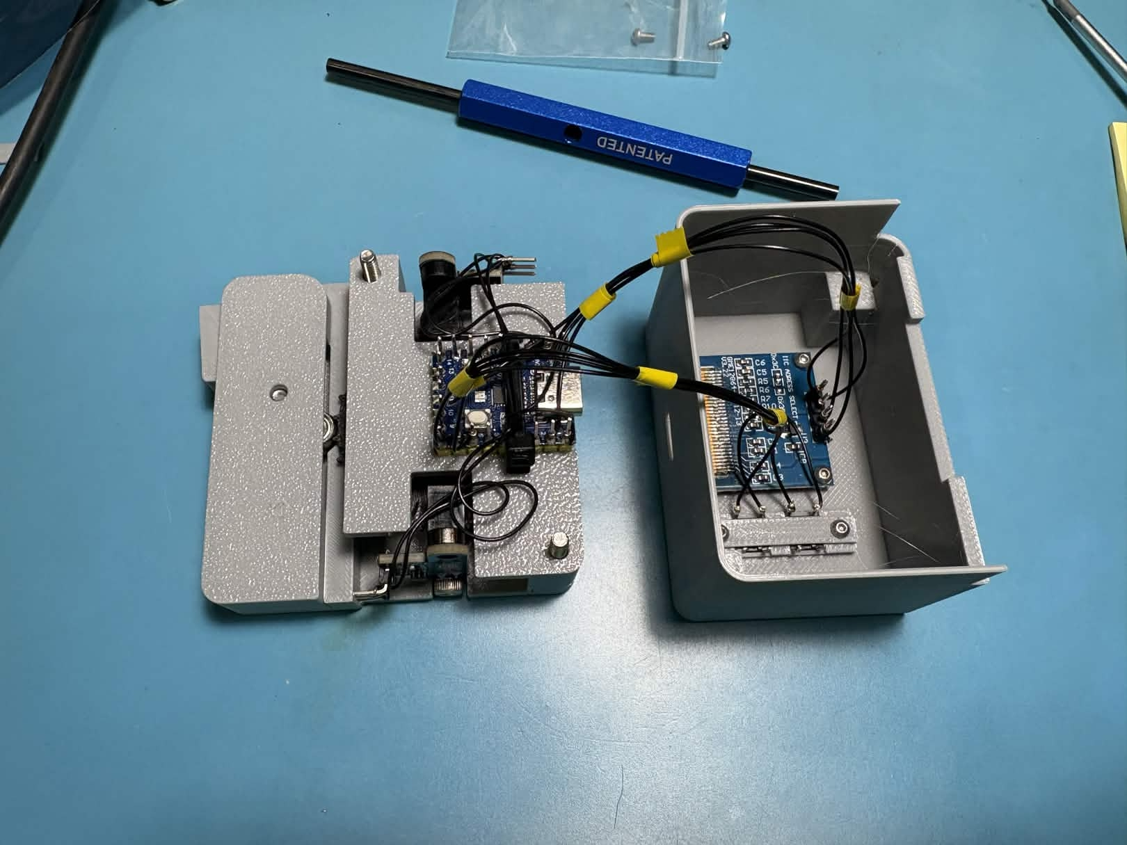
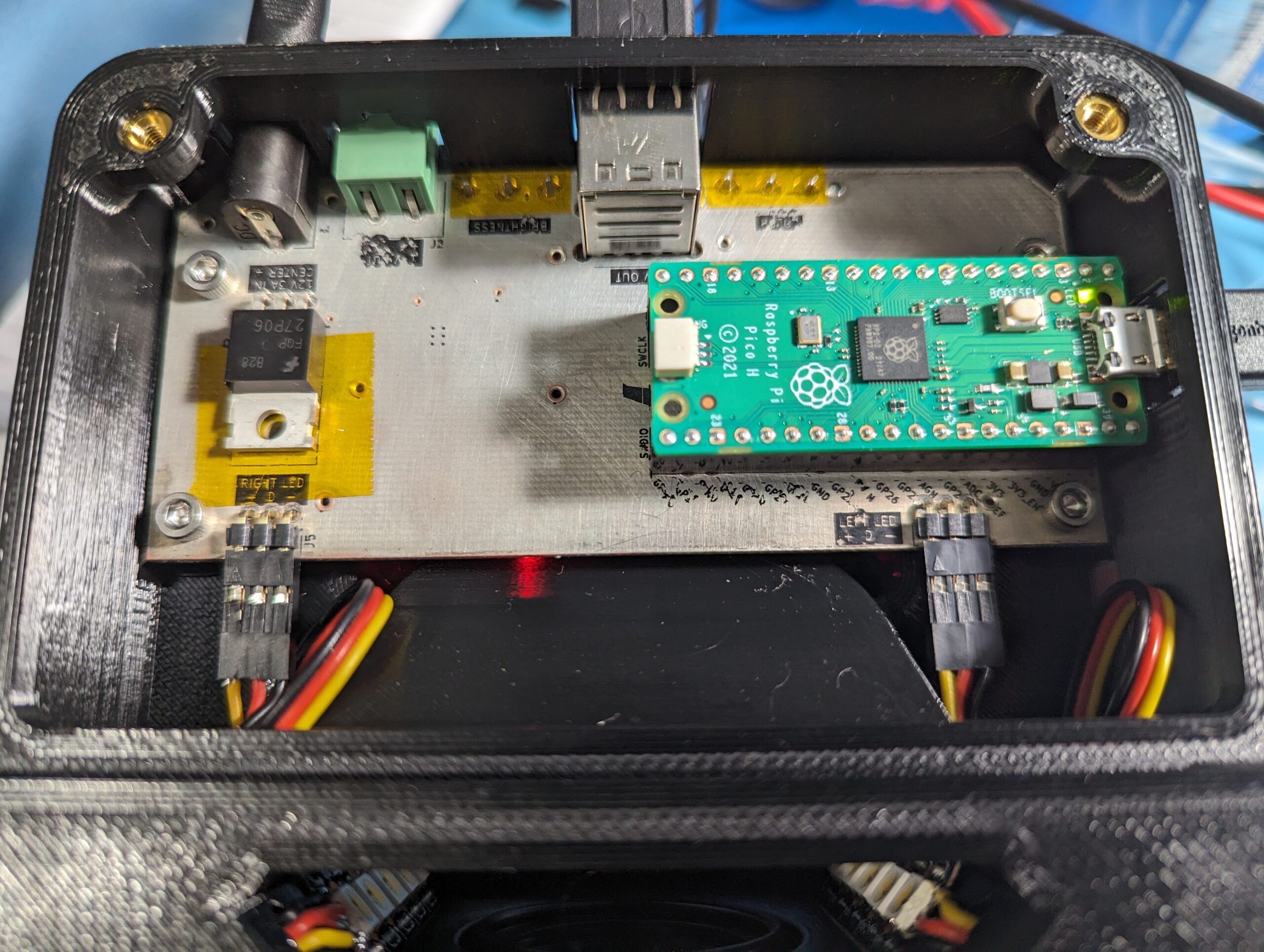
In an effort to avoid soldering a custom PCB for the Dotterboad, I decided to break out the wire wrap tools! I pushed the pin headers for an RP2040 zero module up through their plastic spacer strip until they formed decent wire wrapping posts, and proceeded to connect the two slot sensors, the OLED screen, and the two buttons with wire wrap wire. I made a fun little bench for the two through hole buttons mounted into the front of the case, and wire wrapped directly onto their legs in order to avoid building a front panel PCB.
Tada! That’s the whole thing. It plugs into USB C for power (although this could probably be extended to send data automatically to a computer if someone had an application for that). Pressing the top button increases the number of components per hole, pressing the bottom button decreases the number of component per hole, and pressing both buttons clears the part count. It’s capable of counting up and down (including negative numbers), and the little SMT tape graphic on the screen updates to reflect the number of components per hole (or the number of holes per component, for larger parts).
I’ve made the whole thing open source on GitHub in case anyone else wants to make one! It would be relatively easy to consoldiate the buttons, OLED, and RP2040 into a simple PCB, which would cut out all the cursed wire wrap hackery and also allow the case to shrink a little bit. If enough people are interested in building or buying one, I’d consider making one! Drop me a line at john[at]pantsforbirds.com if that sounds like something you might want.
If you do build one, I’d love to hear from you! This tool has already saved me quite a few hours of counting parts, so I hope that others might be able to get some use out of it as well.
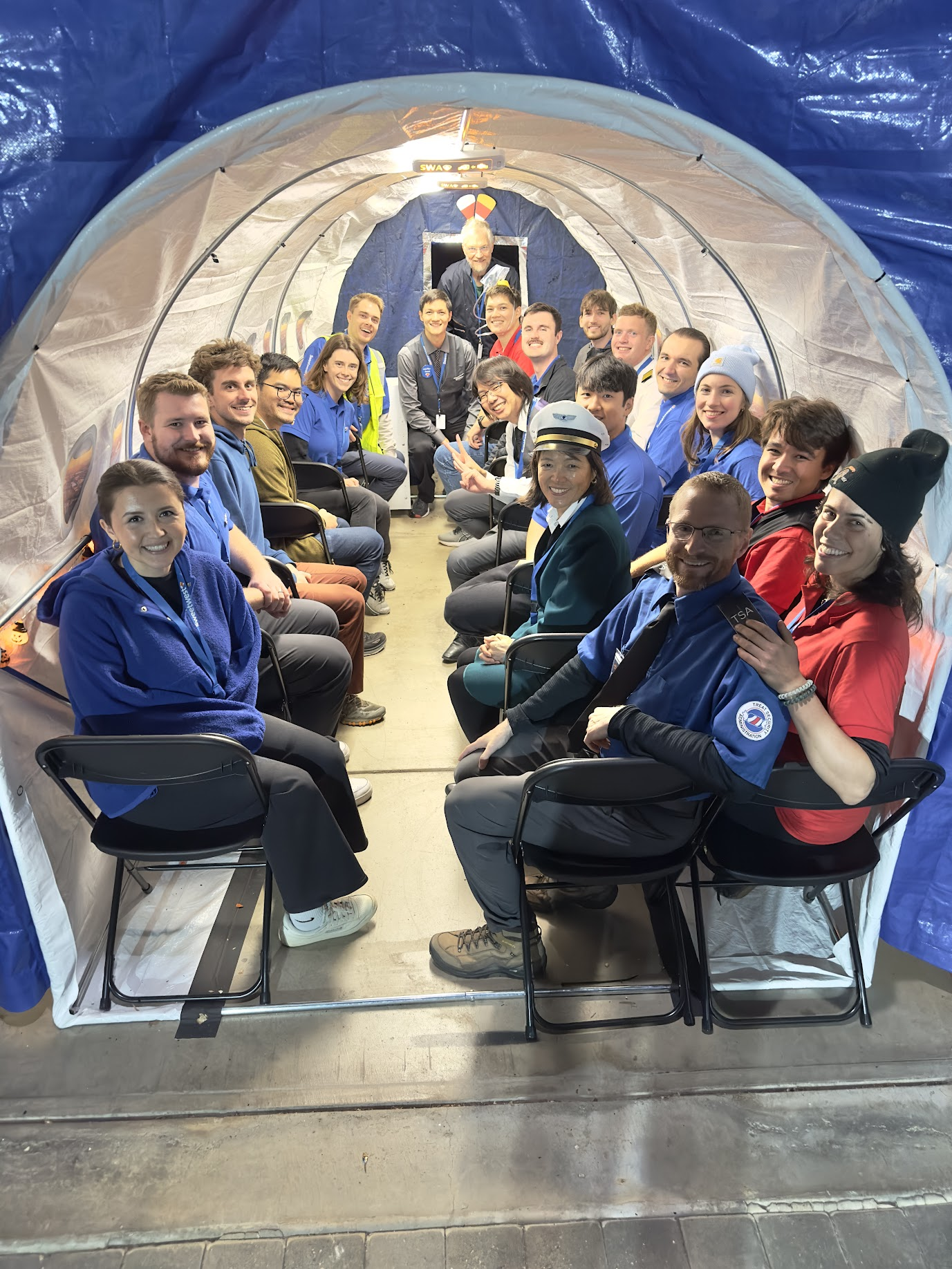
For Halloween of 2024, we decided to tackle a logistically complicated costume idea that had been on our minds for a while: airline travel! Our previous Treat Security Administration costume had demonstrated that kiddos in our area are quite familiar with the routines of travelling through an airport, and that standard airport interactions in the context of the security screening area could be turned into a fun experience for trick-or-treaters. This year, we wanted to go all in and recreate the full airport experience, from booking a ticket to in-flight snacks and entertainment.
Trick-or-treating always involves some element of anarchy, so we wanted the experience to be flexible enough to accommodate the inevitably unpredictable behavior of children on a quest for sugar, while still providing enough structure to be strongly suggestive of a real airport experience. To that end, we decided that theming the event after an airline with an open boarding experience would be advantageous, as it would remove the logistical burden of assigning seats, and would provide increased flexibility for adding or removing passengers from flights at the last minute. Thus, Sweetwest Airlines was born.
The general concept of the Sweetwest Airlines trick-or-treating experience was to have regularly scheduled “flights” to candy-themed destinations in a simulated aircraft. Full-sized candy bars matching the destination candy would be handed out during each flight; for instance, flights to KitKatMandu would hand out full-size KitKat bars, and flights to Twixeltown would hand out full-size Twix bars.
Destination Name
Destination Airport
Snickersville
SNK
Sour Punch Valley
SRP
Twixeltown
TWX
Skittleton
SKT
Kit Katmandu
KKT
Reeses Ridge
RSS
Switzerland
ZRH
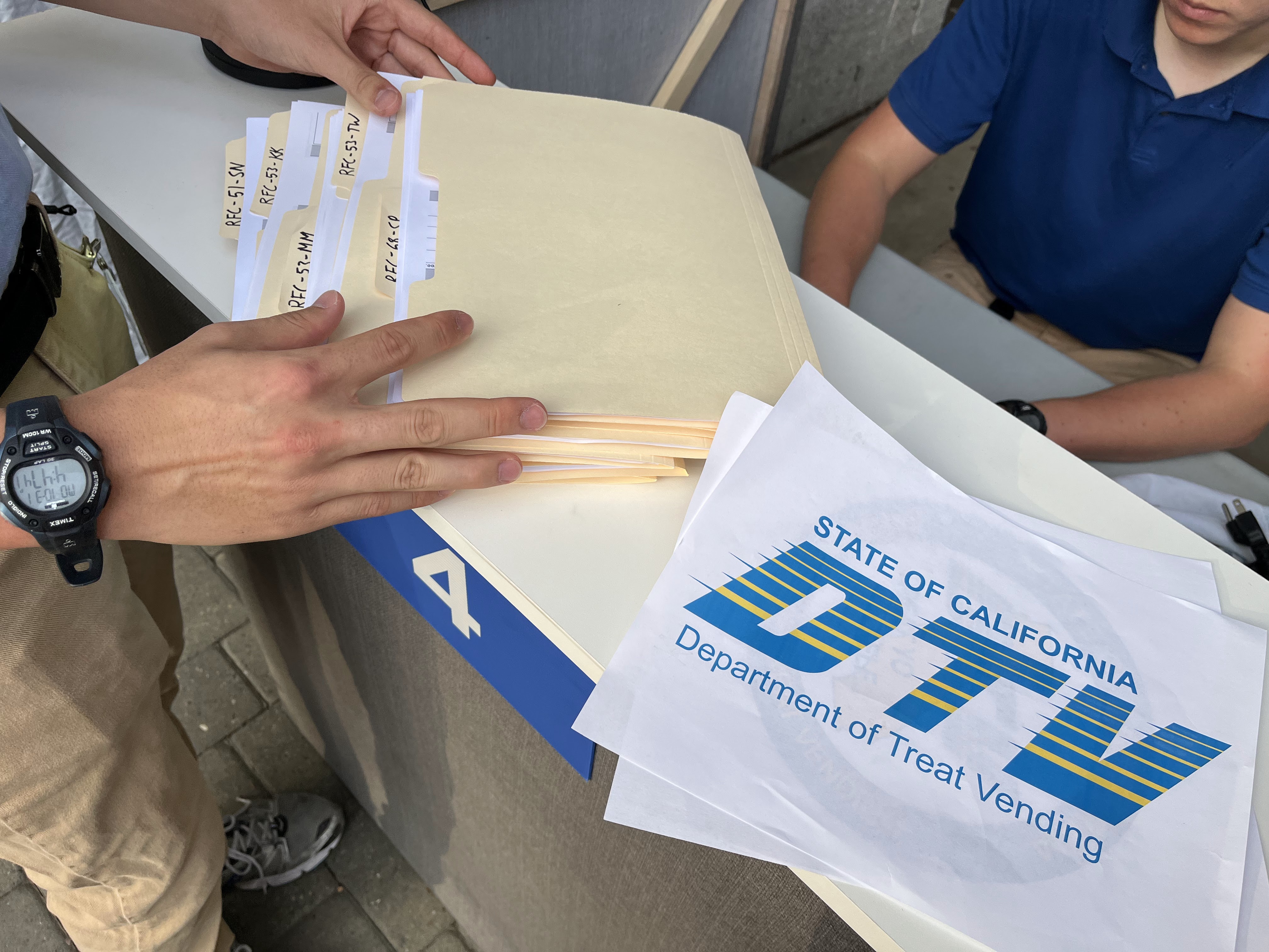
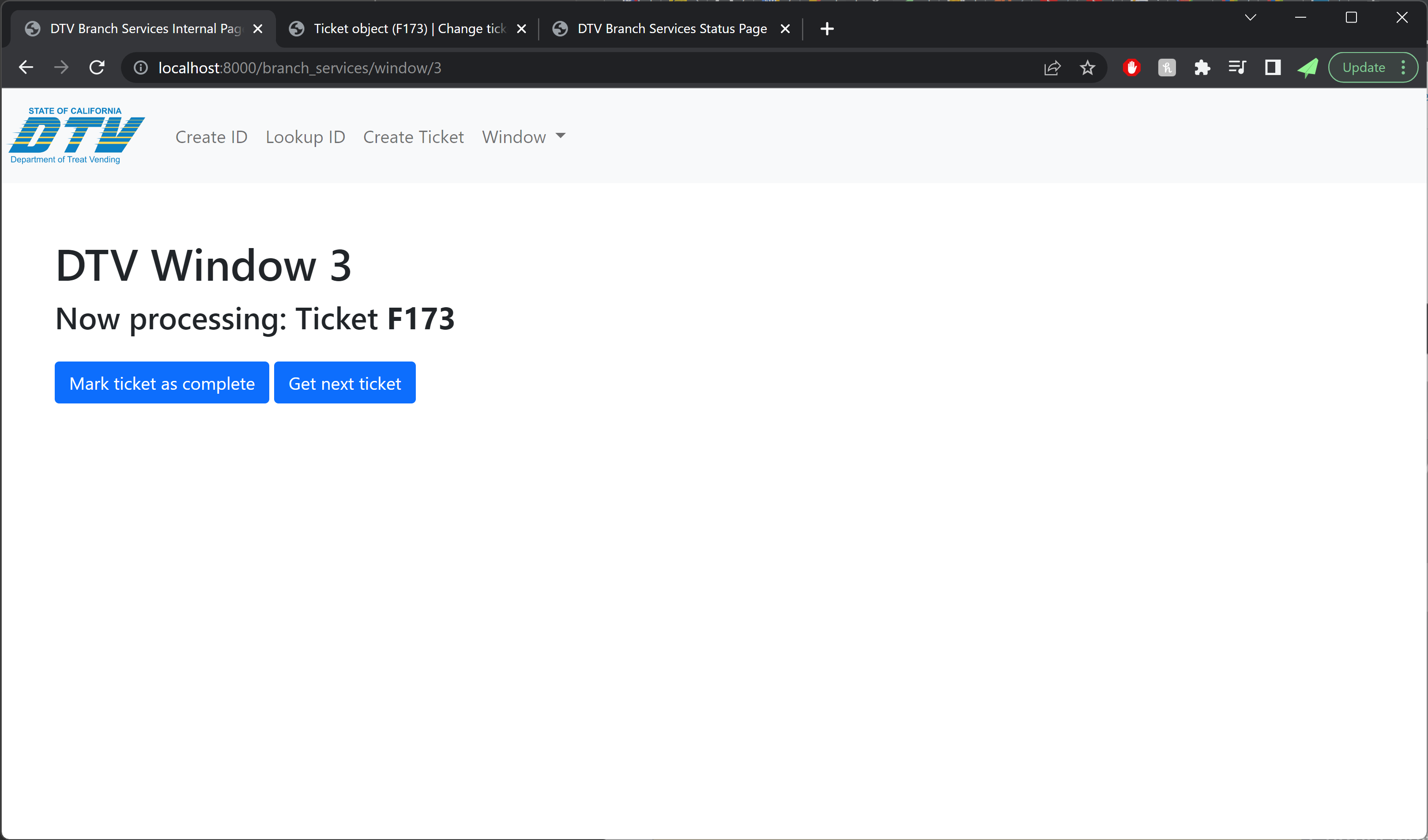
In order to board one of these flights, passengers would need to first acquire a ticket at the ticketing desk (tickets were free, but the line could be quite long). Flights were pre-scheduled with a fixed capacity, so depending on demand at the time, tickets available at the counter might be for a flight leaving in just a few minutes, or up to 90 (maybe more) minutes away. Once a passenger secured a ticket for a given flight, they could opt to wait in the terminal area, or resume trick-or-treating and return to the terminal closer to their given flight time. About seven minutes before a flight’s departure time, a boarding announcement would be made over the airport PA system, asking passengers to line up for boarding. Once the previous flight had de-planed, passengers would have their boarding passes scanned as they boarded the aircraft to enjoy the in-flight experience.
Replying to @Serena Welcome to Sweet West Airlines where your destination is your Candy preference! Guess how many engineers it takes to pull this off !!! And YES everyone loves the ride & experience and if you don’t have time to wait you can go to the front door for candy instead or try & ride stand by! As always can’t take credit for this whole event as we are not the masterminds but just a part of the team 😉 #halloween#trickortreat#sweetwestairlines#airlines#bayarea
Convincing a trick-or-treater that they’ve set foot into an environment that reminds them of an airport is a surprisingly difficult endeavor. Airports are generally very expensive pieces of infrastructure, and transforming a residential driveway into something approximating a billion dollar aircraft terminal would take an ungodly amount of paper mache. Fortunately for us, enough of the airport experience could be recalled through the use of smaller props and employee interactions that five-story-high picture windows and jetways proved to be unnecessary for capturing the essence of the air travel experience.
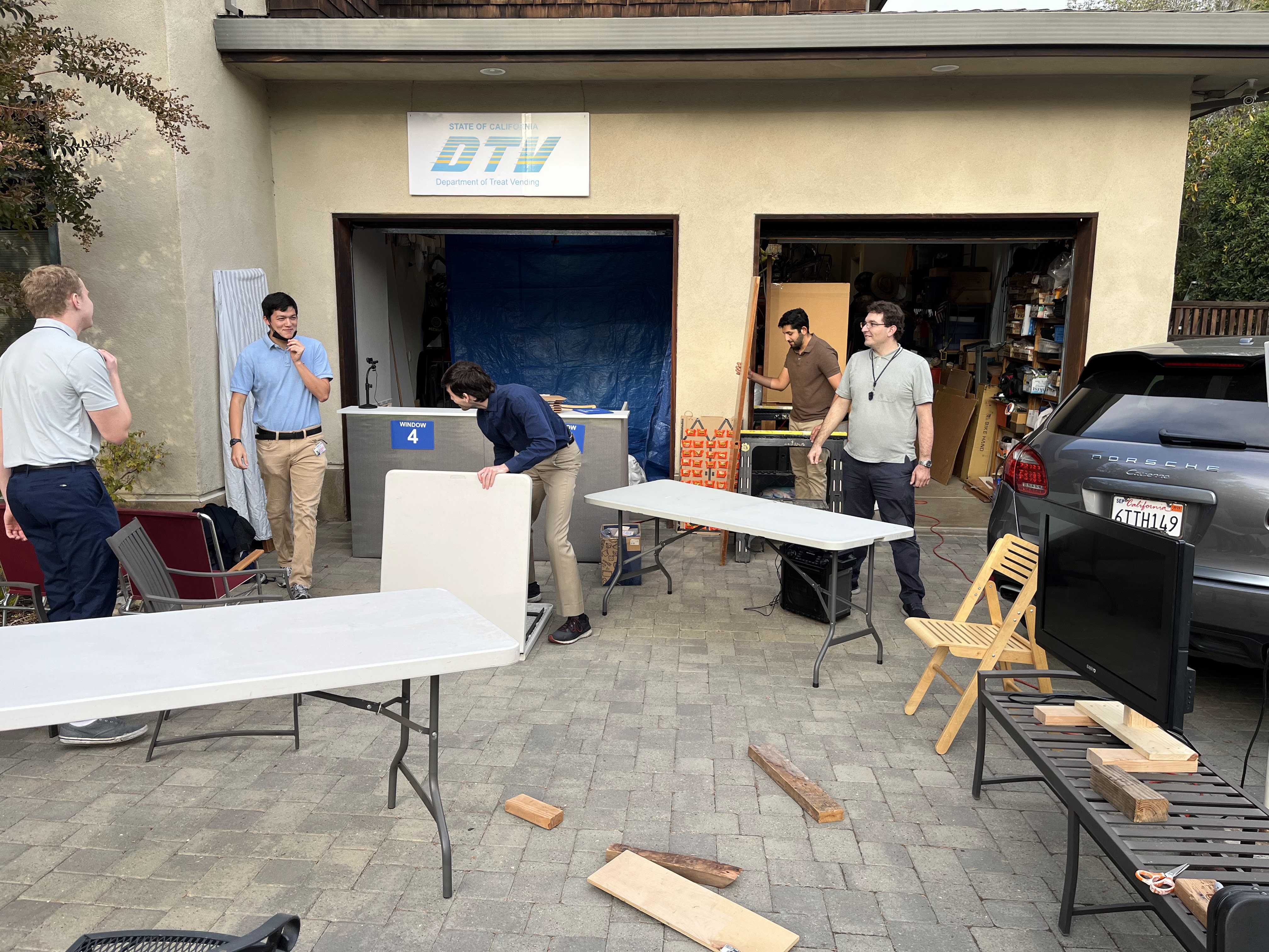
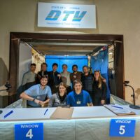
For our airport set, we had four primary set areas: the check-in counter, security / terminal waiting area, the boarding gate, and the aircraft.
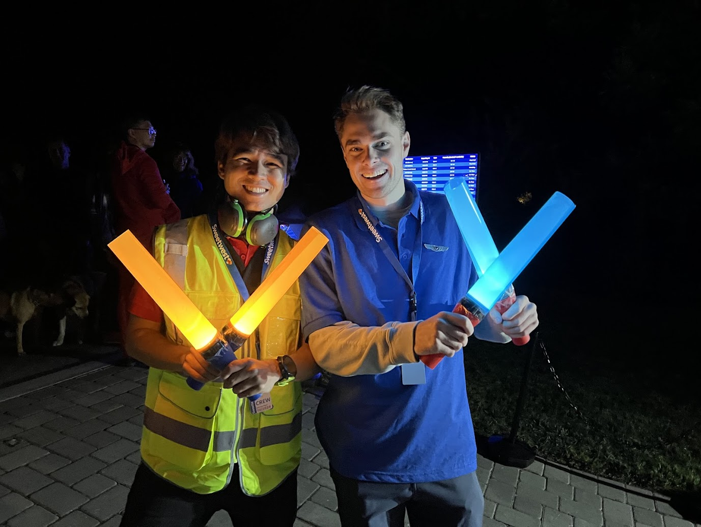
Set Design: Ticket Counter
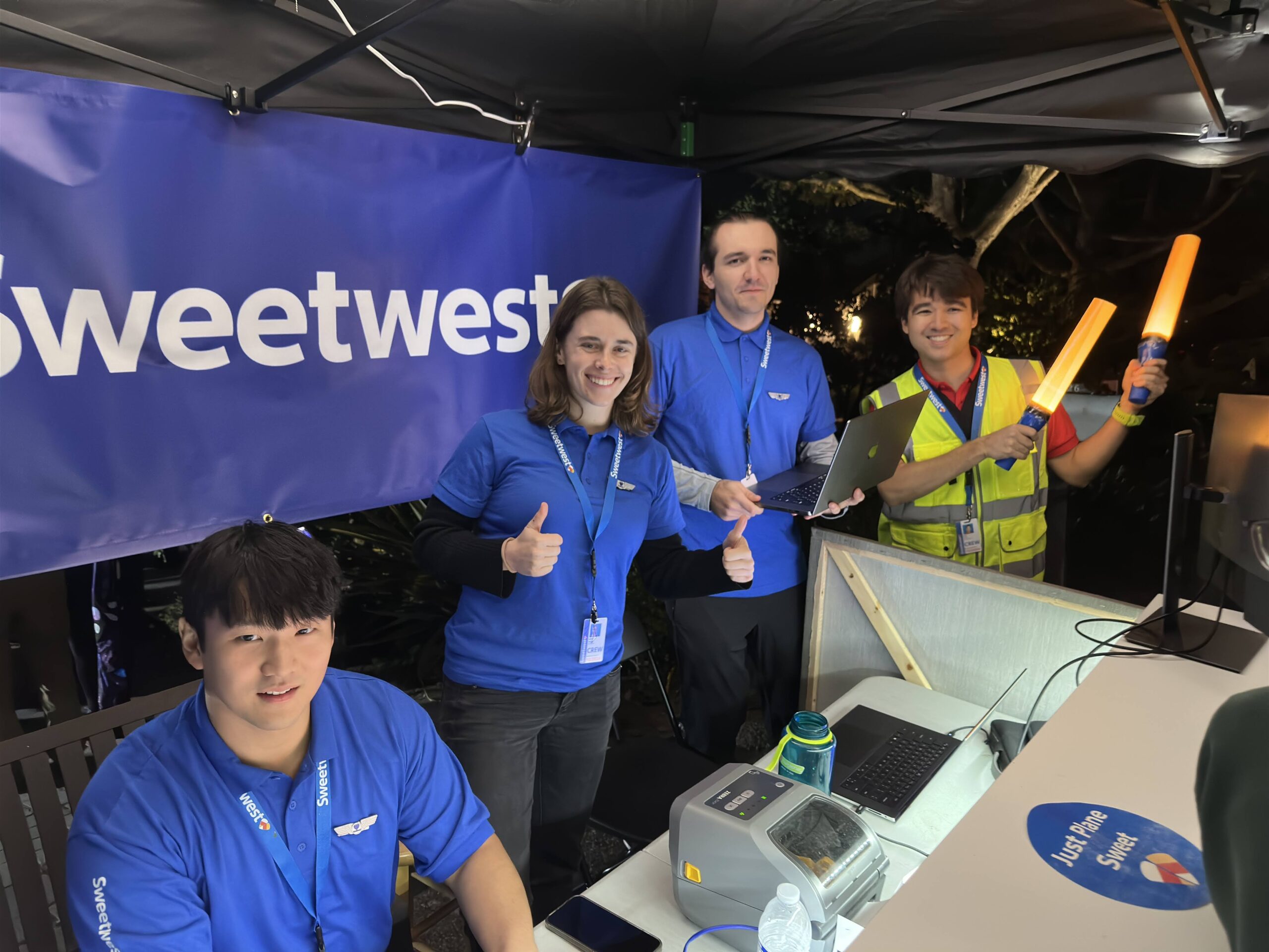
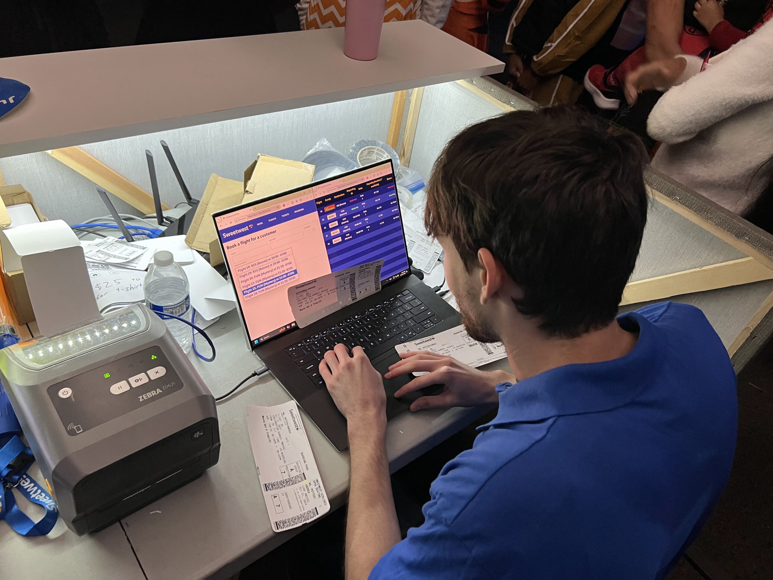
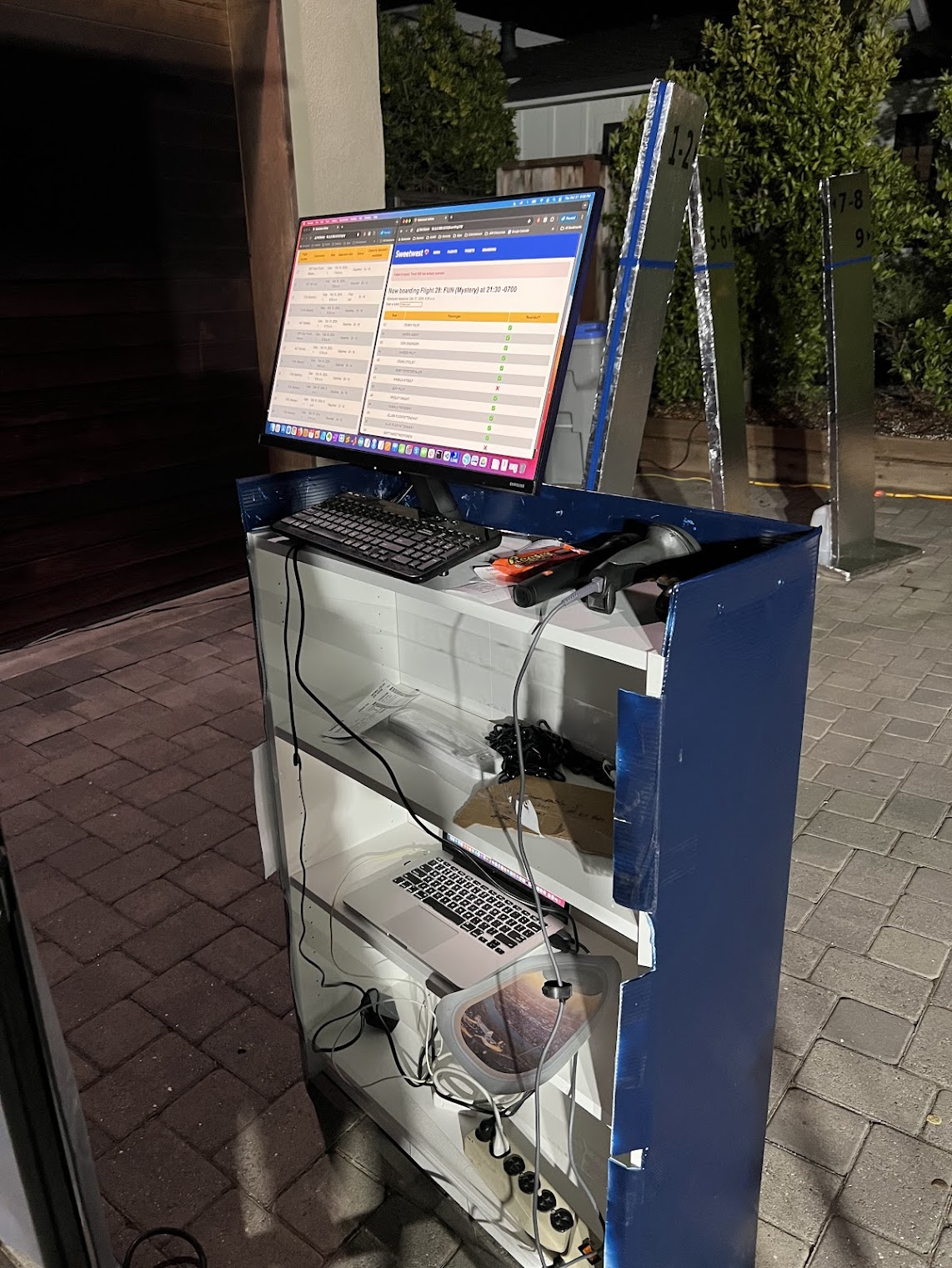
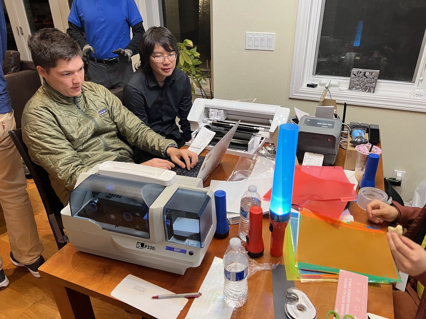
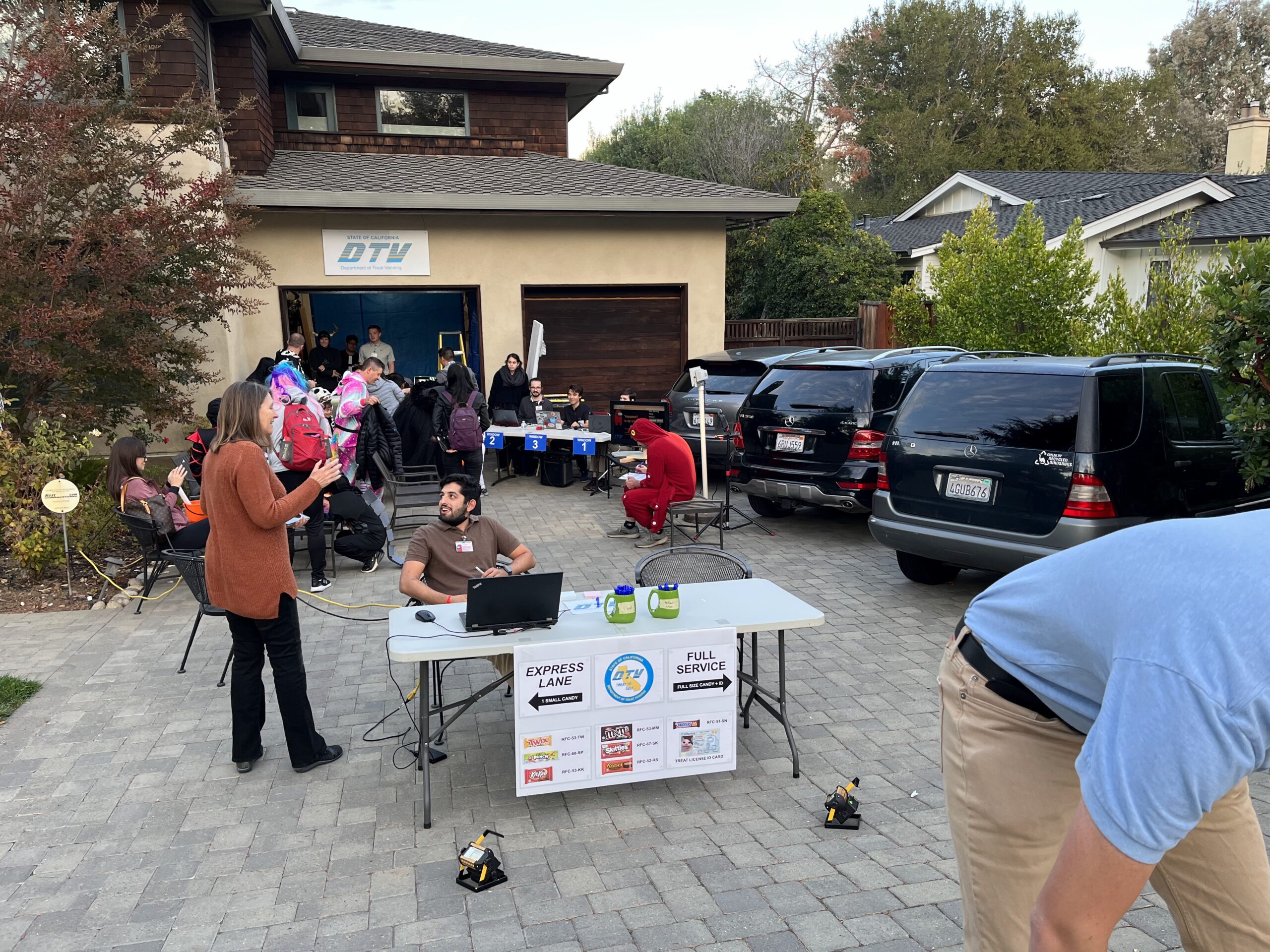
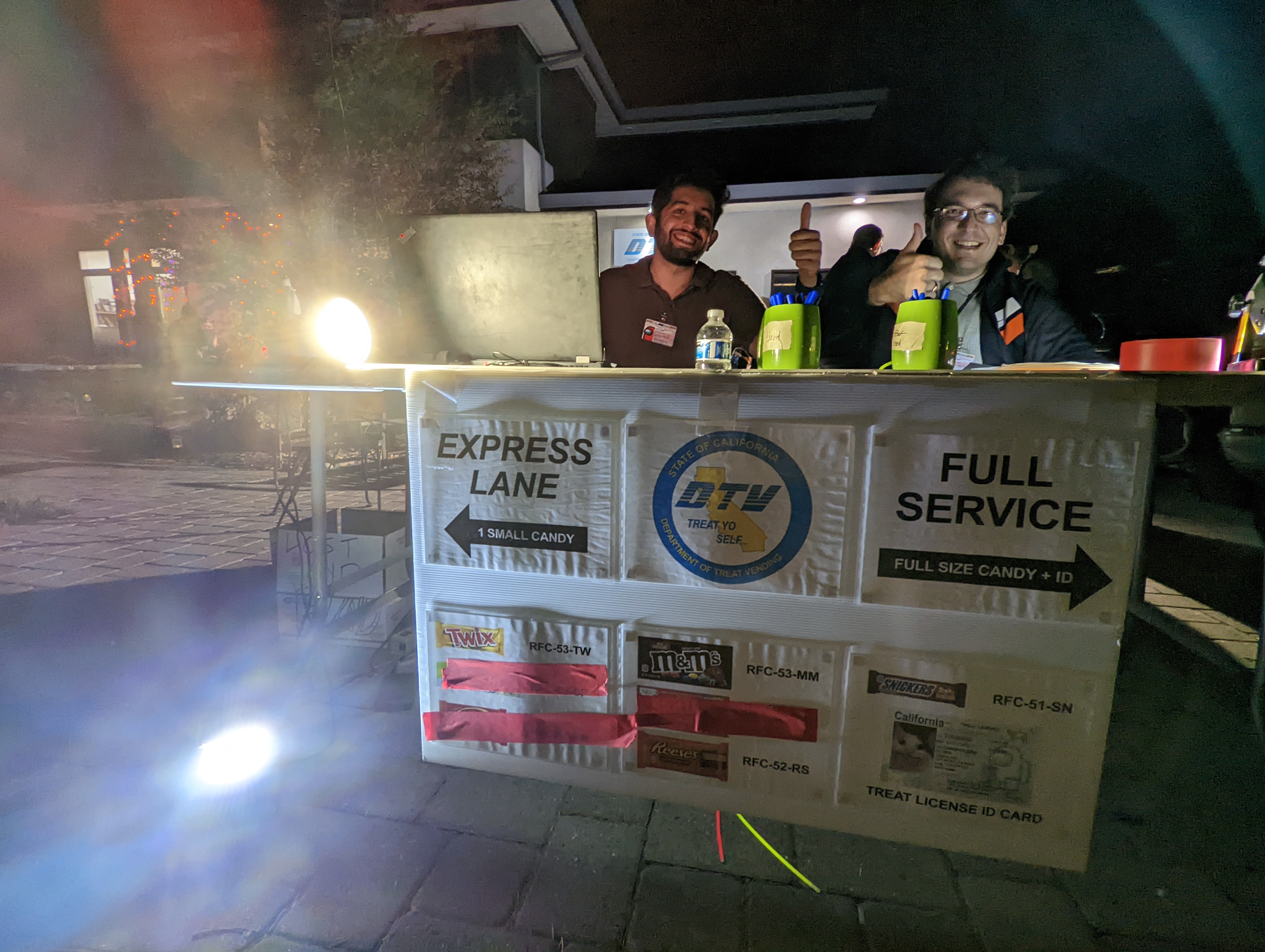
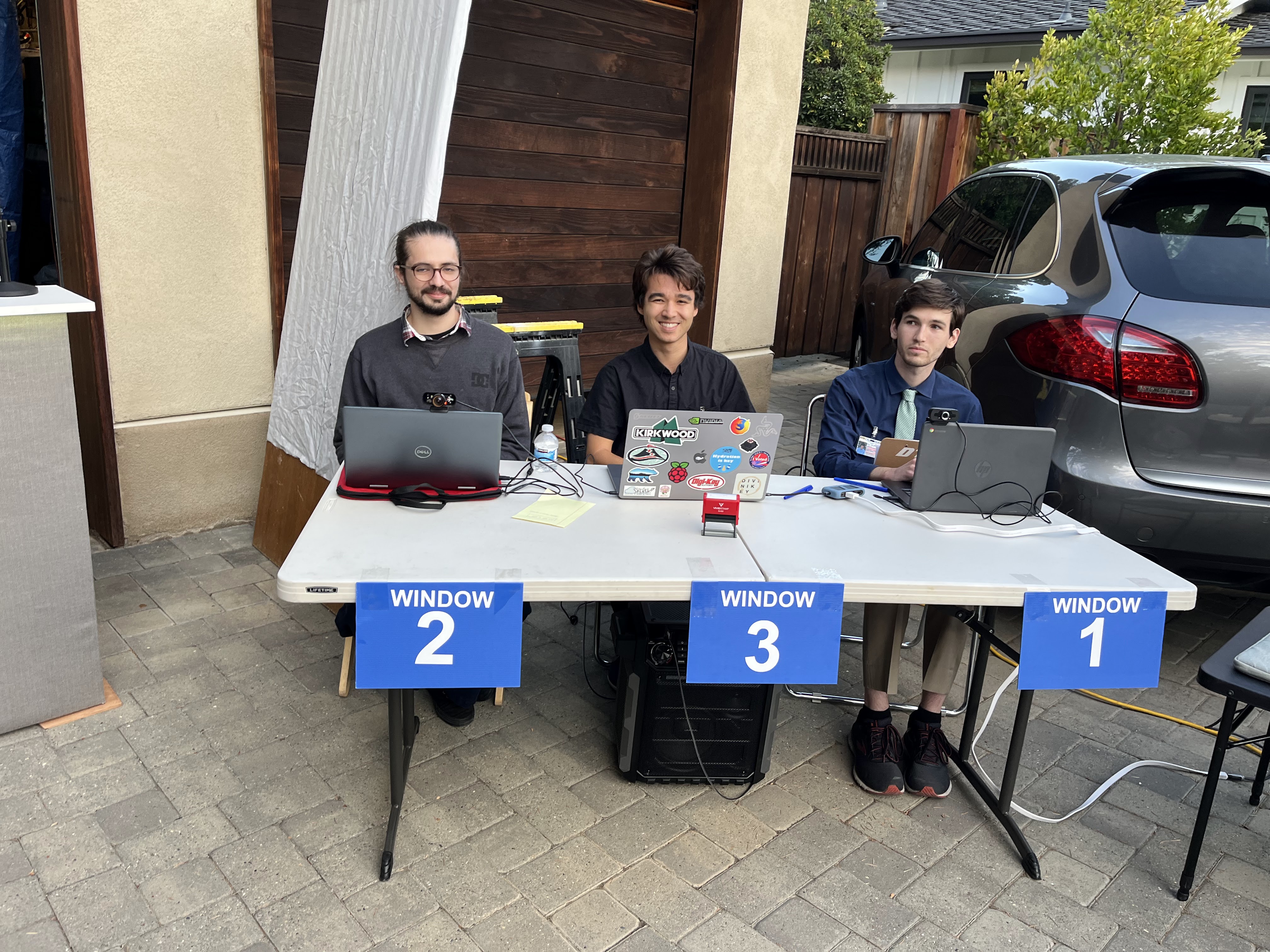
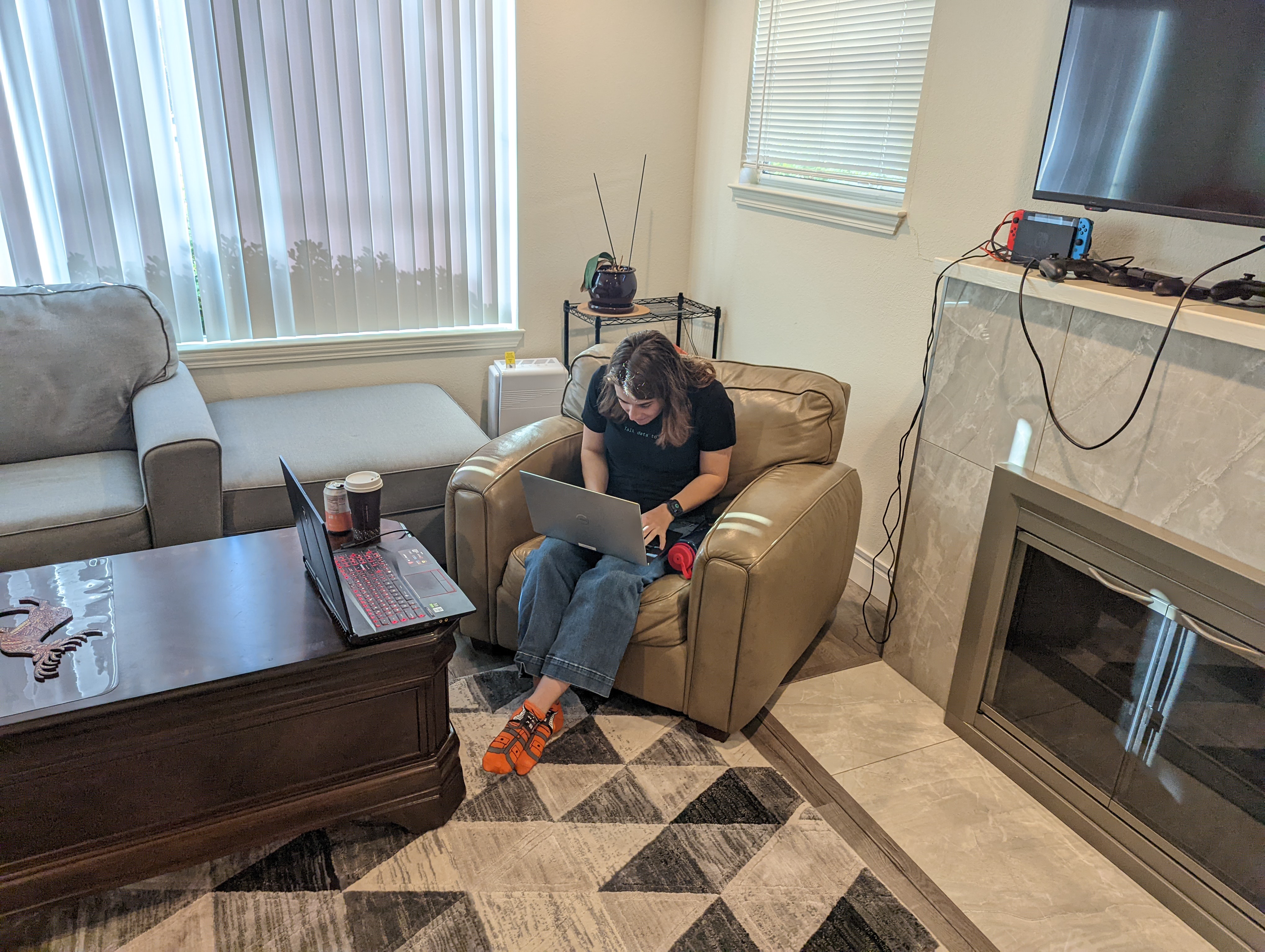
The check-in counter consisted of a 10×10 pop-up tent at the end of the driveway, with a ticket desk and Sweetwest Airlines backdrop. Sweetwest ticket agents used the IT systems built into the ticket desk to show passengers what flights were available and print out boarding passes, and helpers dressed as ramp agents with aircraft marshalling wands helped control crowds on the street and explained where tickets could be purchased. A small monitor at the end of the boarding counter showed passengers the status of upcoming flights, including their destination and departure time.
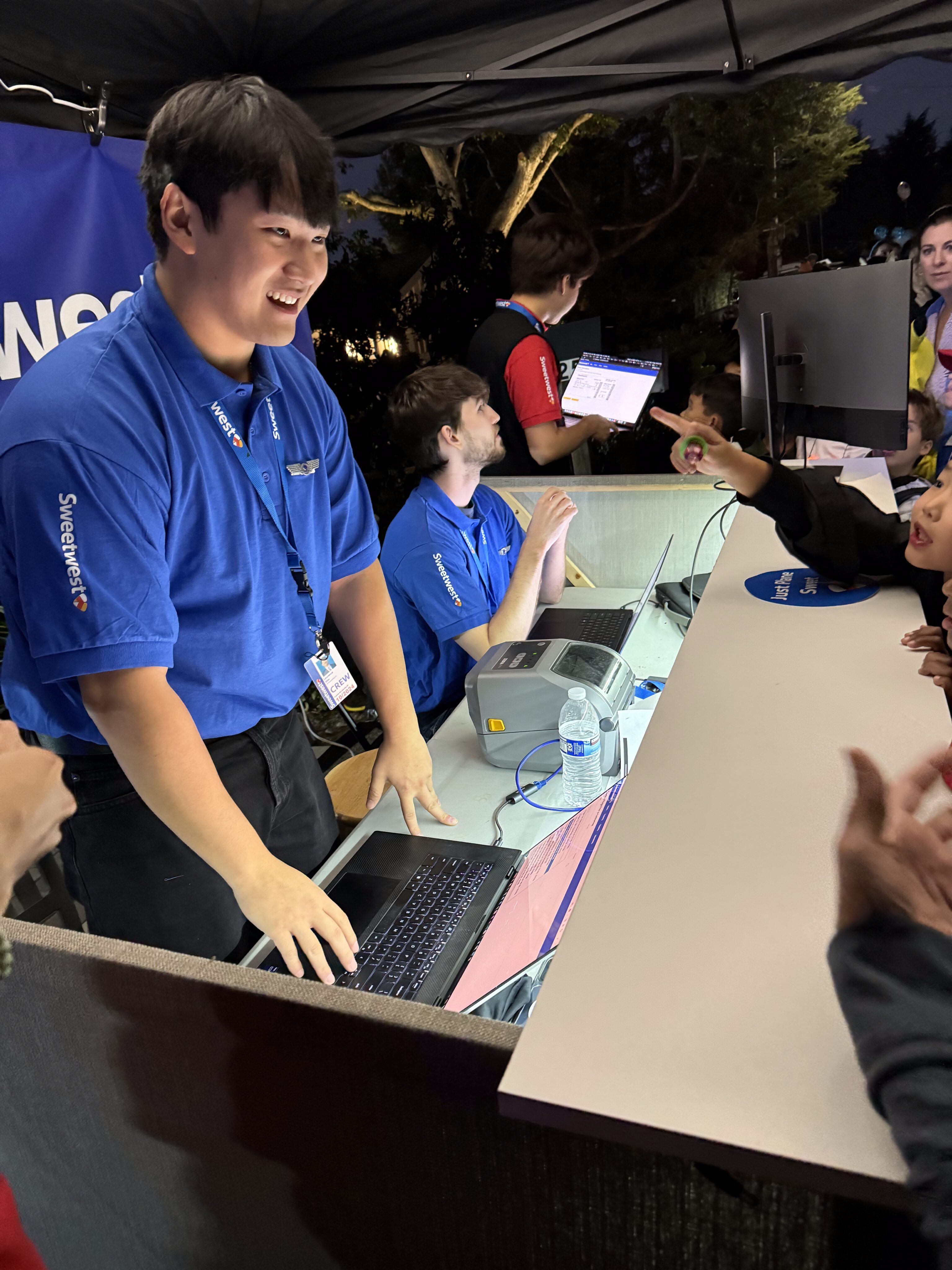
Agents at the ticket counter used laptops that were connected to the central IT system to enable them to view upcoming flights, book tickets, and print tickets. The ticket counter also served as the IT hub for the entire costume, as the router running the ethernet link to the boarding display and ticket counter, as well as the laptop running the IT system webserver, were located on the counter.
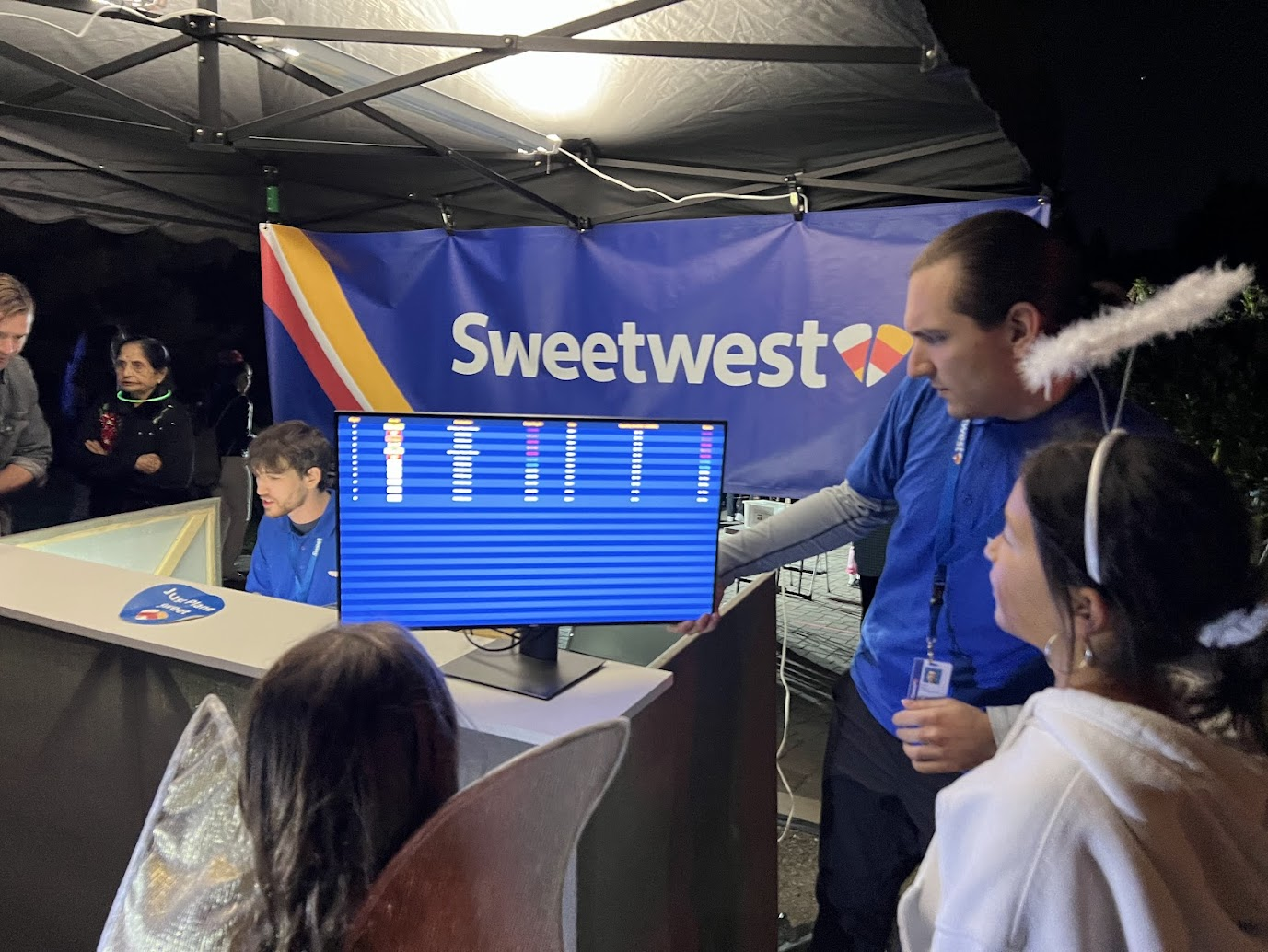
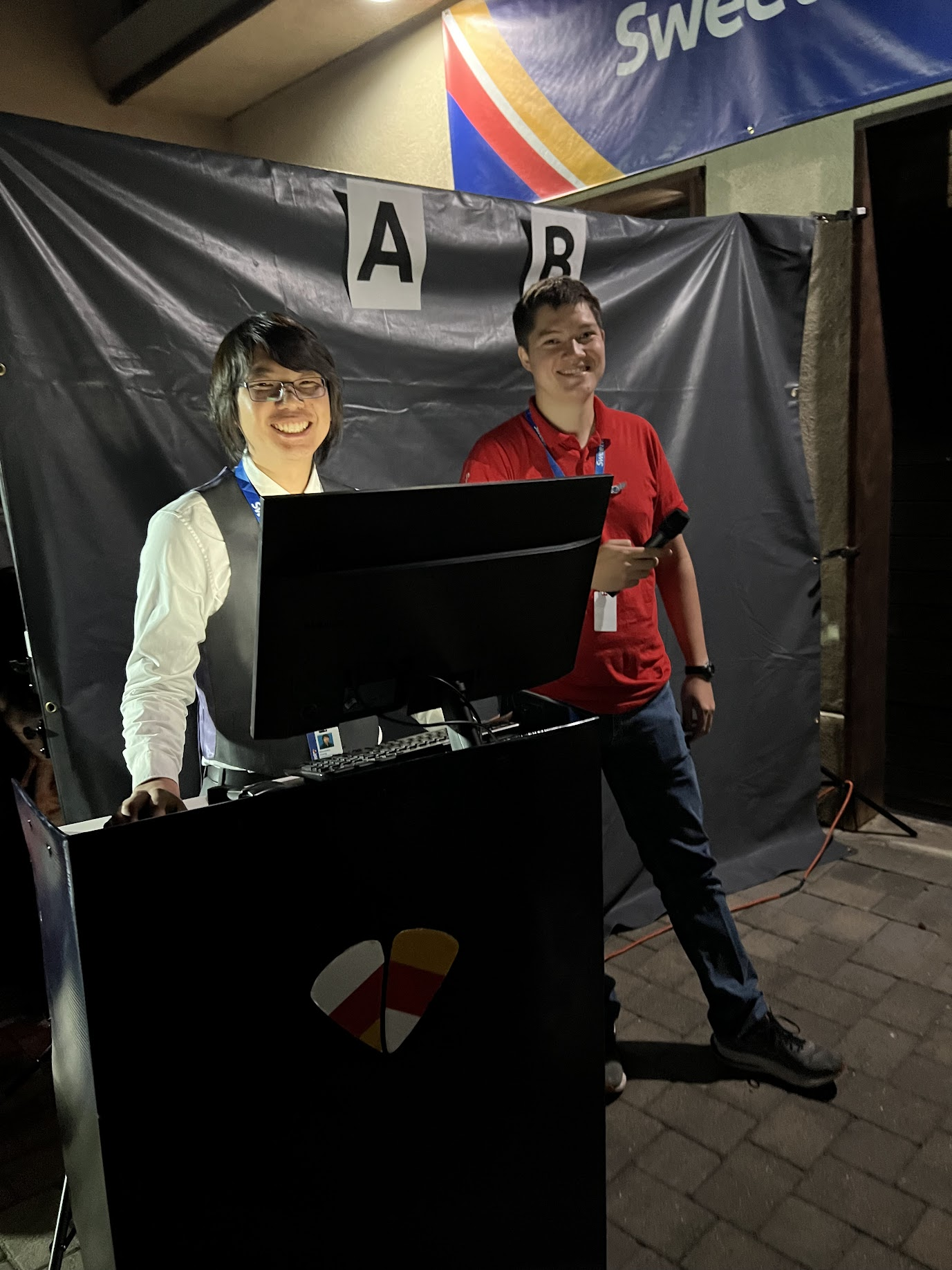
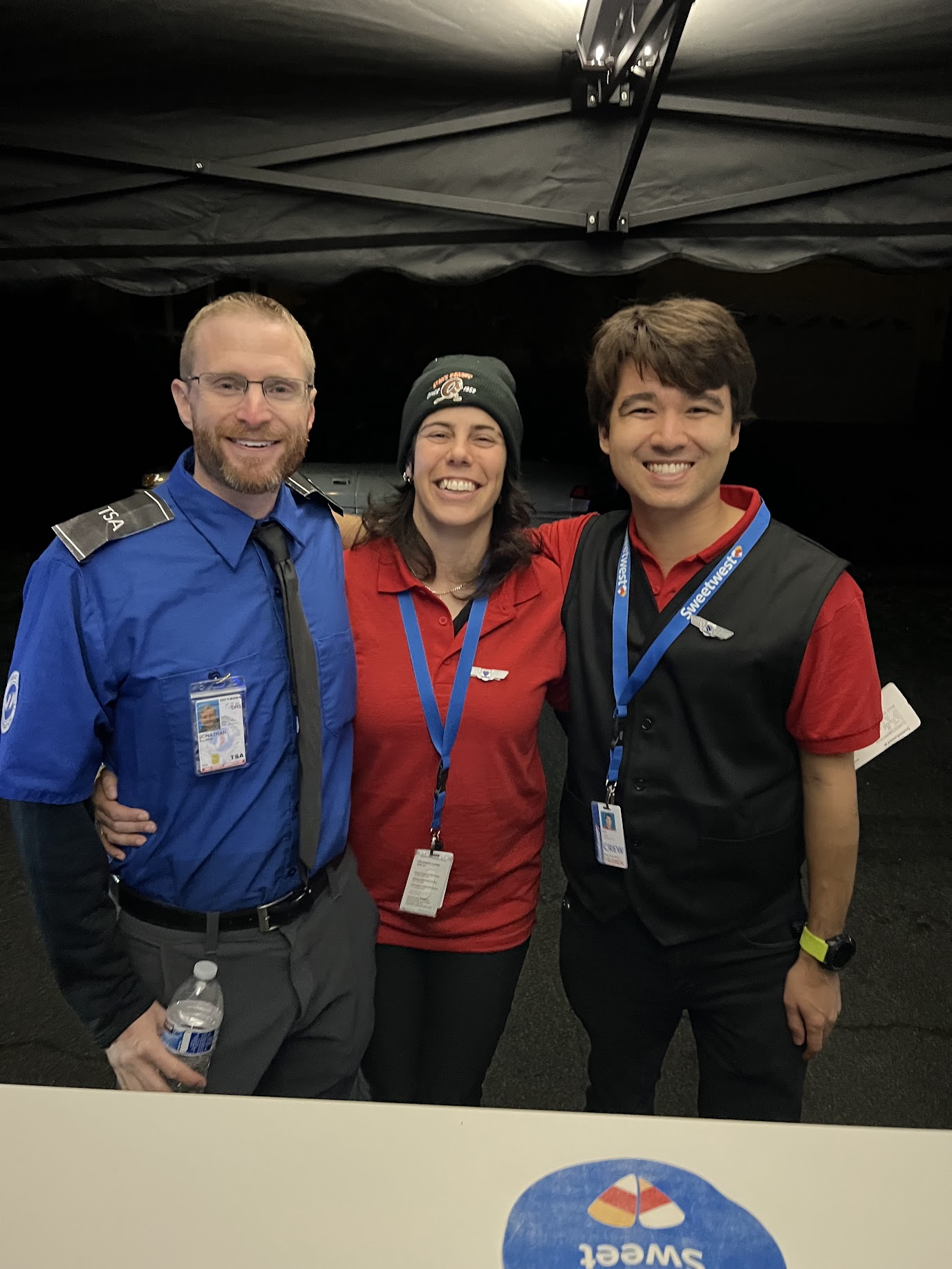
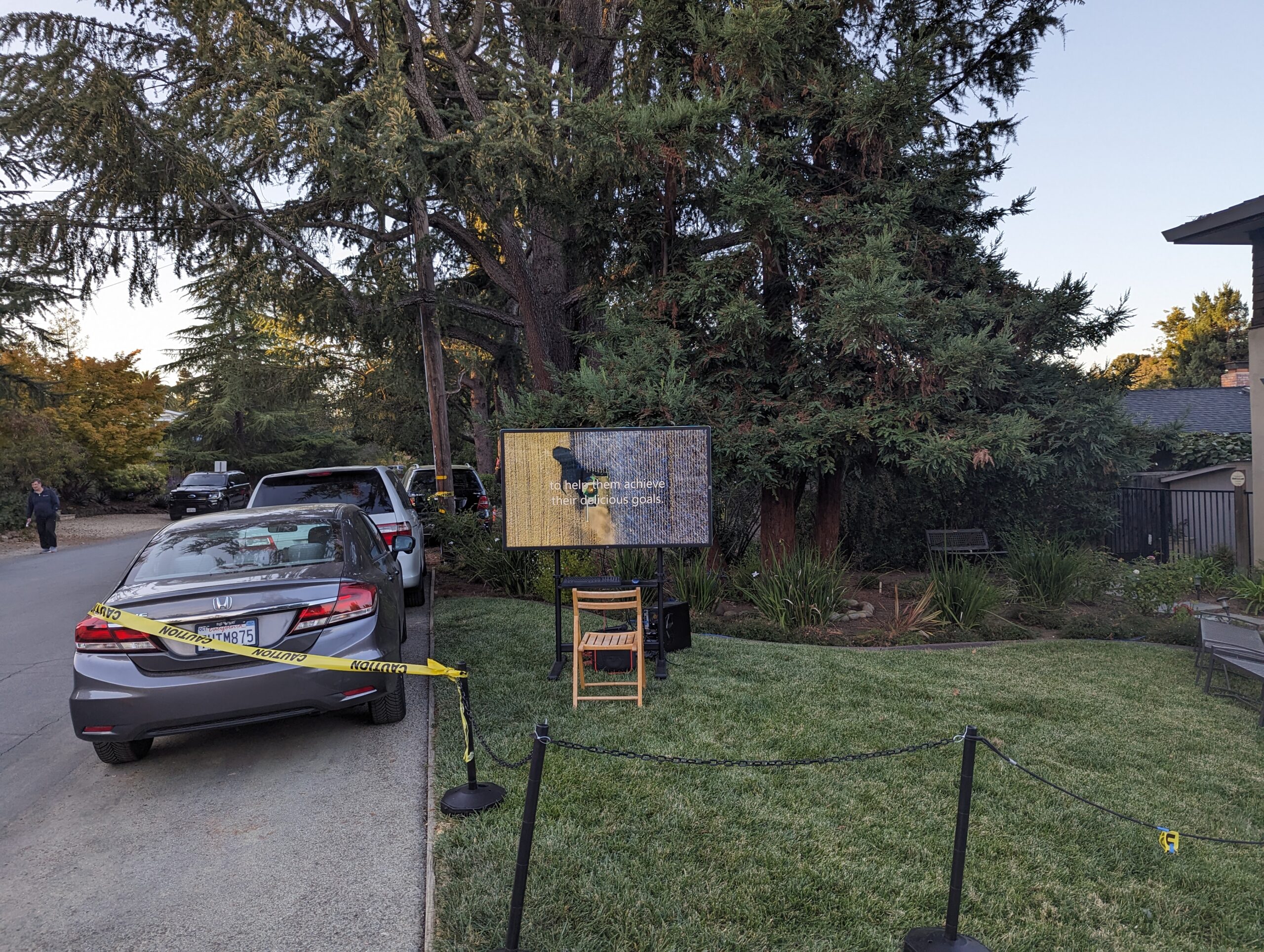
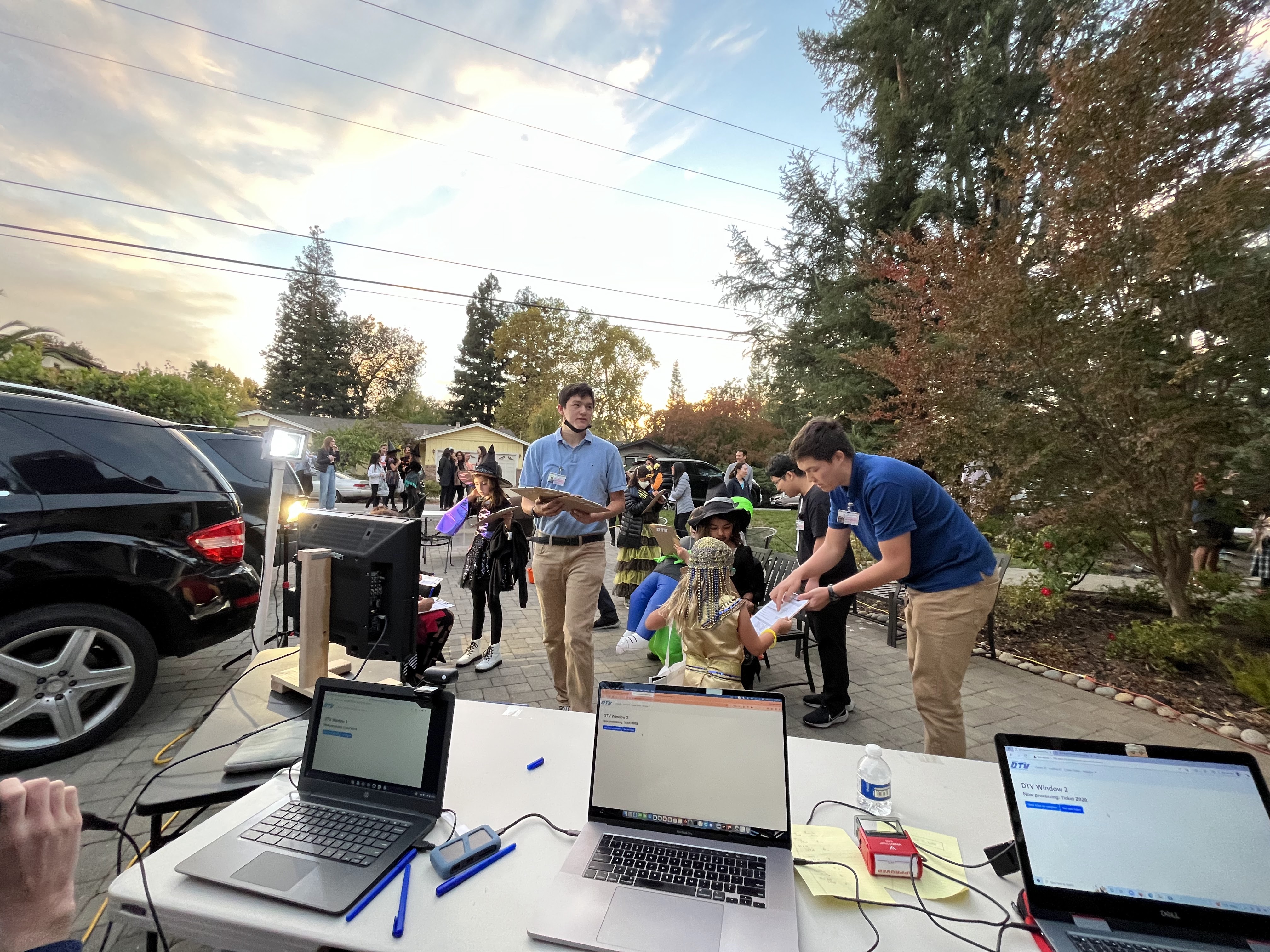
Set Design: Terminal / Waiting Area
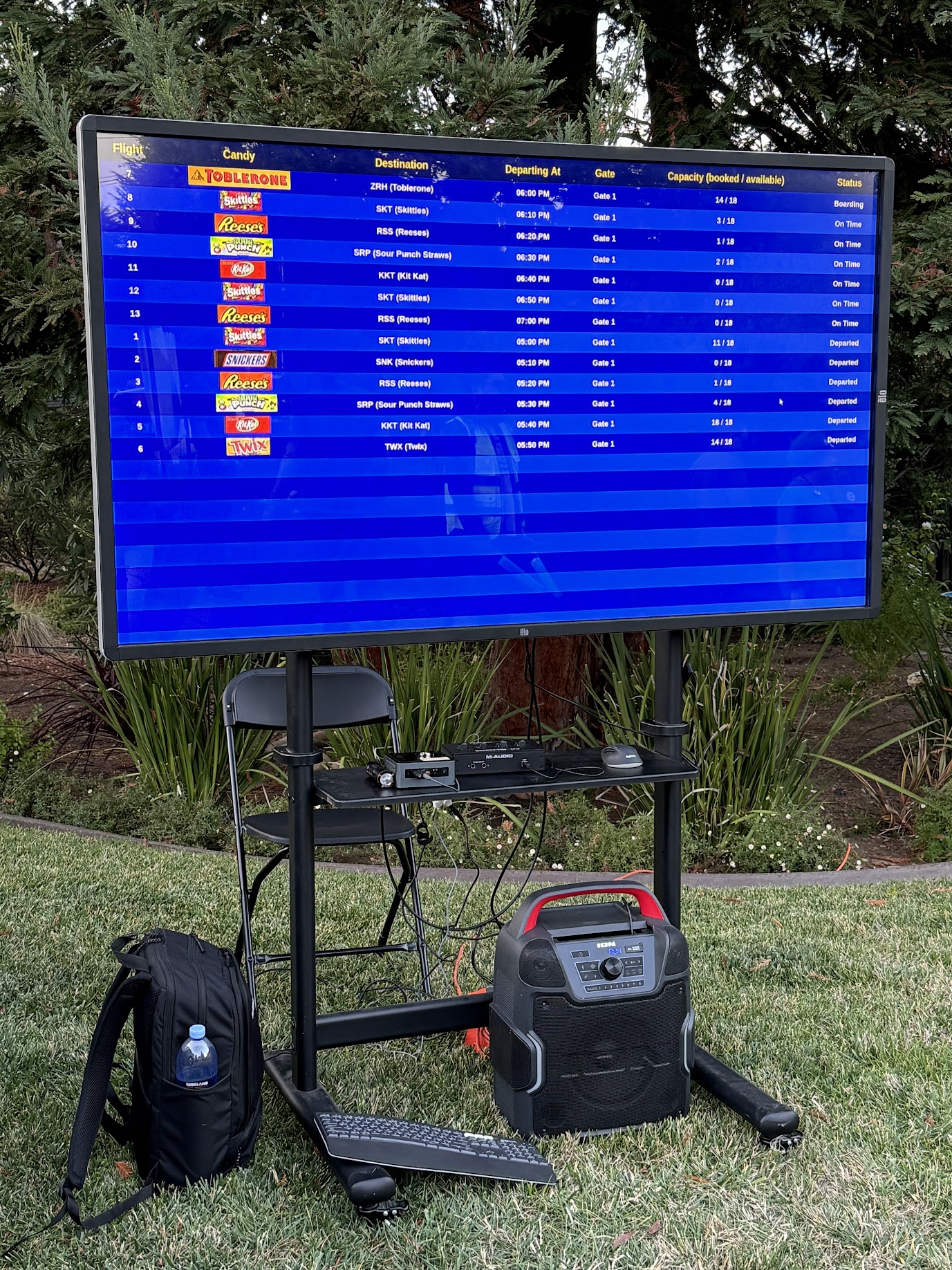
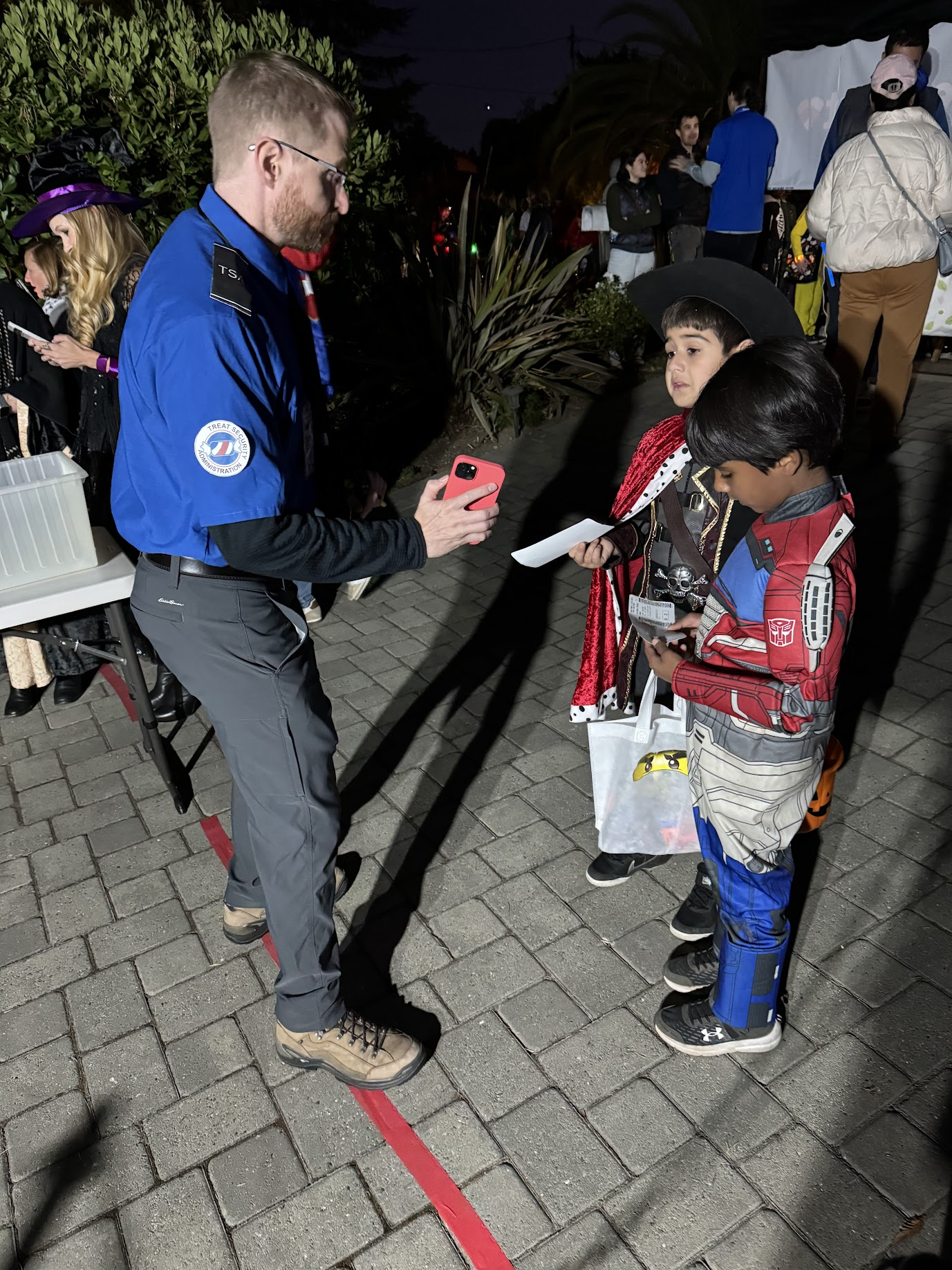
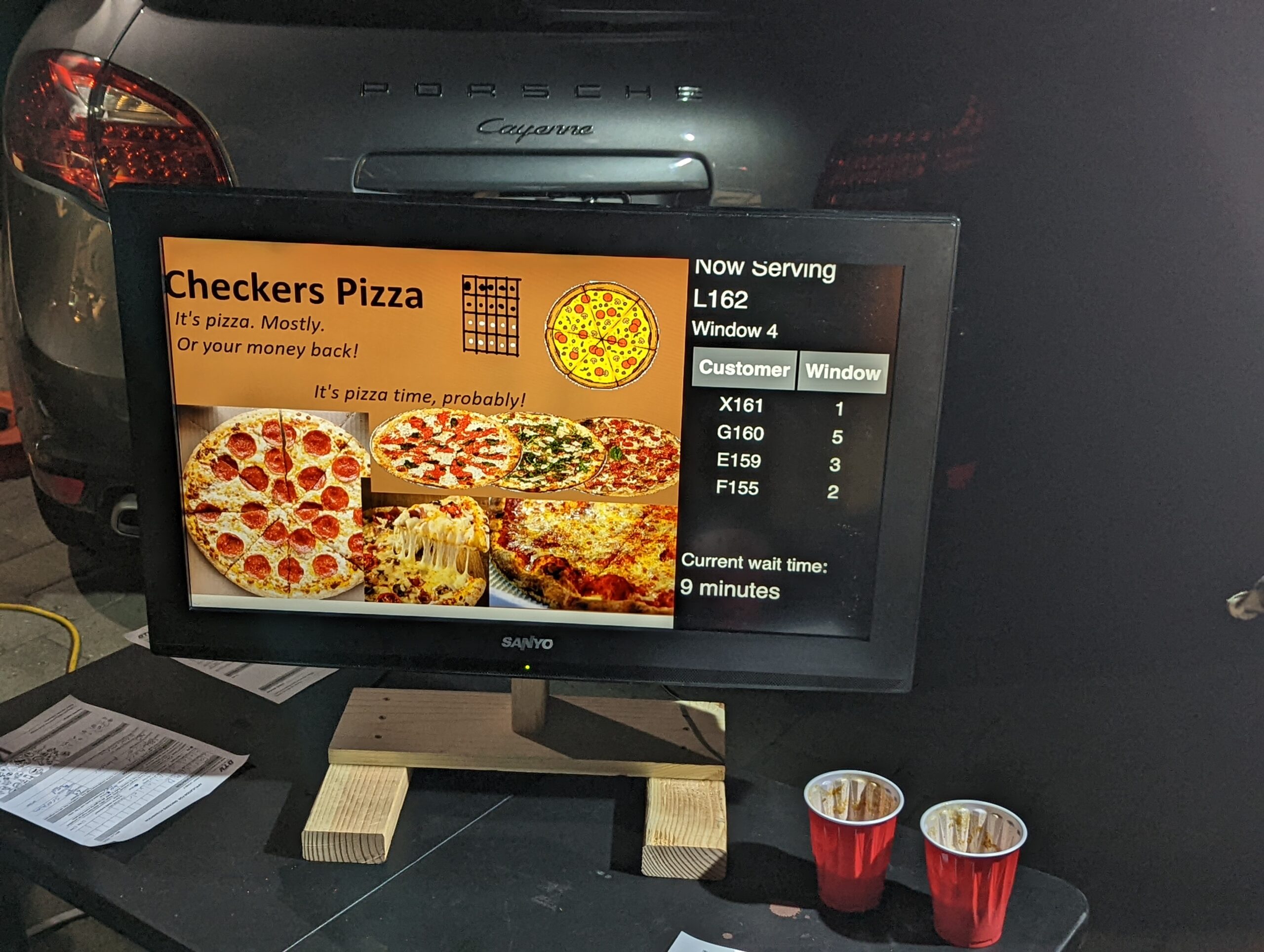
The terminal area included most of the driveway behind the ticket counter, as well as a portion of the lawn to the left of the driveway. A large monitor was used to display flight information, and a custom audio system was developed to provide terminal announcements (with trademark bing-bong audio cues and purposeful audio enshittification to emulate a terminal PA system). With the quantity of moving parts already in play, we decided against setting up the full-fledged TSA checkpoint we had built a few years back, and instead had two Treat Security Agents that passengers needed to interact with before passing into the secure waiting area. Our Treat Security Agents performed their jobs admirably, ensuring that all passengers entering the boarding area had valid boarding passes and understood the boarding process. Thanks to their dedicated efforts, the number of Confused Passengers was greatly reduced, and there were zero attempted aircraft hijackings for the duration of the evening.
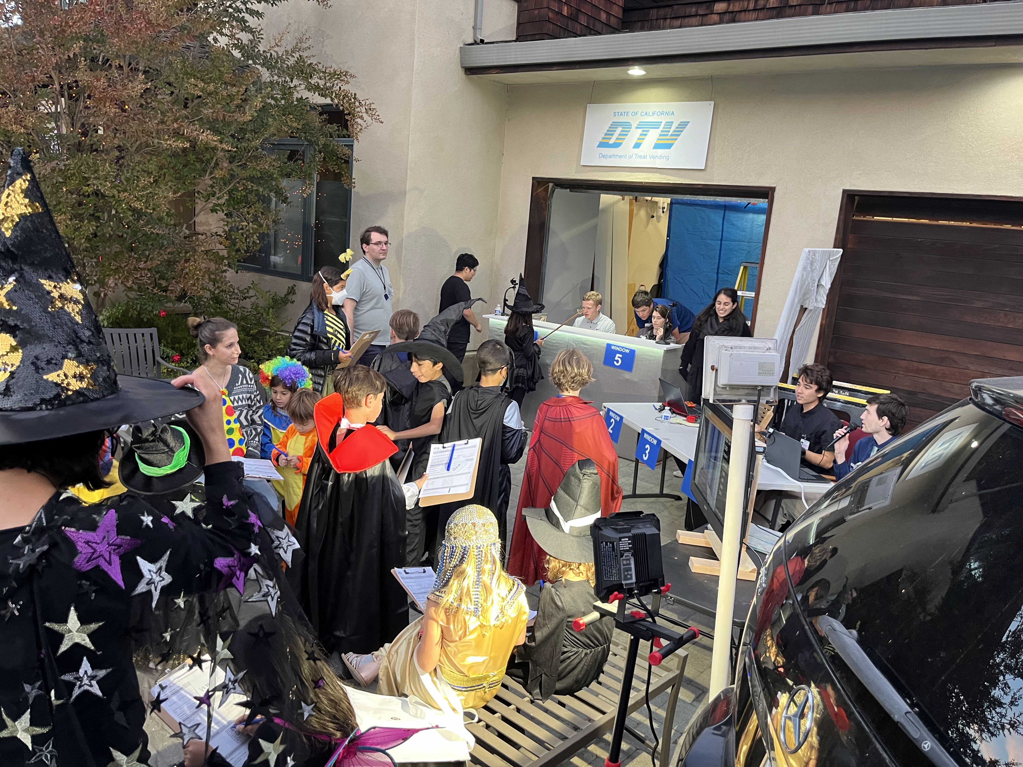
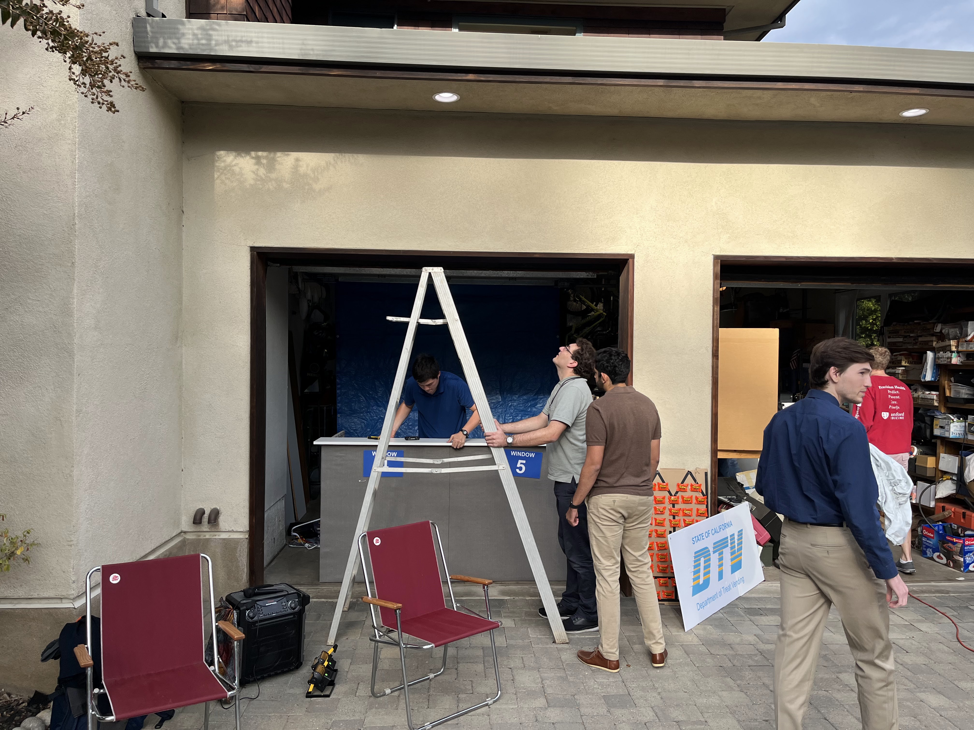
Set Design: Boarding Gate
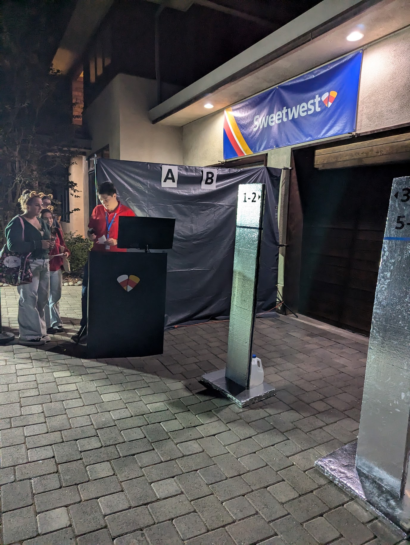
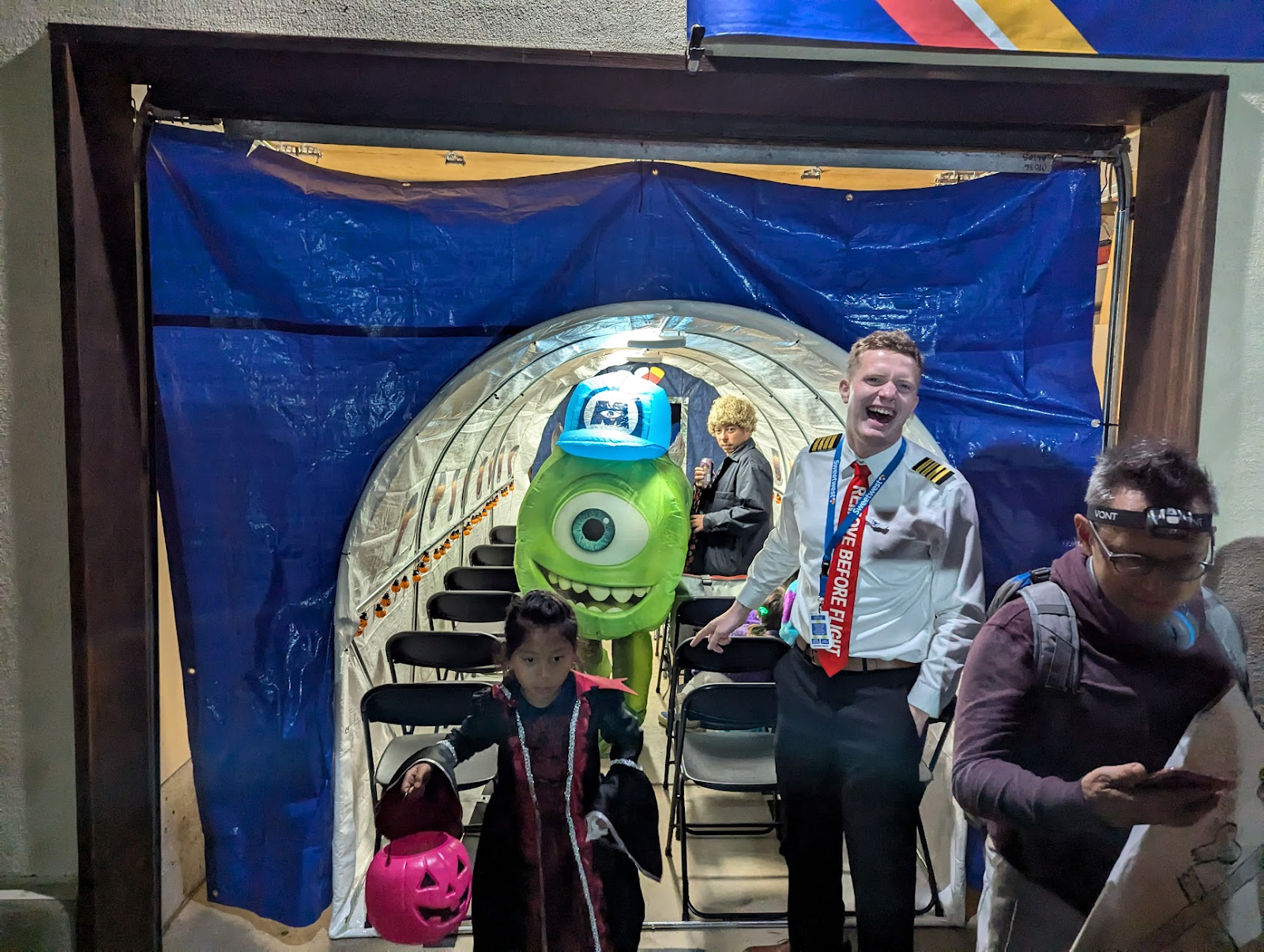
The boarding gate was designed to emulate a standard Southwest Airlines airport gate with as few materials as possible. In addition to providing a place for the Boarding Experience™, the gate served to corral passengers and provide some semblance of separation between the aircraft and the airport (primarily through the liberal use of a large tarp and a wonderfully absorptive blob of parents pulling double duty as sound insulation for passengers in the aircraft).
While planning the set design, we realized that there were a few important components to the Boarding Experience™ that we needed to capture.
Waiting for boarding to begin, only to realize that they are boarding a different group.
The slight air of superiority emanating from people in said group as they walk past you.
Southwest specific: finding your spot in line next to the numbered boarding pillars. “Are you 54? I’m 53.” (apologetic)
The barcode scanner that needs to scan everyone’s boarding pass, but refuses to scan every fifth pass until the gate agent tries one more time.
Loud airport announcements, including boarding calls and final calls for specific passengers that are stuck in line at Starbucks or about to miss their flight in another manner.
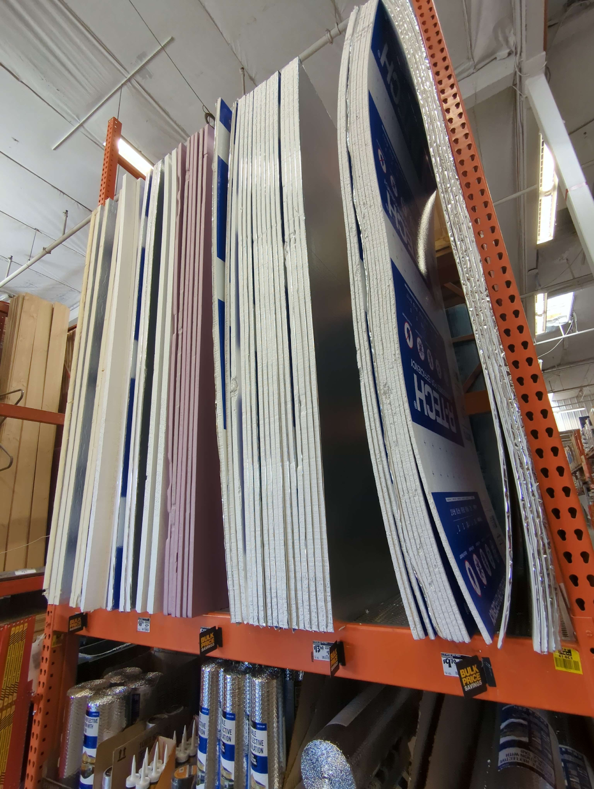
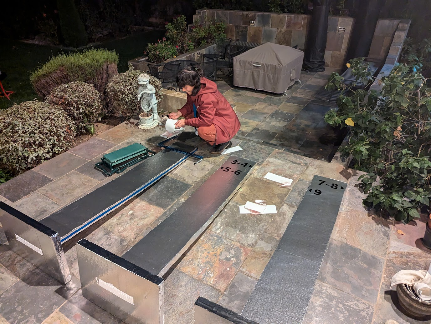
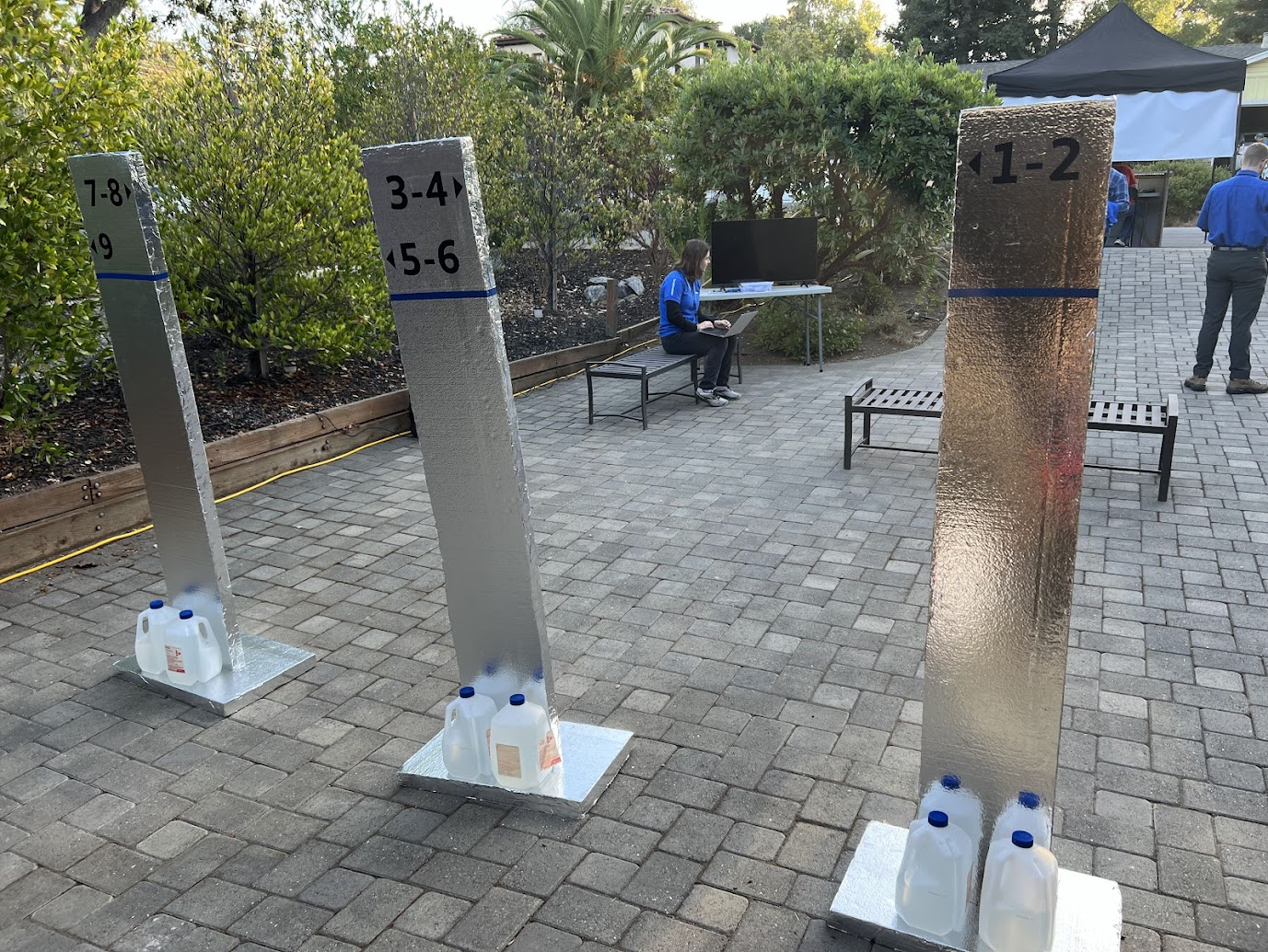
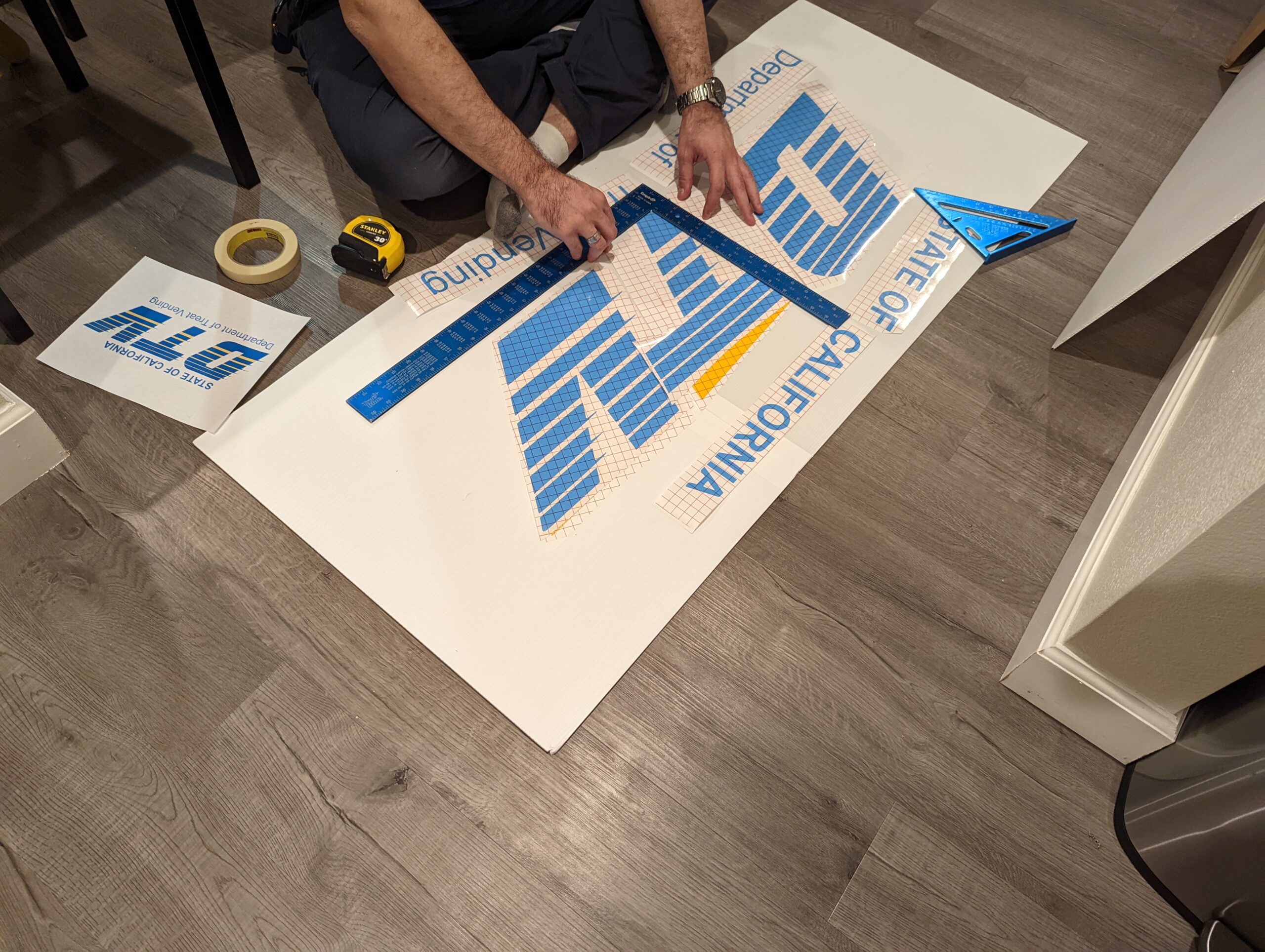
These goals were readily accomplished with the fabrication of a few set pieces. For the boarding pillars, we needed something cheap and light enough that it wouldn’t hurt anyone if it fell over. Gluing some foil-backed insulation foam sheets together (shiny side out) turned out to be perfect for this, and adding the blue accents (electrical tape) and numbering (black vinyl) was a breeze. We did encounter an issue with the pillars tipping over too easily, but this was remedied with the addition of some gallon jugs of water at the base of the pillars.
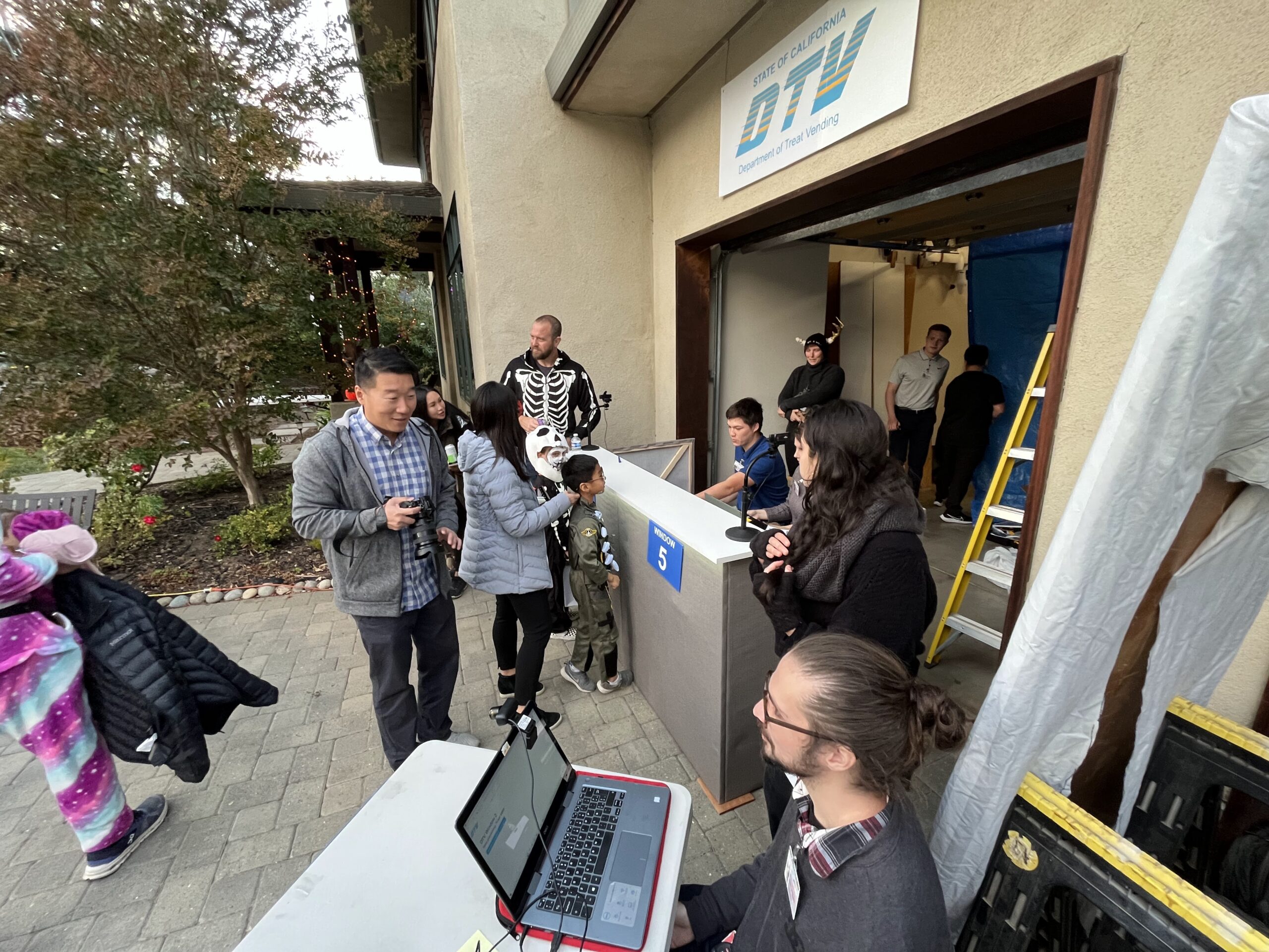
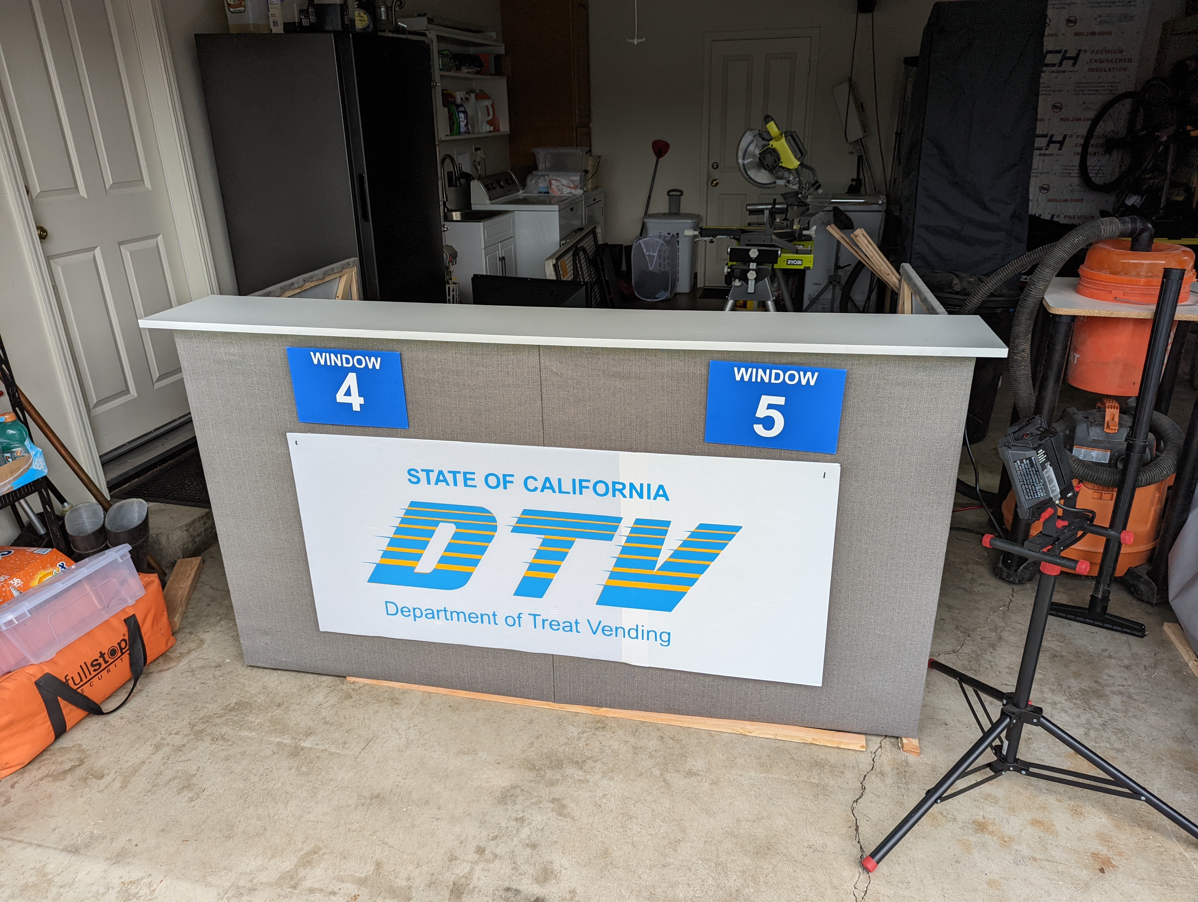
For the boarding podium, we wrapped an IKEA bookshelf in painted coroplast, and added a Sweetwest Airlines logo cut out of paper. The gate agent was provided with a laptop and a barcode scanner that was capable of reading PDF417 barcodes. Importantly, the barcode scanner provided was purchased from eBay as “Parts Only – Not Working”. It scanned codes just fine, but with a reliability rate of around 80%–perfect.
Gate announcements were made over the airport PA system (more details on this later), letting passengers know when flights were beginning to board, when the next boarding group was being called, which passengers were missing, and when flights were departing.
Here’s another closeup of the boarding counter, including the ancient Macbook being used to run it, and a window that fell off of the airplane. It fell off during a flight–we shrugged and said “it’s a Boeing”. People laughed, people ate candy, we reattached the window with spray adhesive. Good times.
Set Design: The Airplane
Since we didn’t have 120 million dollars on hand for an actual Boeing 737, we had to get creative while designing a set for the in-flight experience portion of the costume. We had a few key design criteria for the aircraft:
Fits into a single car garage.
Seats 16 passengers.
“Feel like” an airplane (can’t just be some tape on the ground).
Allows parents to have direct line of sight to their children (e.g. can’t close the garage door).
Wide enough aisle to allow food service with a cart.
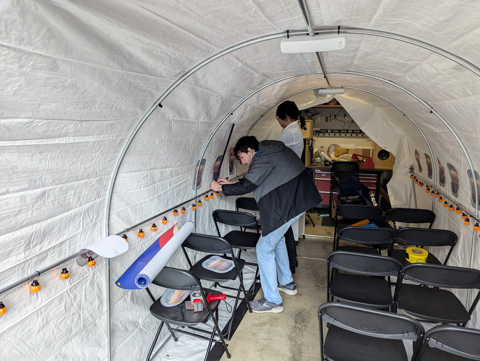
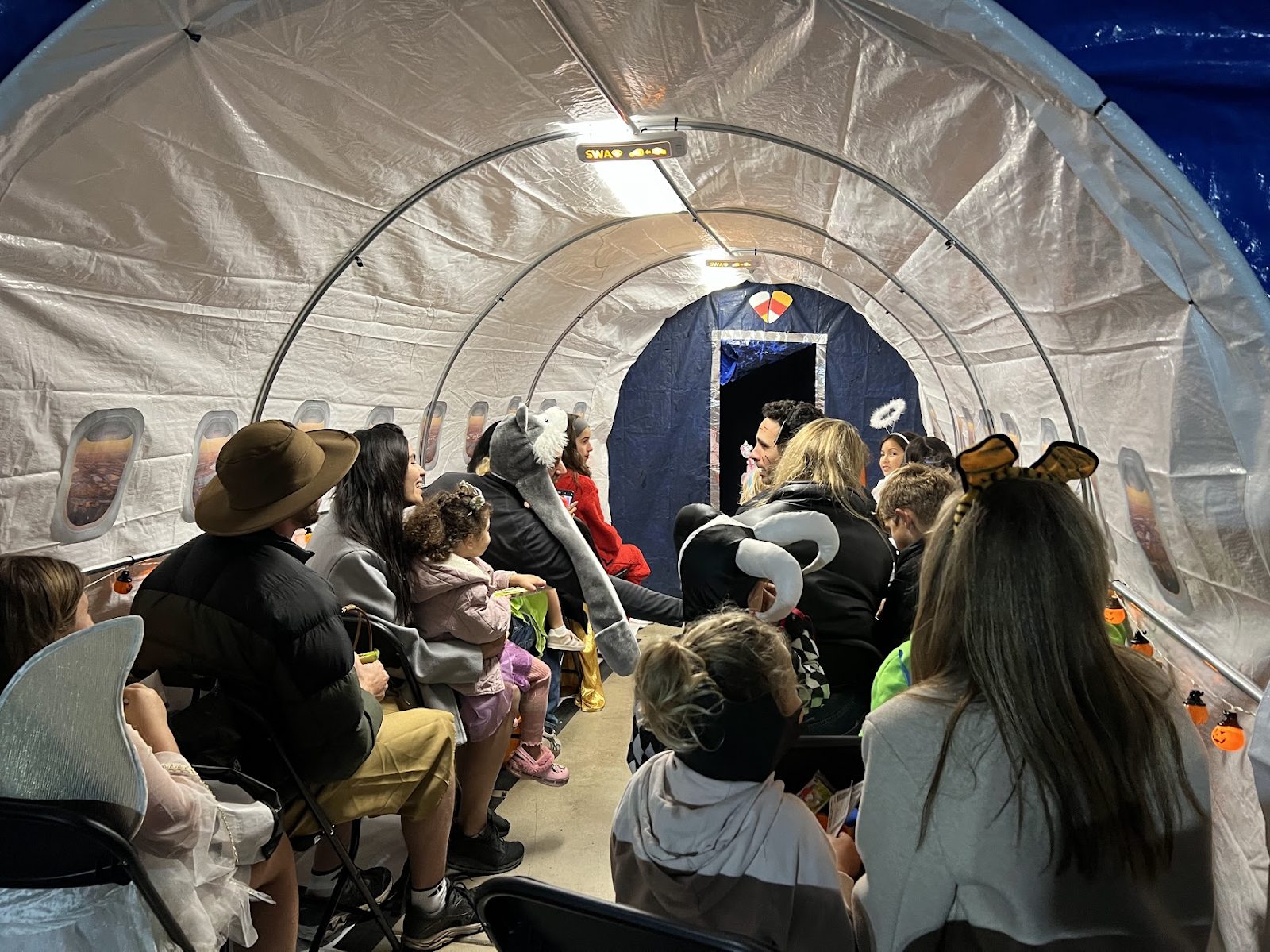
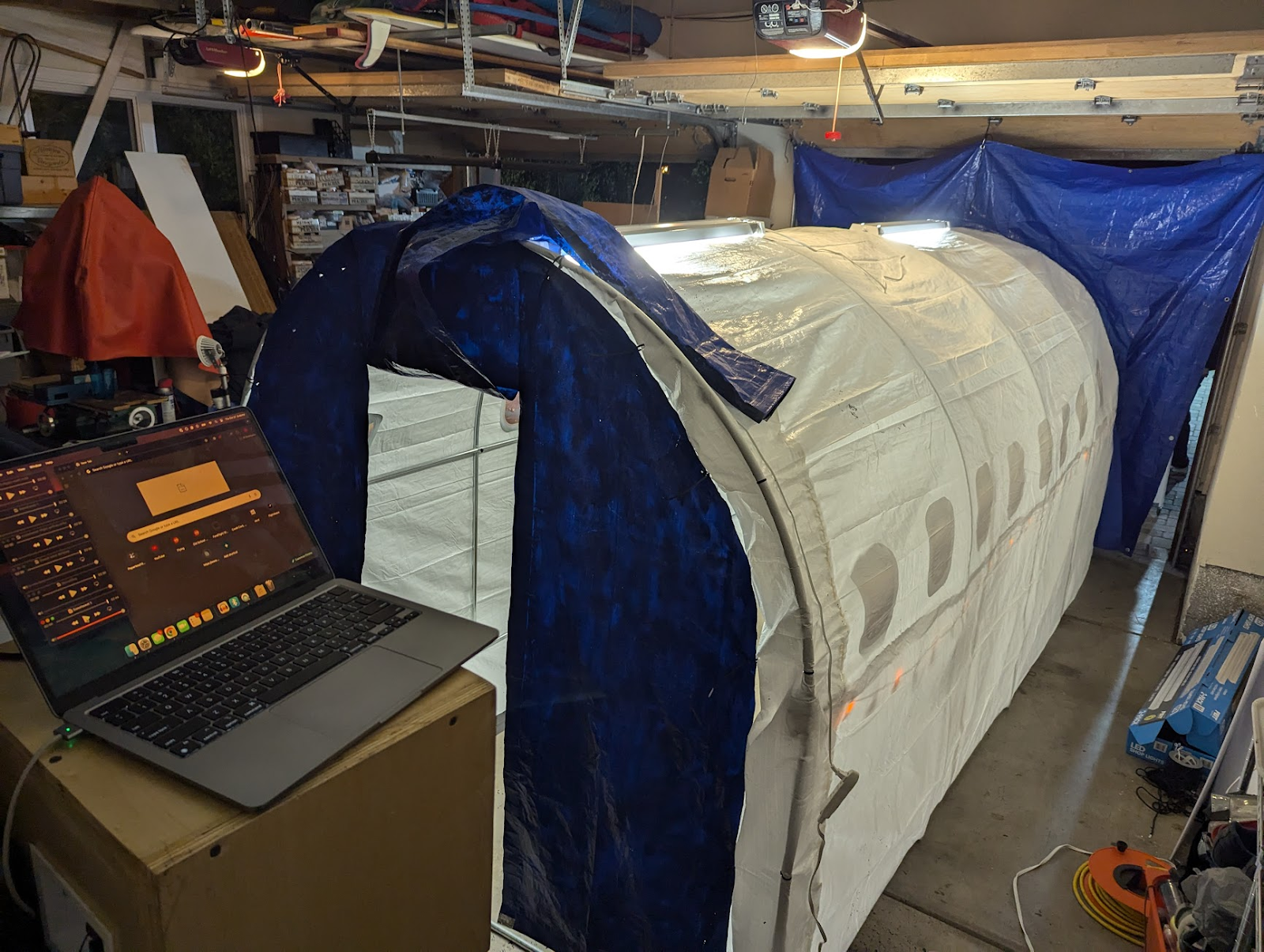
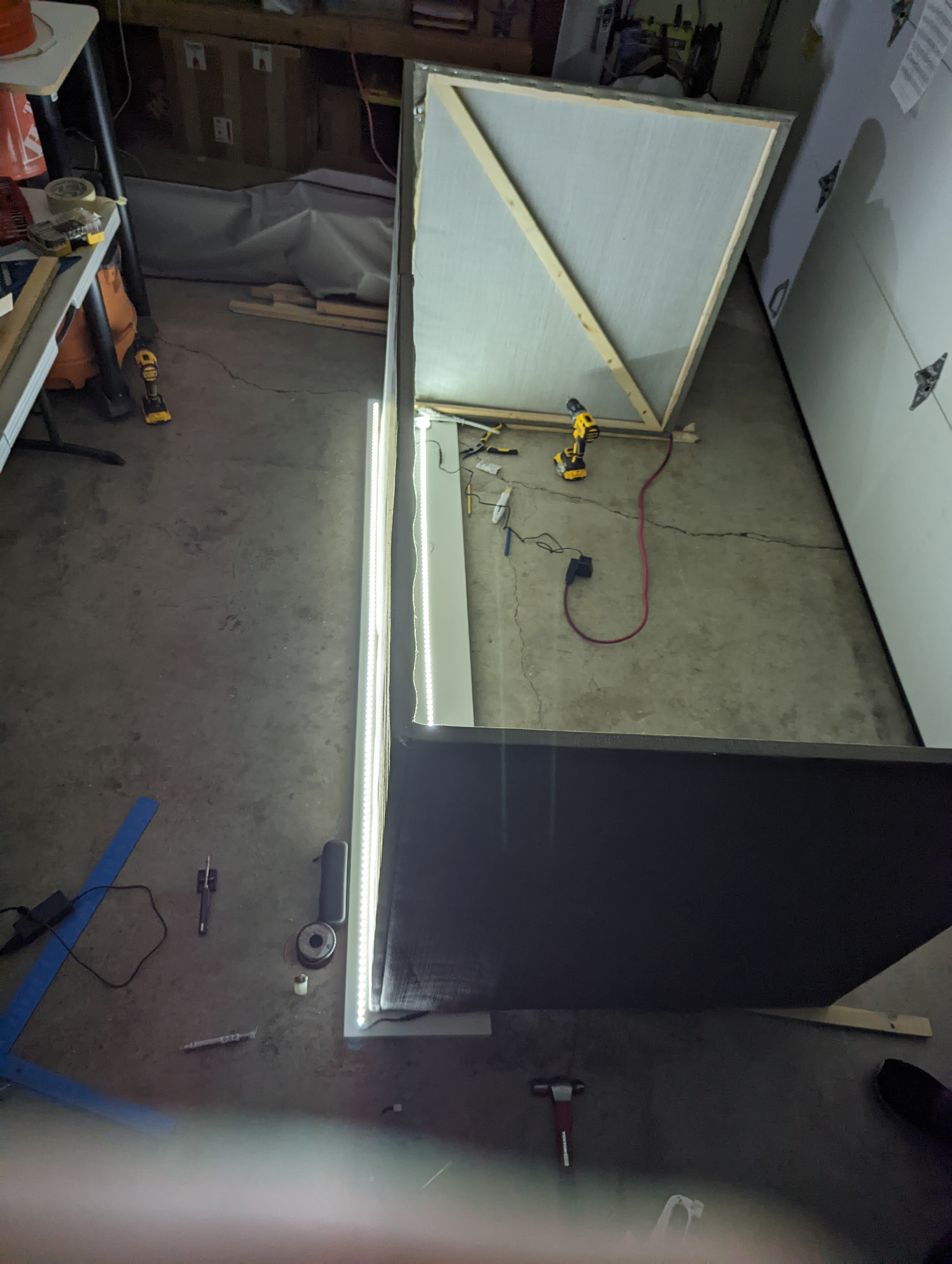
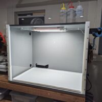
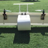
As luck would have it, a 15 foot greenhouse was inexpensive ($80) and just about the right size to fit these criteria, with the added bonus that the rounded top was strongly evocative of an airplane fuselage. During the weeks preceding Halloween, our team set about transforming the greenhouse into an airplane. The clear exterior plastic sheeting was replaced with a large white tarp, and paper windows were printed and attached to the inside of the fuselage with spray adhesive. A significant quantity of surprisingly affordable plastic folding chairs was installed and taped to the garage floor inside the fuselage to serve as seating.
As a stand-in for floor-level exit lighting on typical passenger aircraft, jack-o-lantern string lights were installed along the side of the fuselage (and were referred to during the safety briefing). Lighting for the inside of the fuselage was provided by two LED light fixtures that were adhered to the top of the arch, on the outside of the white tarp serving as the fuselage skin. The lights diffused remarkably well through the tarp, and really helped sell the aircraft interior with their rectangular silhouettes and daylight color temperature.
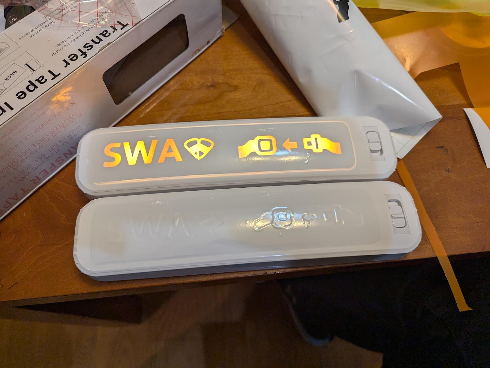
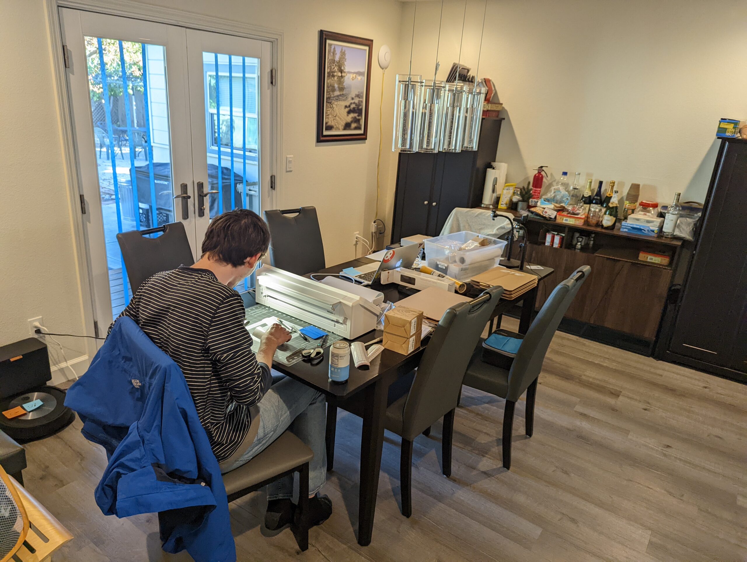
The night before halloween, one of our volunteers chanced upon a set of remote-controlled light bars in Target, and these were promptly transformed into remote-activated seatbelt signs for the interior of the aircraft with the help of the vinyl cutter (apparently, the trick to getting a good “seatbelt sign” effect is to use an orange binder divider as a colored diffuser, followed by black vinyl as a mask layer, followed by white vinyl as a top cover).
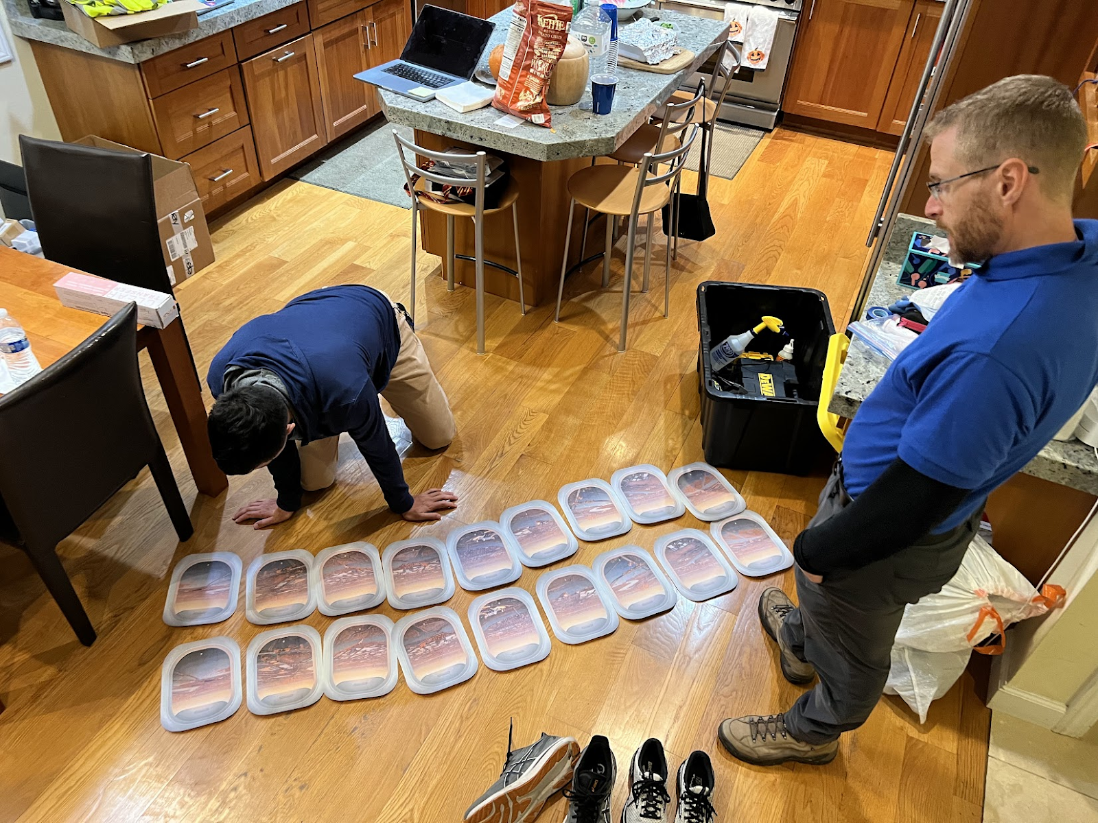
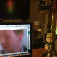
An aside about the windows: the scenery for the windows was pulled from a cell phone video taken out the window of an aircraft as it was landing. Subsequent frames of the video were used to create a unique perspective for each window, and then composited with a hand-drawn “window frame” in Affinity Designer to create a printable window for each row of the aircraft. The full row of windows was mirrored to create a different view for the other side of the aircraft. As a result, every window on the aircraft was actually a unique picture! This did lead to some confusion when I made the brilliant decision to not number the window printouts, and the entire pile of them was predictably dropped on the floor. Our volunteers spent at least fifteen minutes playing “spot the difference” with 18 unique picture cutouts to put them back in the right order.
To really sell the airplane experience, one of our volunteers crafted a series of audio files that included the pre-flight safety announcements as well as engine noise (takeoff / cruise / landing / reverse thrust) that were played over a speaker system in the garage.
During takeoff and landing, volunteers would slightly shake the outside of the fuselage to simulate vibrations. In addition to welcoming passengers onto the aircraft and telling them when the flight was over, our “pilot” (coincidentally, a real airline pilot), controlled the aircraft audio playback and seatbelt signs from the “cockpit”, a laptop in the garage.
Each flight had two volunteers working as flight attendants. The flight attendants performed a cabin check and safety briefing (with props) before takeoff, ran a snack service during cruise, and hid in the cockpit area (outside of passenger view) during takeoff and landing.
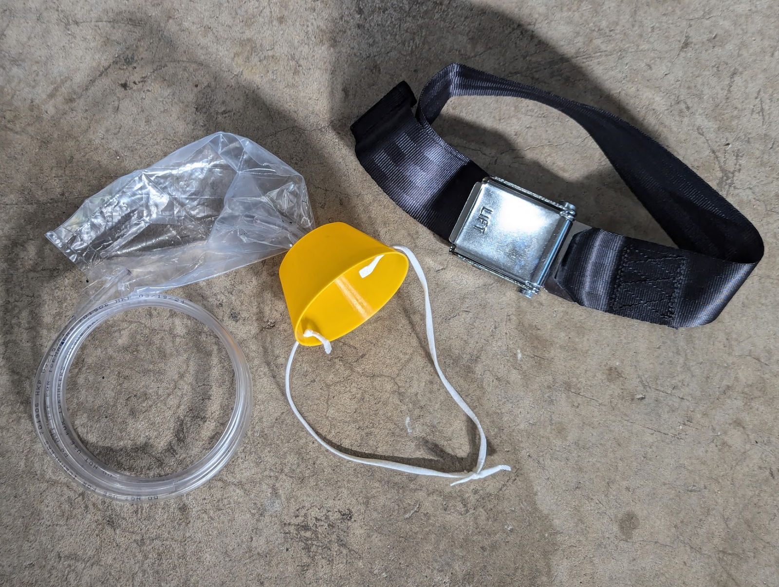
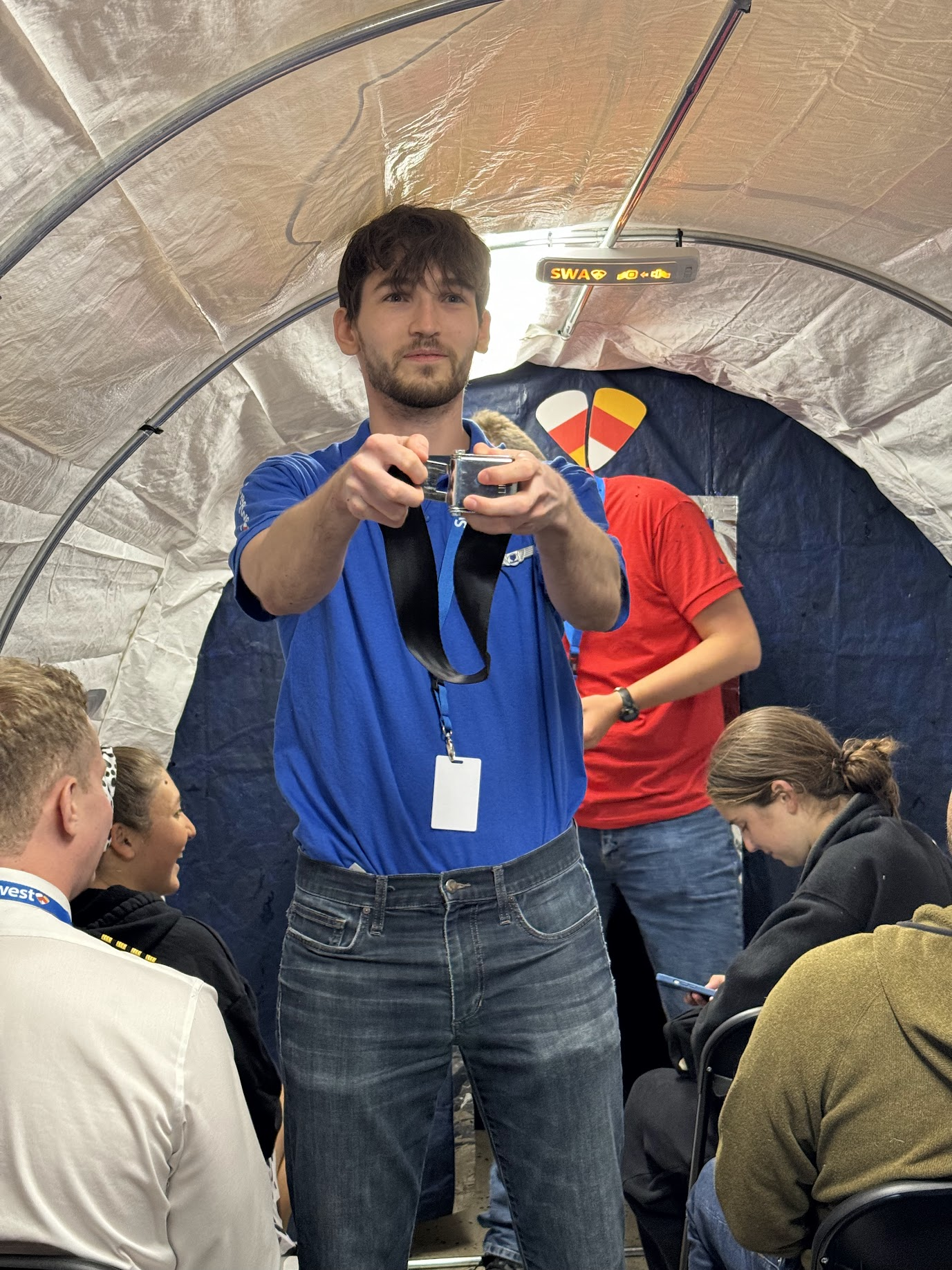
For the safety demonstration, we used a standard seatbelt extender to demonstrate safe buckling and unbuckling of seatbelts, and used an oxygen mask prop that we cobbled together from a 3D printed cup, some ear straps from a COVID-era N95, tubing from Home Depot, and a Ziploc bag.
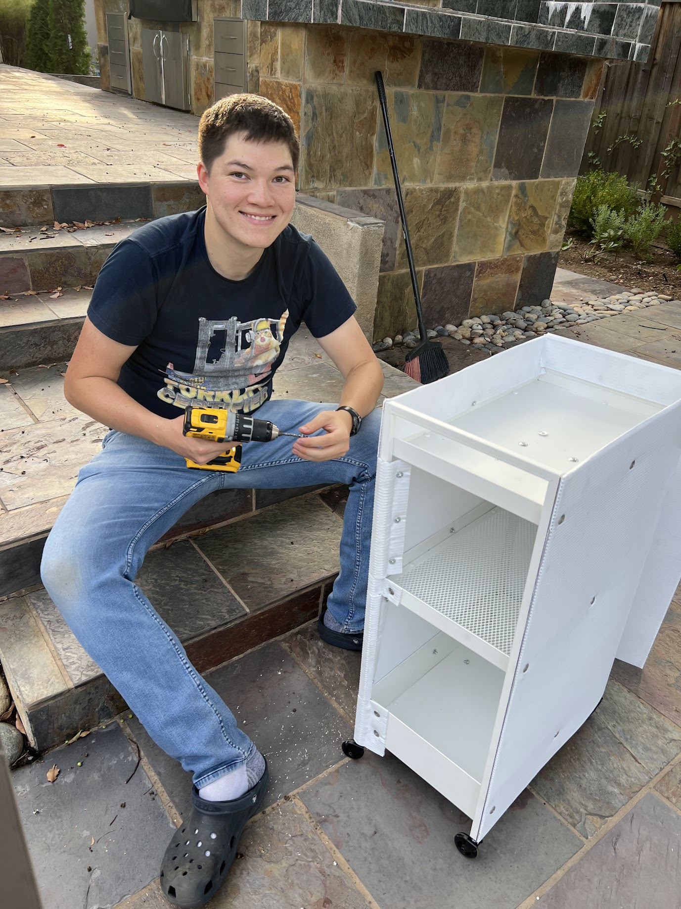
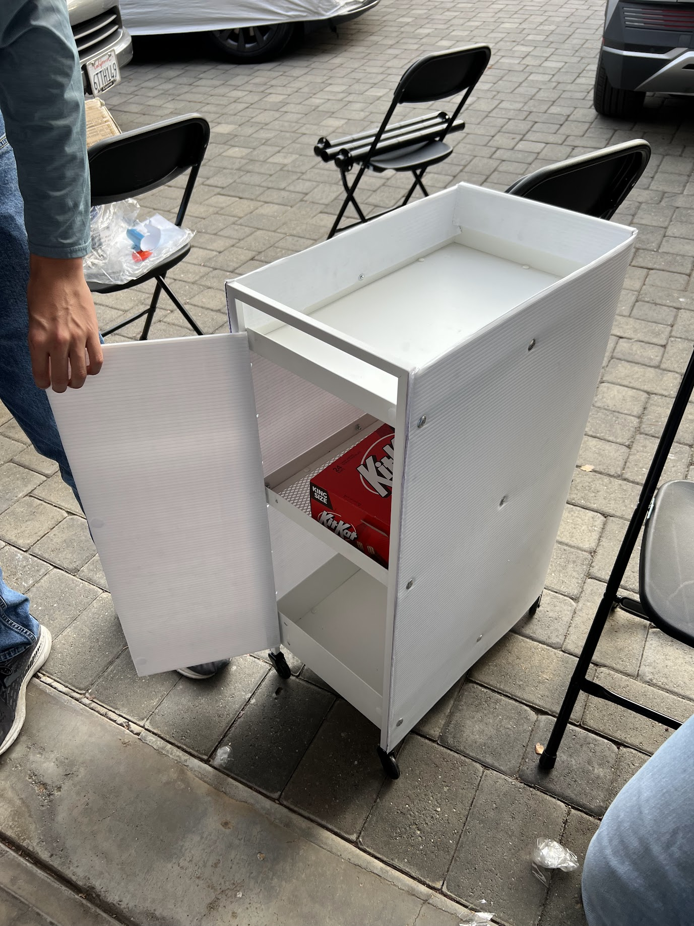
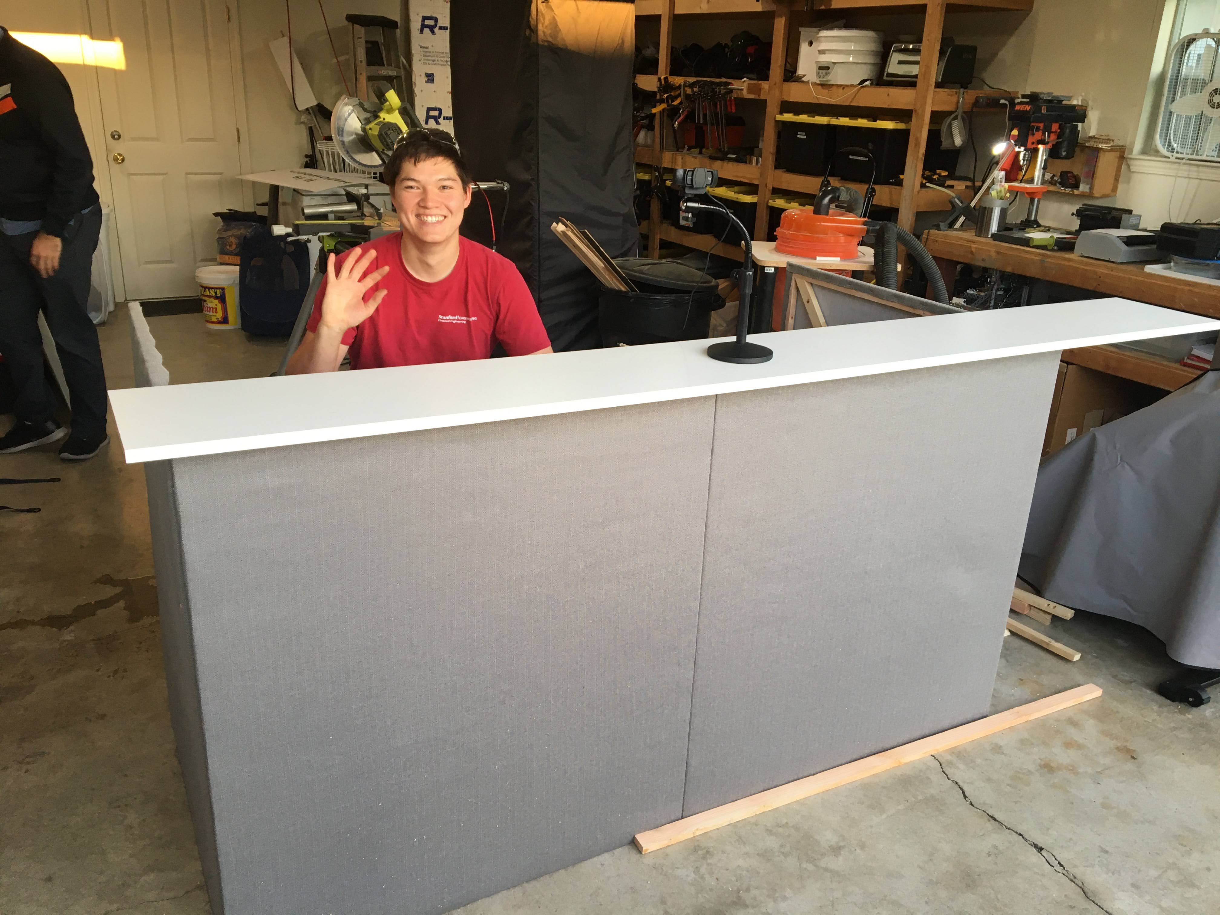
The snack cart utilized in the aircraft was a $30 cart from IKEA that we wrapped in a piece of white coroplast, fastened to the cart frame with aluminum pop rivets. Kids LOVED the snack cart–a highlight of Halloween night was hearing an audible reaction from the aircraft every time the flight attendants emerged from the forward bulkhead for candy service.
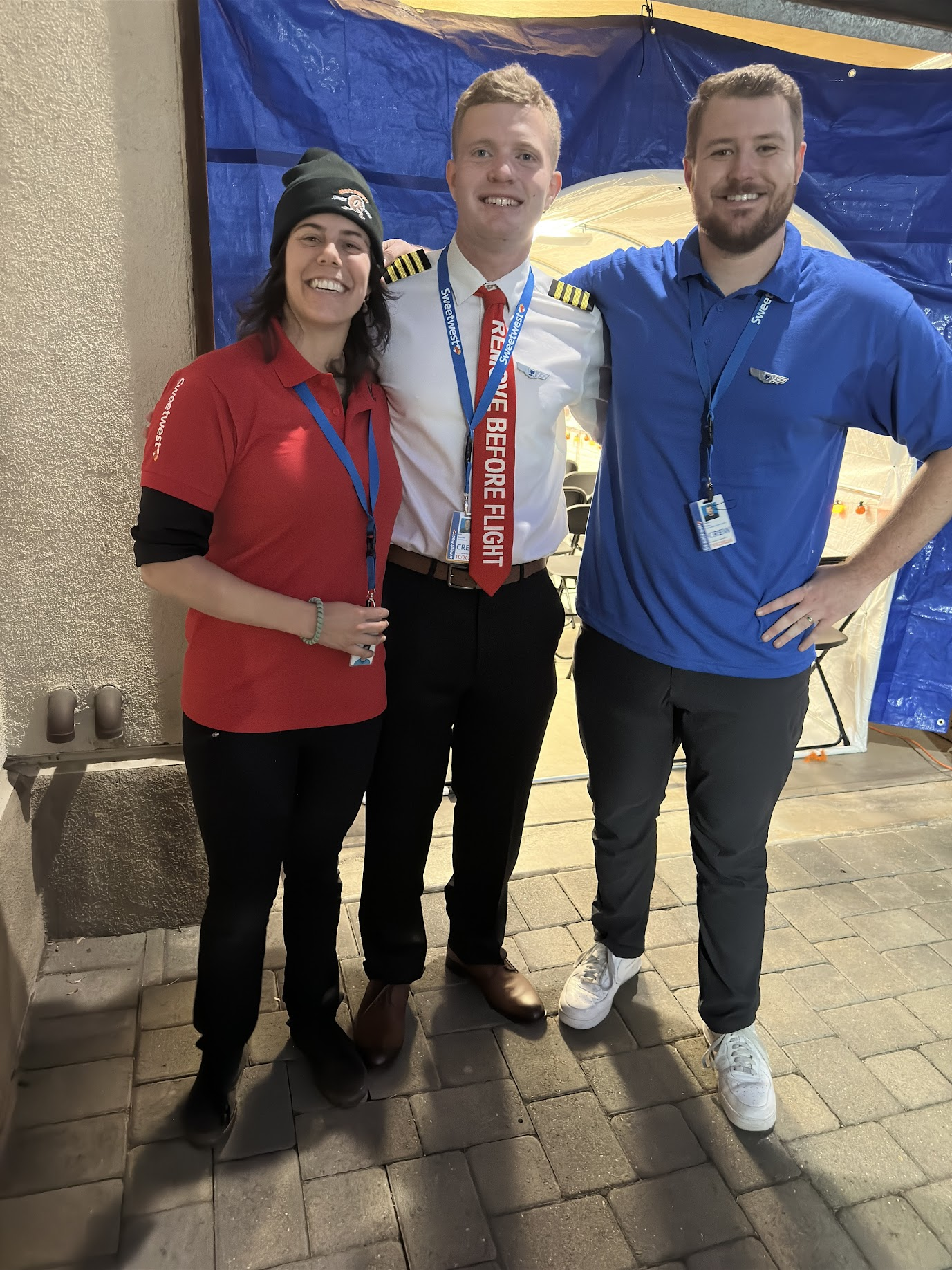
Costumes
No good Halloween whatchamacallit would be good without costumes! We had a record number of unique costumes for our Sweetwest Airlines event.
Pilot
Ramp Agent
Maintenance Crew
Flight Attendant (fancy)
Flight Attendant (casual)
Gate Agent
Ticket Agent
TSA Officer
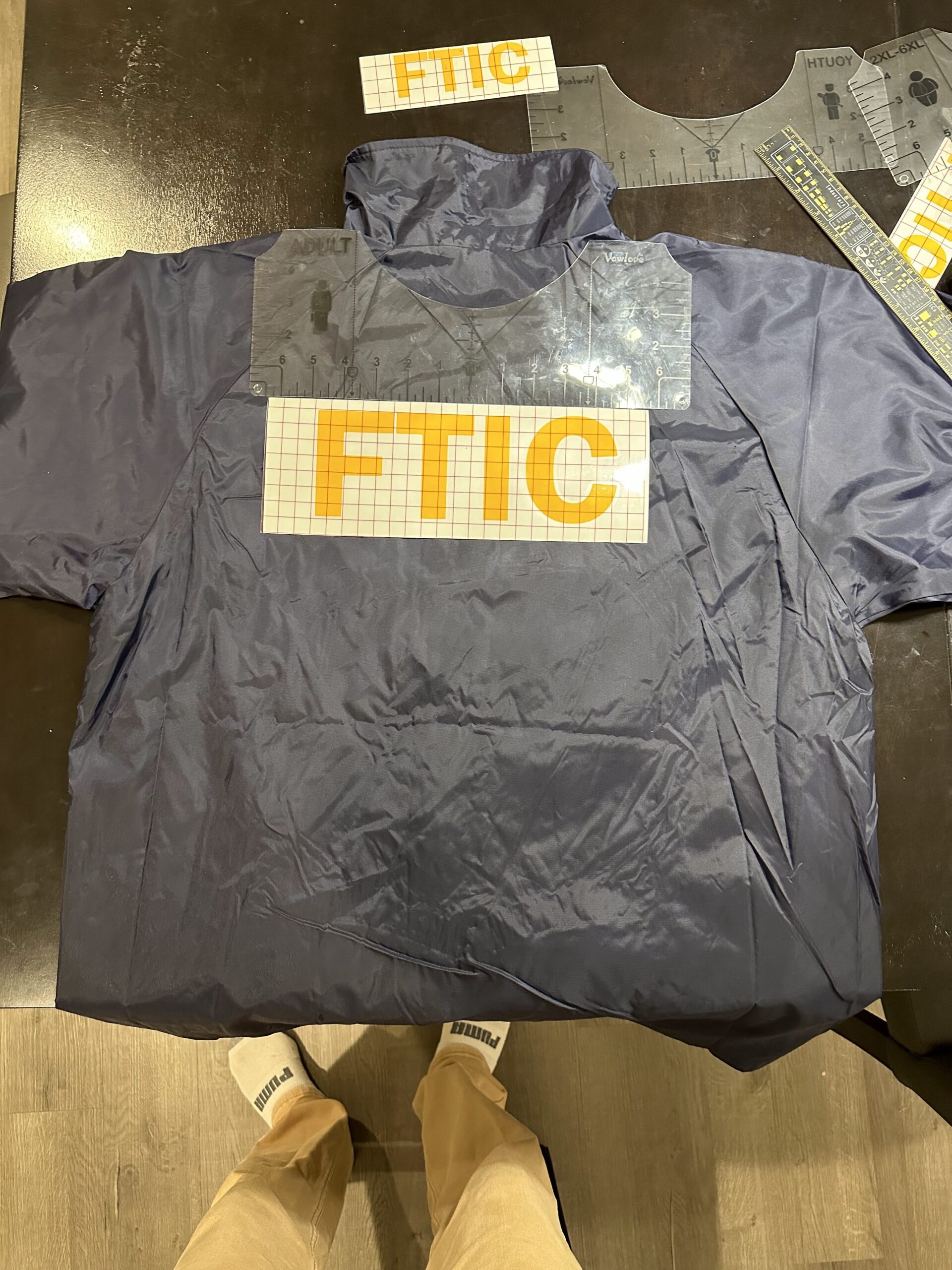
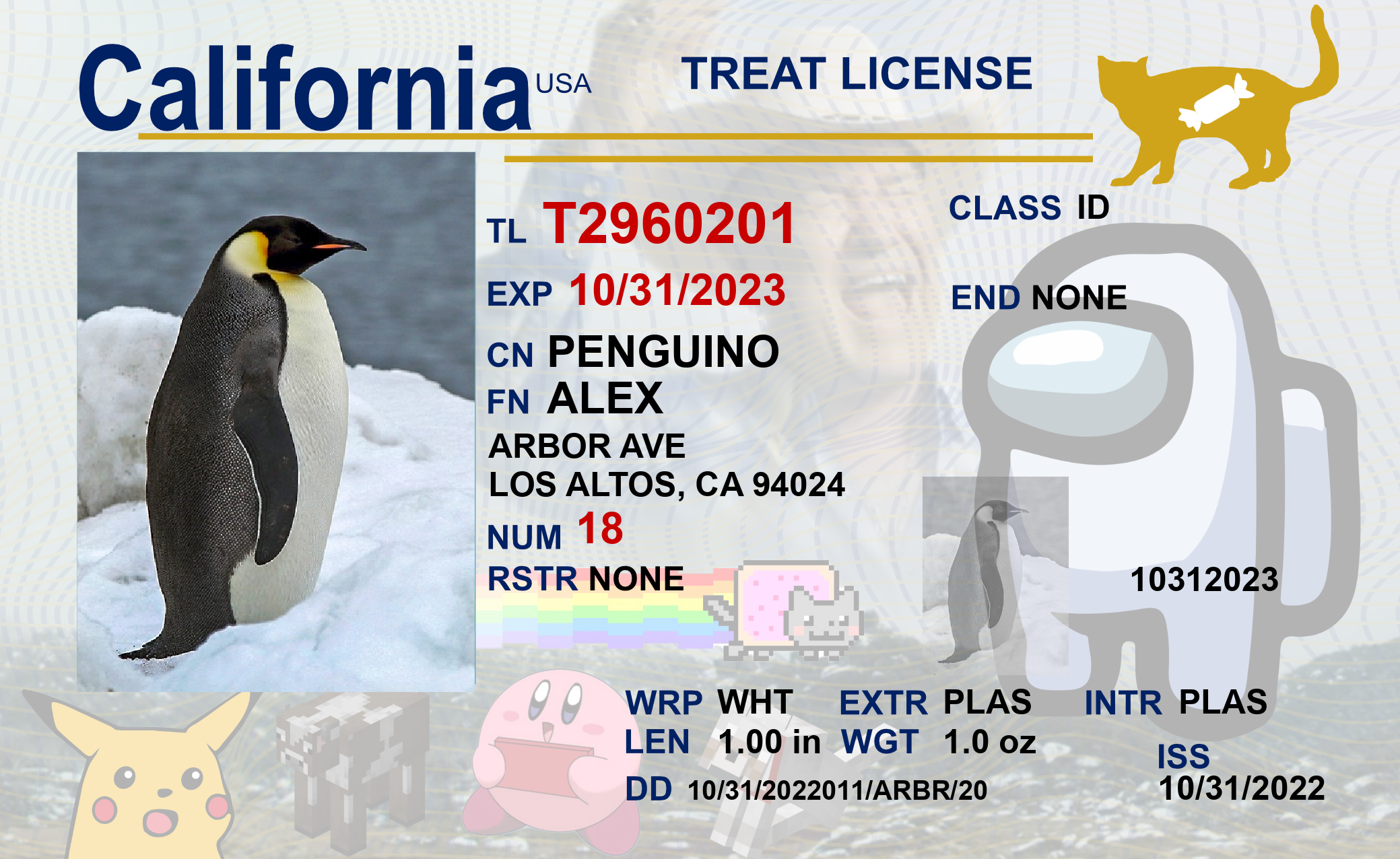
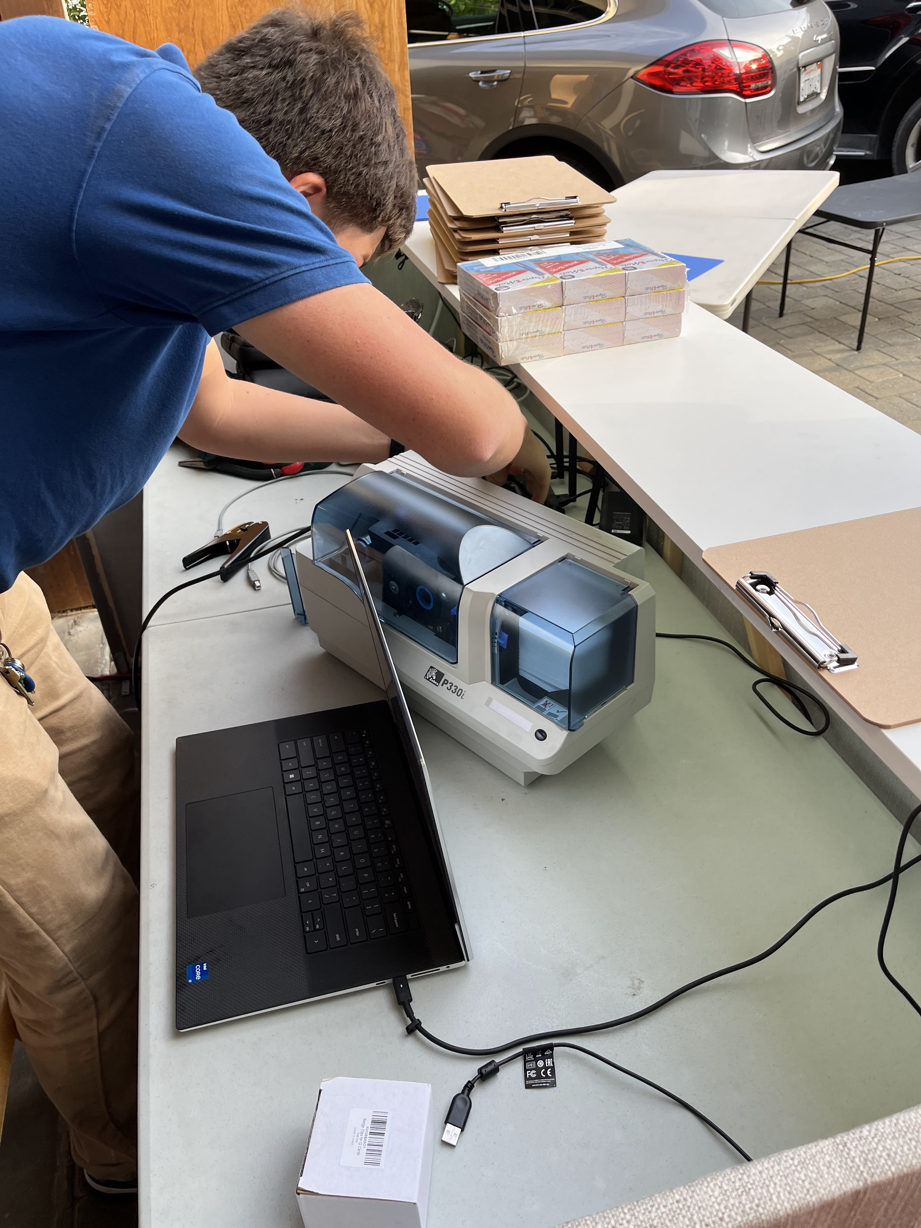
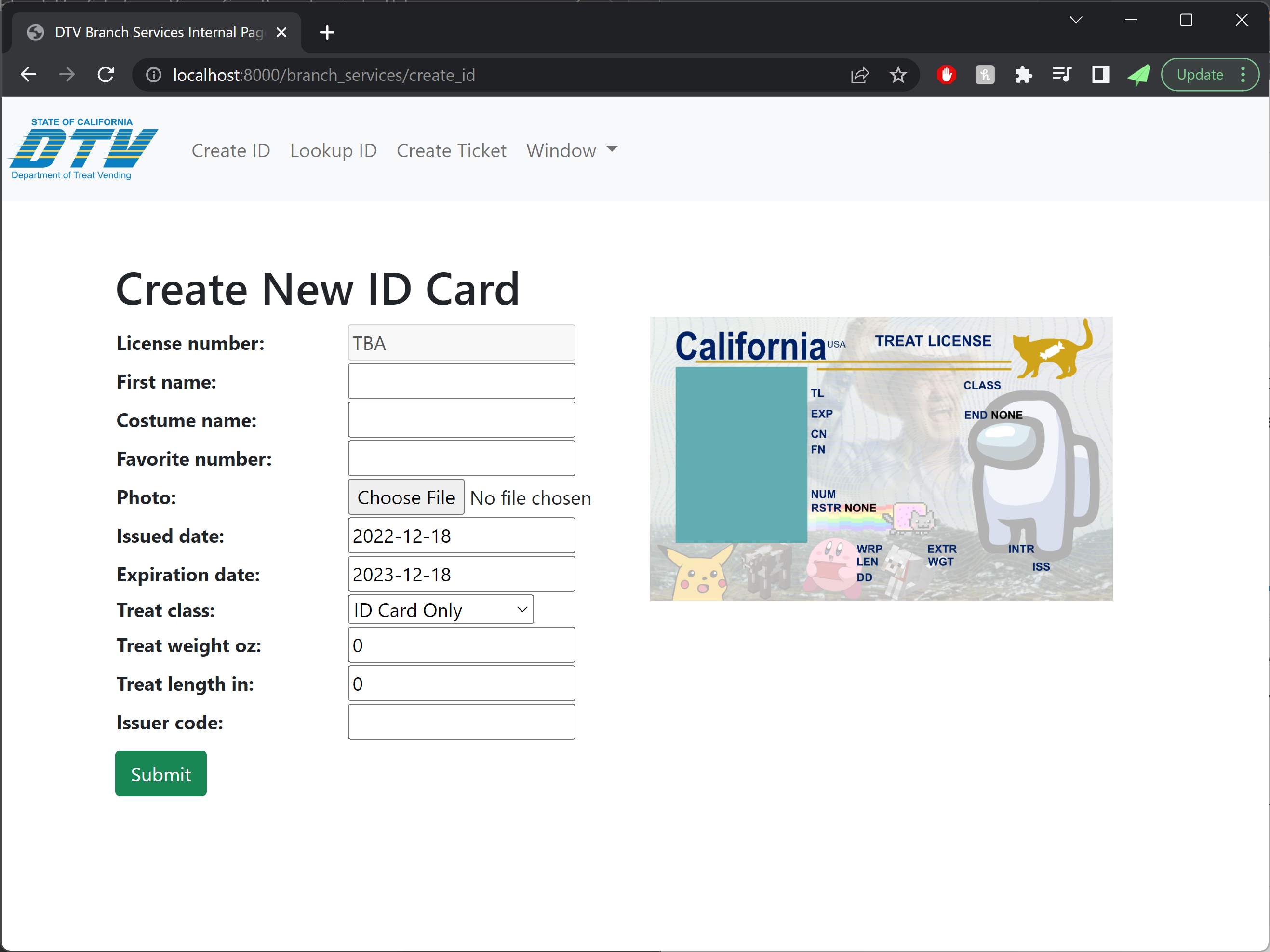
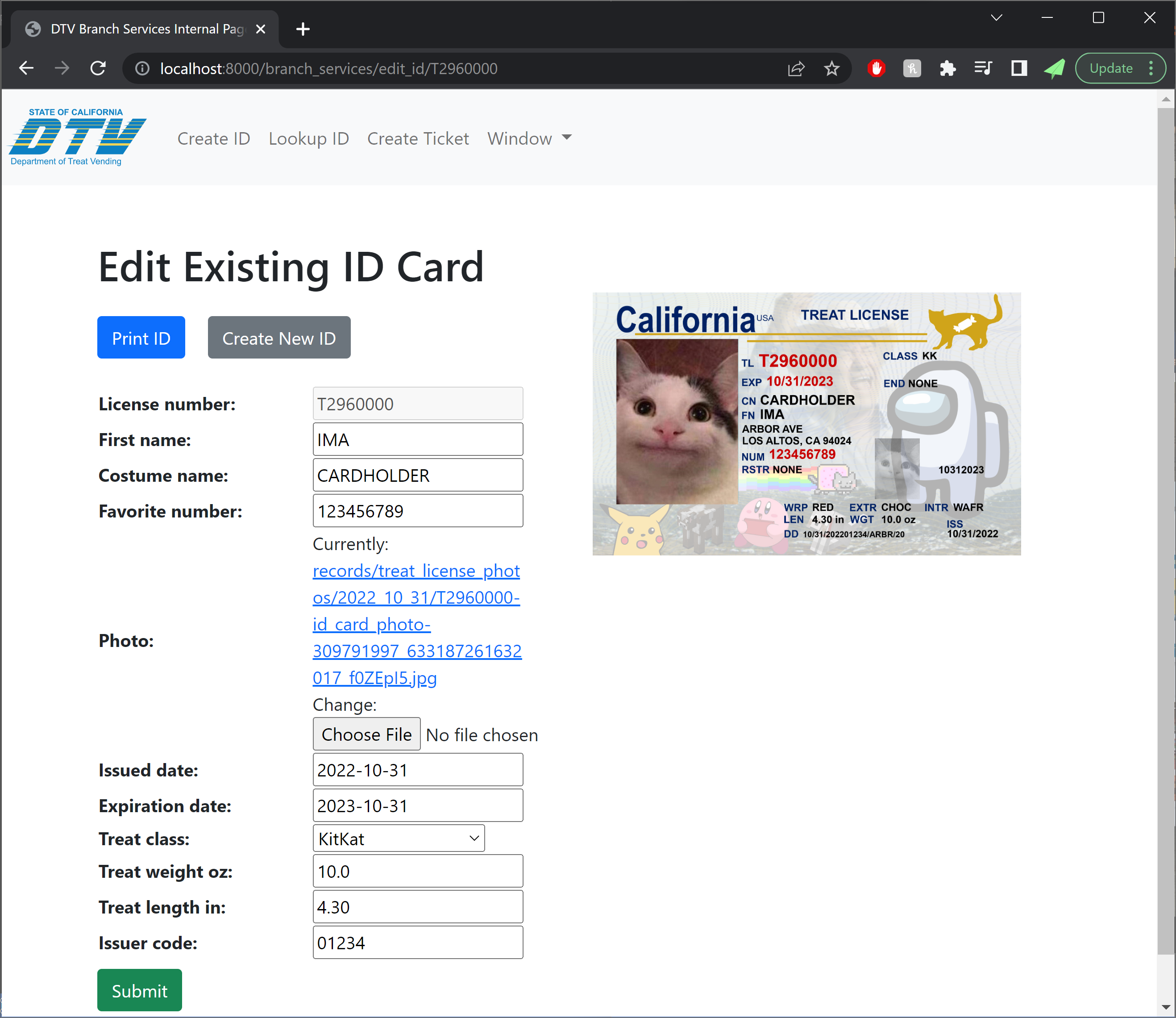
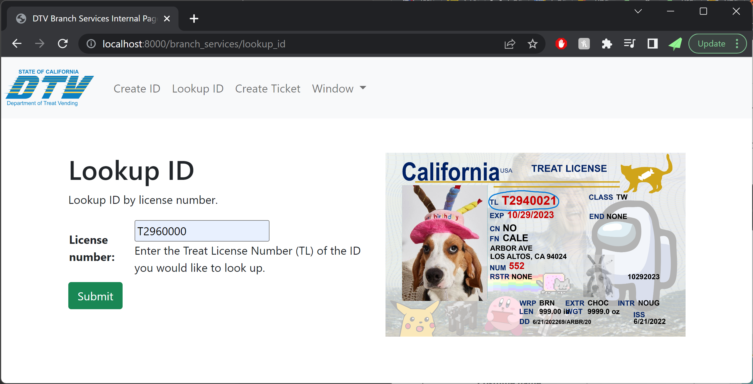
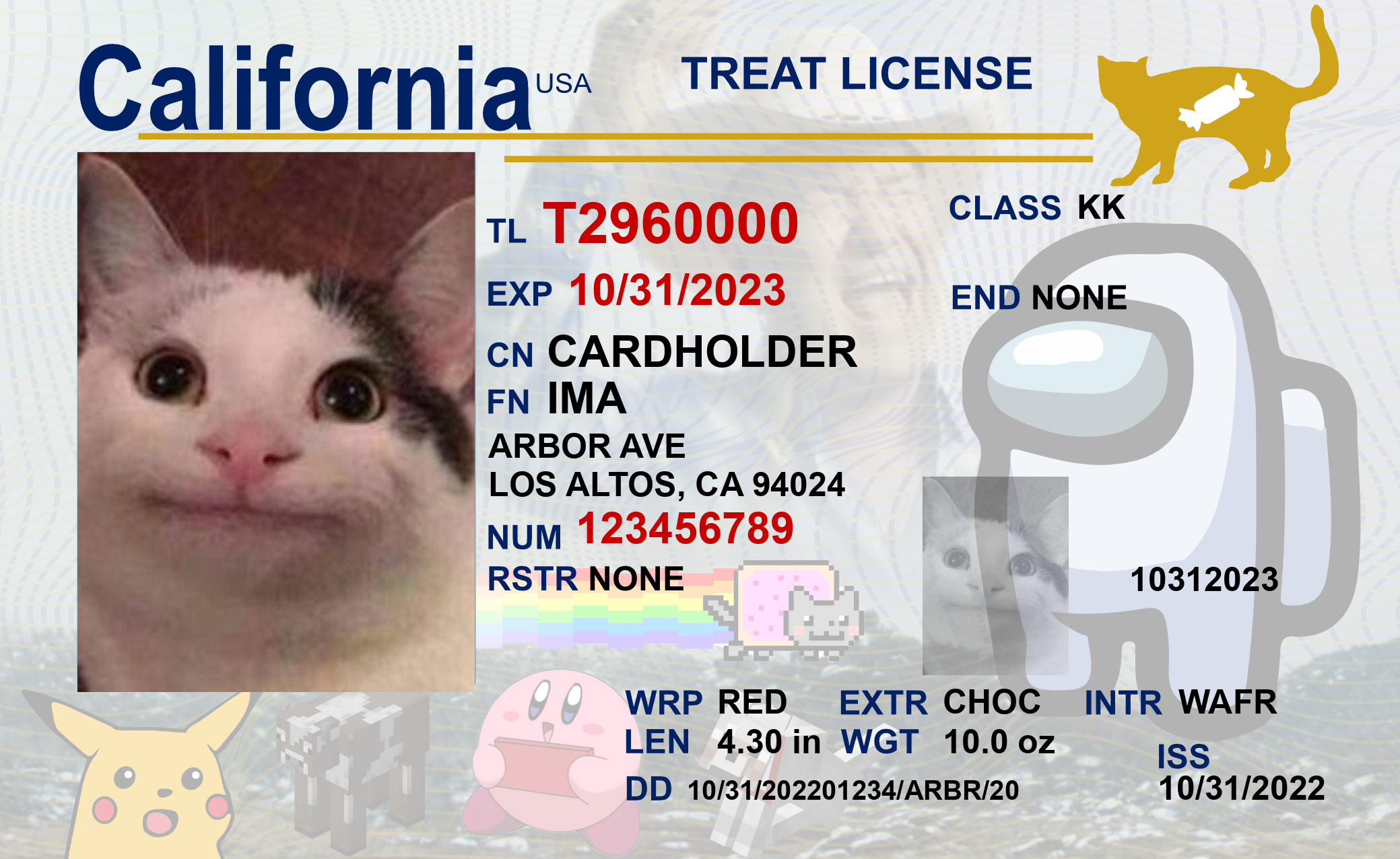
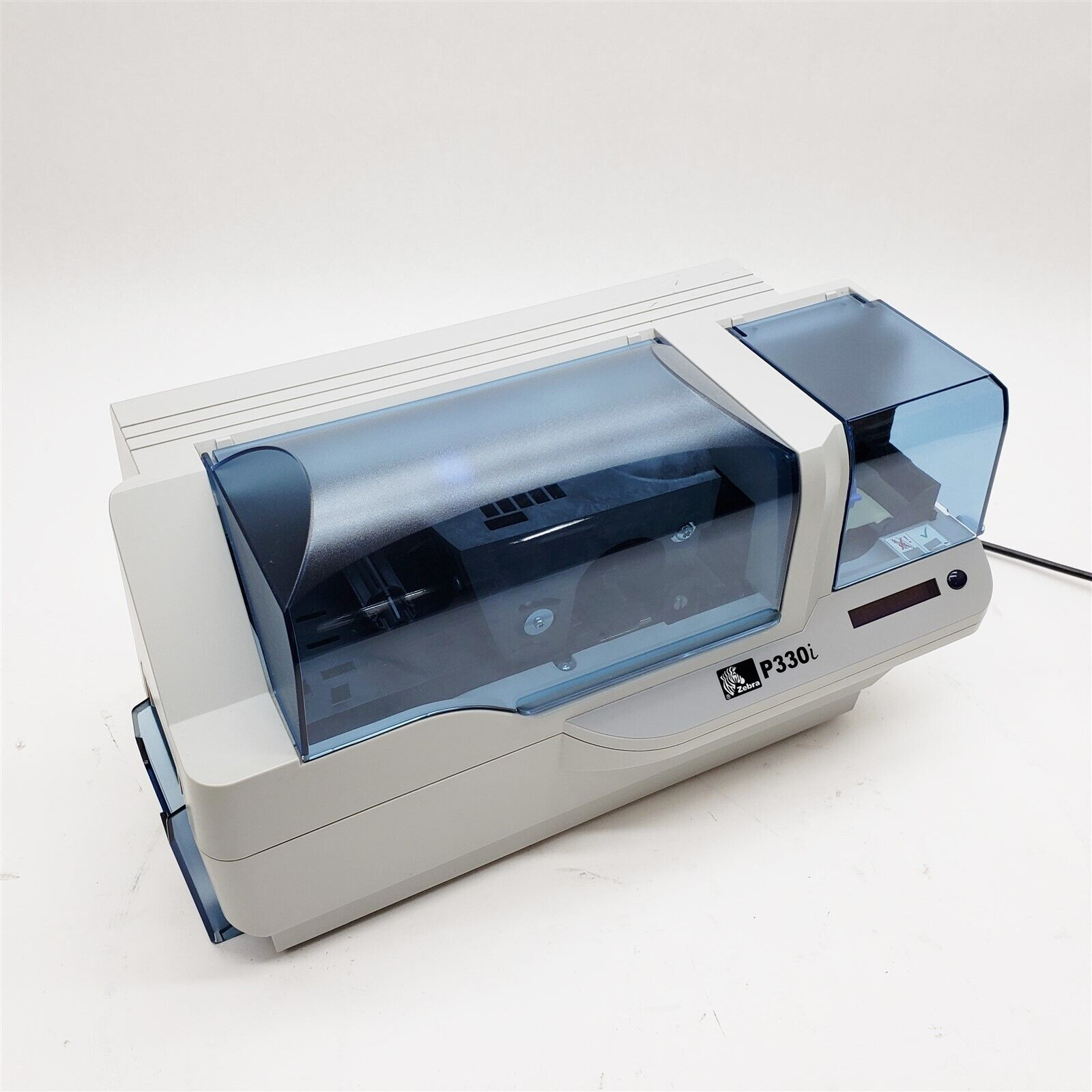
Each costume came with its own ID card, which we printed off using our ID card printer from previous years.
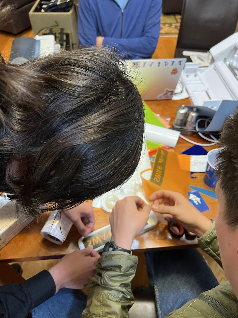
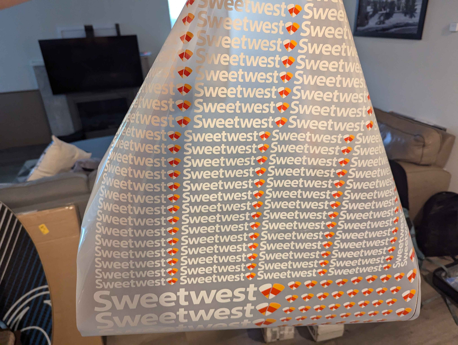
We handcrafted custom Sweetwest branded lanyards using some blue lanyard blanks off of Amazon and some direct transfer film prints of the Sweetwest Airlines logo, which were applied via a heat press. All branding on reflective vests, polo shirts, and maintenance coveralls were applied in the same fashion. The direct transfer film proved to be super affordable and a huge timesaver. We paid just $30 for a gang sheet of all the logos we needed for the entire costume, and didn’t spend more than a few hours cutting the logos out and applying them to blanks with the heat press! This saved probably 7-8 person-hours of labor that would have otherwise been spent weeding vinyl cutouts and compositing different vinyl parts together to form multi-colored logos.
IT Systems
IT Systems: Background
The main goal of any software we add to our Halloween costumes is to make the experience come alive, both in terms of functionality and aesthetics.
From the initial brainstorming phase of this year’s concept, it was clear that successful execution would require central tracking of tickets as a bare minimum. After encountering technical difficulties the previous Halloween, one of our main goals was ensuring that the infrastructure we created this year would be extremely robust and reliable. As the idea expanded, so did our technical aspirations, increasing the complexity of the overall project.
We initially defined two main flows to build:
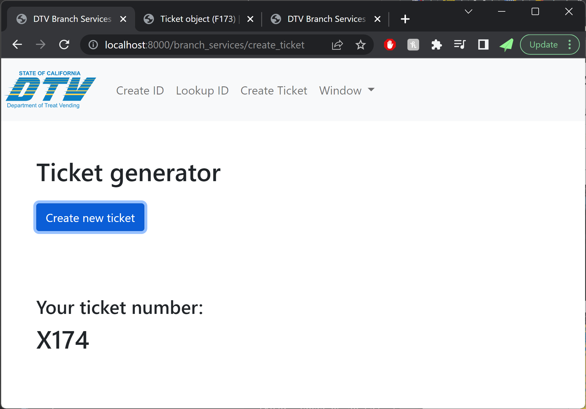
Trick-or-treaters should be able to get a printed boarding pass.
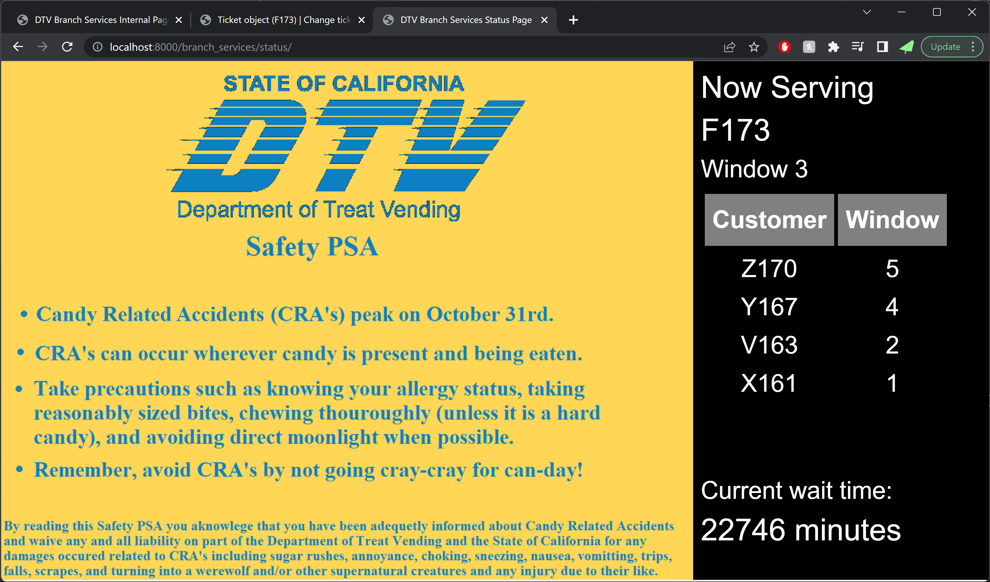
Volunteer team members and trick-or-treaters should be able to see flight information (time and status).
A lot of the pieces that would make it into the final costume were not there yet — for example, we didn’t talk explicitly about scanning barcodes, and we certainly didn’t talk about using PDF417 (the format real boarding passes use) to actually use scanned boarding pass information to mark passengers as boarded.
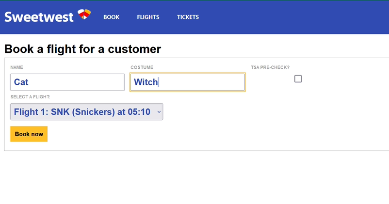
The initial draft of the website came together quickly, so we looked to the Southwest Airlines website for…inspiration in our styling and design of the UX. Although these screens would never be used by trick-or-treaters, they were very likely to be seen in passing, used by our volunteers.
A screenshot of the “ticket booking” screen on an early version of the website, with styling. We felt very inspired.
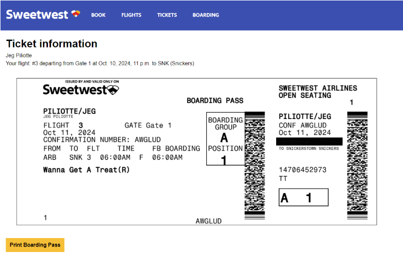
Next on the plate was connecting the data from booking to a printable, dynamically-generated boarding pass. We were able to connect to printers on the same network as the site, and planned to repeat this setup (by creating a special costume network) on the night of Halloween. Our design of the boarding passes paid close attention to detail, and actually encoded relevant data in the boarding pass barcode format (PDF417). This of course begged the question: what if boarding passes could actually be scanned by volunteers, and allow gate agents to call out missing or out-of-order trick-or-treaters?
An example boarding pass.
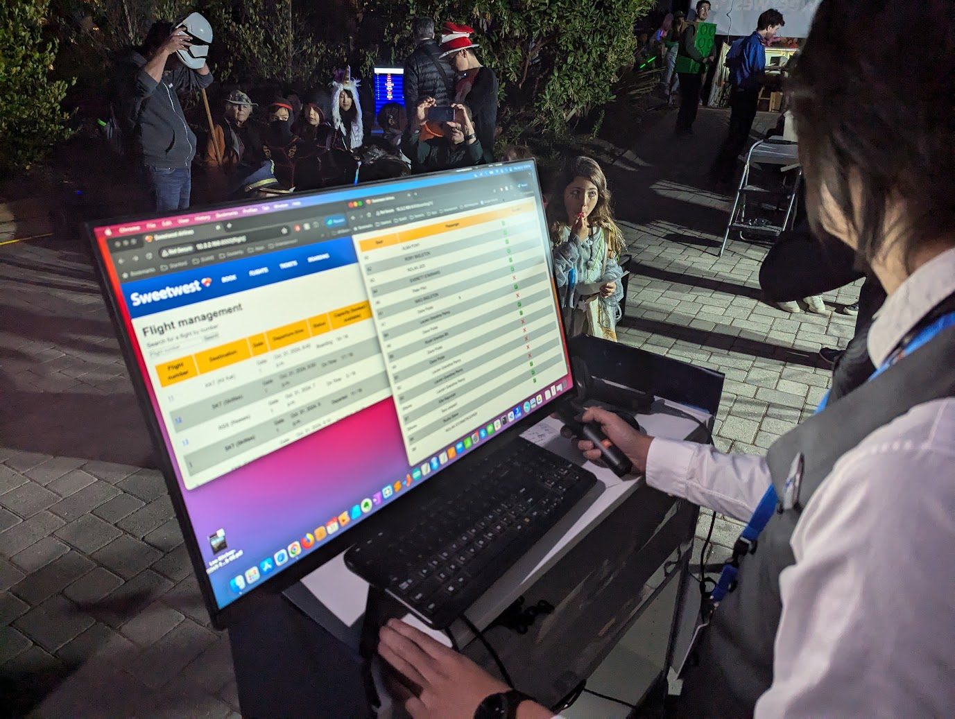
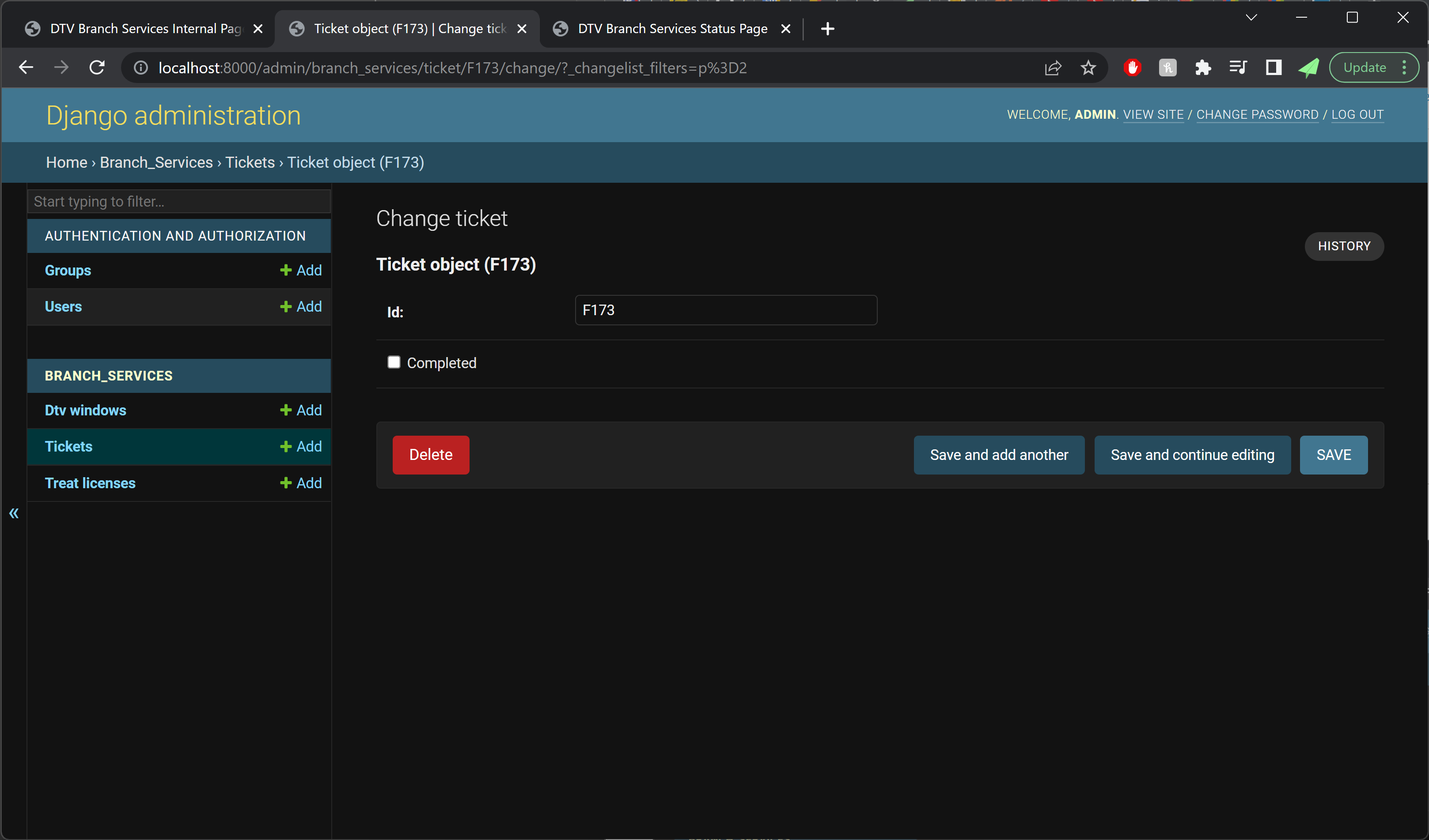
Over the last week prior to Halloween, we added a flurry of boarding and gate-agent related features. The final product allowed gate agents to scan continuously without having to use any mouse or keyboard input, and it also surfaced very specific error messages to support the agent in performatively berating trick-or-treaters for whatever had caused their ticket to be rejected.
IT Systems: Technical Details
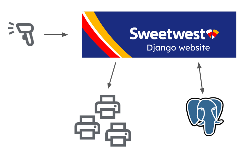
The website was built in Django, with some simple vanilla TypeScript for any frontend pages requiring dynamic behavior. Since the project used Docker Compose, it was straightforward to add a Postgres container as our database. Label printers on the same network as the website deployment were sent boarding pass print jobs, and the ordinary text output from a barcode scanner was used by the “gate agent” volunteer to track “passenger” boarding.
A diagram showing a very high-level overview of hardware and software infrastructure
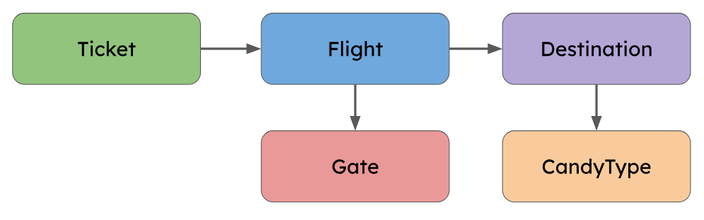
The data model was designed fairly early on to be accommodating of many potential future changes. Because of this the final model was somewhat over-normalized for the actual night-of-Halloween demands.
For example, the initial schema included a “Gate” model, which would allow flights to be mapped to any number of different gates. However, since our final prop layout only included one boarding area, we only ever needed to define a single gate, making the Gate model superfluous.
A diagram of the data model used in this project
IT Systems: Night of Halloween
On Halloween night, we had a much more capable system than we had initially planned for. So of course it was time to introduce a bunch of last-minute feature requests that violated fundamental assumptions of the system!
About two hours before showtime, we got a new (huge, schema-upending) feature request: “we need to add standby tickets.” We had previously gone back-and-forth about how best to handle no-shows, and decided to just fly without those passengers. Adding standby would be an excellent fix, but would require major changes to the booking, boarding, and flight display pages, so we had previously written it off as too much work. With minutes to spare, we converted our existing system into one that was compatible with standby, involving a lot of big changes:
The largely unused TSA pre-check database field was renamed and modified to capture standby info
Booking was updated to ignore standby tickets
The boarding pass generation was updated to indicate standby in the boarding position field
Boarding was updated to let standby tickets be scanned in and counted as part of the flight capacity
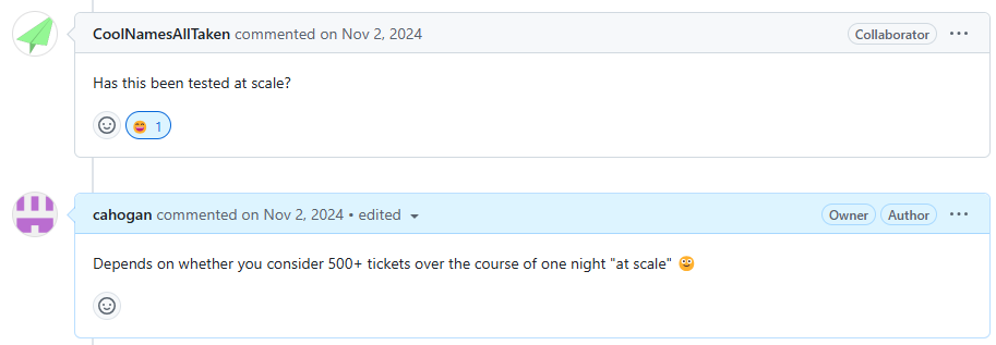
In either a minor miracle or a product of our clean and robust codebase, the standby feature worked perfectly at launch!
Meaningful review comments on the standby code from an esteemed collaborator.
Even the best-planned project doesn’t always escape its first use unscathed, and over the course of the night we made a few more changes for balance on the fly (pun not intended):
Reduced boarding time to 7 mins from 15 mins (trick-or-treaters were waiting in the gate area for longer than was fun)
Added more info about boarding to the gate agent page (gate agents needed to stay informed about delays to takeoff time)
Hid departed flights from the flight display page (it was already difficult to get across the concept of booking a ticket for a flight, and having departed flights on there just confused guests further)
IT Systems: Terminal Audio
For this part of the project, we started with a list of critical features that the audio system really should have in order to provide the best experience. Last year we found that a modest single 65W loudspeaker was not really sufficient to cover the full driveway area, so we decided to upgrade to two iOn Pathfinder 320 portable speakers. These each have 3x the power, and take both bluetooth and aux input to help leave our connectivity options open. For inputs, our plan involved announcements from both the attendant at the boarding counter, interspersed with other miscellaneous announcements by a staff member at a variety of locations, so we settled on the “JBL Wireless Microphone Set” (that’s literally the part number). These choices ended up performing quite well, with plenty of volume from the speakers, and convenient announcements from anywhere with the mics.
To tie the inputs and outputs together, we started by making a list of critical features that the audio mixer system really should have in order to provide the best experience:
Continuously playing background ambiance (airport lobby music)
Slightly obnoxious attention chime right before an announcement
Live microphone audio with acceptably low latency
Auto-ducking the ambiance when the microphone input is active
Dedicated hardware for performing these types of audio processing functions does exist, but brief research suggested that they start at roughly 4 figures, so we decided to try rolling our own solution. Music producers commonly use a type of software called a DAW (digital audio workstation), and many of these also come with tools for giving a live performance, including real time multi-channel mixing with a huge variety of software effects.
One of the big challenges with doing anything related to live audio on a computer is latency, and generally producers will use an Apple laptop because a huge amount of development effort has been put into making audio latency on MacOS as low as possible. However, Linux is able to achieve a comparable level of performance with the right drivers, though perhaps at the cost of increased effort to set it up. For this project we are very lucky to have the excellent 60 day free trial of REAPER available, which supports every major OS including even Raspbian.
As with any other project involving Linux, there are some specific details that were very important to achieving the functionality we wanted. Linux has several different audio drivers for specific use-cases, and the general purpose one is called pulse-audio. This works very well for all of the usual tasks like watching youtube or having a telecom, but doesn’t have the best performance with regards to latency. This is where REAPER will instead prefer the ALSA driver, which is optimized to get the best performance out of your audio hardware, but is much less compatible with various software than pulse-audio. For this project we wanted to mix audio from both the background ambiance youtube playlist, and the low-latency live microphone input, and this required a creative solution to bridge the gap between the two sound drivers.
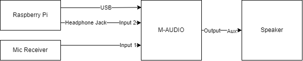
Starting with the lobby music ambiance, it was easiest to play it on youtube in the browser, which pipes it to one of the system outputs using pulse-audio. It might be possible to use some complex software solution to loop that back and redirect it as an ALSA driver input, but it was far simpler to just add another audio input to the system and loop it back in hardware externally. It is very important to note that for multiple inputs ALSA requires them all to be part of the same device, otherwise there are some obscure sampling clock misalignment issues that were not worth digging into at the time. To make this work, it is most convenient to buy a USB audio interface with multiple inputs, and the M-Audio M-Track Duo was the cheapest reasonably functional option for this.
With that figured out, our system ended up looking something like this:
After some testing, we found that the speakers had a lot of latency when connecting over bluetooth, so we hardwired them with an aux cable splitter from the audio interface output. Also the raspberry pi 4 that was originally used had some occasional lag and stutters, so we swapped it with an Intel NUC with Ubuntu on it and everything worked great.
The setup in reaper is a bit contrived, but here is an overview of each channel:
Channel 1: This is set to be a mono input, and receives from input 1 of the audio interface, which is what the microphone receiver is plugged into. Raw audio directly from the microphones shows up here.
This channel is configured to send to channel 3, and to the master channel.
This channel also has compression plus high- and low-pass filters to remove the top and bottom frequencies, for better approximation of an airport PA system
Channel 2: This is set to be a mono input, and receives from input 2 of the audio interface, which is what the headphone jack of the NUC is plugged into. Audio from our ambient music playlist shows up here.
This channel sends directly to the master channel
This channel has a gate plugin on it with a very specific configuration. First, the detector input is set to auxiliary inputs (which are forwarded from channel 3 below), and the Invert Gate option is selected. Then, Send midi on open/close is selected, for controlling the airport chime.
This channel also forwards only its midi outputs to channel 4
Channel 3: Placeholder channel to add extra effects for adjusting the sound gate activation.
This channel has a reverb plugin to extend the duration of audio it receives from channel 1, since the gate plugin has a maximum hold duration of 1000ms, which is a bit short for this application.
This channel also sends track 1/2 of its audio to the auxiliary input (track 3/4) of channel 2, for use in the gate plugin as the trigger source
This channel specifically does NOT send to the master channel, as the output is only intended for the gate plugin
Channel 4: This just has an instance of ReaSamplOmatic5000 on it that is configured to play the airport chime sound clip once on any midi note activation, sending straight to the master channel.
This describes the configuration in theory, though there were several undocumented tweaks made in production to make things run smoother. The parts that I remember:
Some inexplicable hum was showing up on the microphone input, so one of the team members figured out how to use the ReaFir FFT plugin to build a noise profile of the hum and then subtract it from the input, which worked very well.
There was some issue with the channel 3 gate trigger extension technique, and eventually we just disabled the reverb and somehow things worked (we’re still not sure why).
Conclusion
This year’s Halloween costume was by far our craziest idea yet, and it was absolutely magical to watch everything everything come together thanks to the efforts of our (largest so far) team of dedicated volunteers. We handed out over 400 full size candy bars to passengers across 25 scheduled flights, and it took a few hundred hours of coding, gluing, spray painting, heat pressing, crafting, and debugging to make it happen. Fortunately, every volunteer that we’ve asked seems to agree: it was totally worth it!
Alternate title: Hosting an email forwarding server, the wrong way.
Disclaimer: I am an email noob! I blundered around for a few days and found a solution that seems to work for me, for now. If I’ve done something terribly dumb, I’d love to hear about it in the comments or via a direct message so that I can make an improvement and correct this documentation in case it ends up as someone else’s guide during their own email forwarder setup adventure.
As the purveyor of a number of fine websites, including johnmcnelly.com, pantsforbirds.com, daweeklycomic.com, and others, there have been a number of occasions where a custom email address attached to one of my website domains would be helpful. A number of years ago, I used email hosting provided by my domain registrar, but that service was discontinued and the replacement was too expensive to justify given my desire for multiple custom email domains and relatively low email volume. Recently, while trying to sign up for free samples of some electronic components, I was confronted with the need for an email address that did not end in “@gmail.com” (I suppose to dissuade yahoos without a “real company” from collecting samples). As a yahoo without a real company who wanted to collect some samples, I was excited to set up my own mail forwarding server and get some free parts. How hard could it be?
What’s an MTA? Something something New York subway?
MTA stands for Mail Transfer Agent! An MTA is responsible for receiving an email message and routing it to where it needs to go. In the case of my websites, I don’t want a full separate email inbox for each website, since I couldn’t be bothered to check all of them and I’d rather have my emails in one place. As long as I can receive emails sent to a handful of custom addresses into one inbox, and also reply to those emails from said inbox while still using the original custom email domains, I can avoid breaking the illusion of having multiple fully-fledged custom email accounts while not having to deal with the overhead of extra inboxes. This is the perfect job for a customizable Mail Transfer Agent, like postfix. There are even pre-built docker images for the postfix MTA, like this very popular docker image by @zixia called Simple Mail Forwarder.
In theory, if I add the SMF docker image to my existing docker compose file on my webserver, twiddle some domain settings to get MX records for each domain pointed at said webserver, and add a config file to my docker compose setup with some settings required to set up the SMF image, I should be off to the races! Email servers looking to send mail to a custom account like john@pantsforbirds.com will first ask the Domain Name Service (DNS) provider for pantsforbirds.com what the address of the mail server is by looking up the associated MX record, which will resolve to the IP address of my webserver. Then, the outgoing email will be sent to my webserver, ingested by postfix within the SMF docker container, and spat back out as a forwarded email heading towards my real email inbox at some gmail account or the other. When I’d like to reply to the email, I would send an email from my gmail account to SMF on my webserver via an authorized link using the Secure Mail Transfer Protocol (SMTP). The outgoing email would then be emitted from my mailserver onto the internet, heading towards whatever server was in charge of receiving messages for its original sender. To everyone on the outside, it would look like the original email targeting john@pantsforbirds.com had been ingested by a mailserver at pantsforbirds.com, and some time later, a reply message was sent from the pantsforbirds.com mailserver. Mission accomplished!
Simple Mail Forwarder (SMF) Setup
The core setup of SMF has a good number of steps to it. Here’s what I did!
Add SMF to your docker compose file. Make sure to expose port 25 and 587 to your network, or set `network: host` mode in order to allow it to open up arbitrary ports.
If your machine is behind a Network Address Translation (NAT) layer, make sure to port forward with your router so that <your public IP>:25 and <your public IP>: 587 direct to your SMF docker container. Note that exposing port 25 may be difficult if you are on a residential internet connection (see the next section).
Link a .env file into your mail-forwarder service in order to configure your SMF setup.
Add an MX record to your domain, pointing to your server’s domain name (e.g. mail.pantsforbirds.com). NOTE: If you are on a residential internet connection, you may need your MX record to point to an email store and forward service instead (see next section).
Copy over your TLS certificates from Let’s Encrypt or another certificate provider into SMF_CERT_DIR. The certificate file fullchain.pem should be renamed to smtp.ec.cert (or smtp.cert for a non-ECDSA version), and the key file privkey.pem should be renamed to smtp.ec.key (or smtp.key for the non-ECDSA version). Note that SMF wants both an RSA certificate / key pair and an ECDSA certificate / key pair, but defaults to using the ECDSA key pair. If you fail to provided either key pair, it will be auto-generated with a self-signed certificate during SMF docker startup, but this can cause your email to be rejected as insecure by many mail servers! To be safe, I copy over the ECDSA certificates and put them into SMF_CERT_DIR as both smtp.ec.<cert/key> and smtp.<cert/key>.
Launch SMF (`docker compose up` etc), and add the generated DKIM keys to your domain records. These are used to prove that an email supposedly sent from your domain is authentic!
SMF Docker Compose File
Here’s my docker compose file, showing an example of how a website is hosted alongside SMF in a single docker compose file. The certbot container has a custom entrypoint script that is used to copy over TLS certificates issued to the website into the SMF_CERT_DIR directory so that SMF can use them for SMTP.
compose.yml
version: '3.3'
name: birdbox-docker # This is appended as a prefix to all container names.

services:
  # NGINX Container for routing. Applies a custom configuration on top of the default nginx container.
  nginx:
    image: nginx
    restart: always
    ports:
      - 8081:80
      - 80:80 # HTTP
      - 443:443 # HTTPS
    volumes:
      # Bind mount the local nginx directory into the container to move over the configurations.
      - ./nginx:/etc/nginx/conf.d
      # - ./nginx/templates:/etc/nginx/templates
      # Bind mount folders from the local certbot directory into the container.
      - ./certbot/data/conf:/etc/letsencrypt
      - ./certbot/data/www:/var/www/certbot

  # Certbot for SSL certificates.
  certbot:
    image: certbot/certbot
    volumes:
      - ./certbot/data/conf:/etc/letsencrypt
      - ./certbot/data/www:/var/www/certbot
      - ./certbot/scripts:/etc/scripts
      - ./mail_forwarder/data/certs:/etc/postfix/cert
    entrypoint: "/bin/sh /etc/scripts/entrypoint.sh" # renews certs and copies certs to mail-forwarder
    env_file:
      - ./mail_forwarder/.env.smf

  mail-forwarder:
    image: zixia/simple-mail-forwarder:1.4
    restart: always
    depends_on:
      - certbot # Certbot provides the SMTP certificates used by mail_forwarder.
proxying.
    ports:
      - 25:25 # Incoming mail.
      - 587:587 # Outgoing mail (SMTP with TLS).
    env_file:
      - ./mail_forwarder/.env.smf
    volumes:
      - ./mail_forwarder/data/postfix:/var/log/postfix
      - ./mail_forwarder/data/certs:/etc/postfix/cert
      - ./mail_forwarder/data/dkim:/var/db/dkim
      - ./mail_forwarder/data/mail:/var/mail
      - ./mail_forwarder/scripts:/etc/scripts

  johnmcnelly-wordpress-site:
    image: wordpress
    restart: always
    ports:
      - 8082:80
    env_file:
      - ./wordpress/.env.johnmcnelly
    # hostname: johnmcnelly-wordpress-site
    depends_on:
      - johnmcnelly-wordpress-db
    volumes:
      - johnmcnelly-wordpress-site:/var/www/html

  johnmcnelly-wordpress-db:
    image: mysql:8.0
    restart: always
    ports:
      - 5002:3306 # for localhost debugging access
    env_file:
      - ./wordpress/.env.johnmcnelly
    volumes:
      - johnmcnelly-wordpress-db:/var/lib/mysql

volumes:
  johnmcnelly-wordpress-site:
  johnmcnelly-wordpress-db:
entrypoint.sh
Here’s the custom entrypoint script for certbot from my Docker compose file.
# !/bin/sh

# This script runs when the certbot container is started. Its mission is to periodically check for
# certificate renewals using the certbot utility, and copy the mailserver's certificates over into
# the Simple Mail Forwarder's certificates directory for use in SMTP TLS authentication.
#
# The certificate copying portion of this script lives here instead of in the mail-forwarder container
# so that SMF sees valid pre-existing certificates as soon as it starts up, and won't generate its
# own. This is enforced with a depends_on clause in docker-compose.yml.

trap exit TERM # Exit this script when the container is being terminated.
while :
do
    certbot renew
    # Copy the ECDSA certificates used for the mail server from certbot to Simple Mail Forwarder's cert dir.
    echo -n "Copying and renaming certificate/key files from /etc/letsencrypt/live/$SMF_DOMAIN to $SMF_CERT_DIR..."
    cp /etc/letsencrypt/live/$SMF_DOMAIN/fullchain.pem $SMF_CERT_DIR/smtp.ec.cert
    cp /etc/letsencrypt/live/$SMF_DOMAIN/privkey.pem $SMF_CERT_DIR/smtp.ec.key
    # Provide ECDSA certs as RSA certs too (jank).
    cp /etc/letsencrypt/live/$SMF_DOMAIN/fullchain.pem $SMF_CERT_DIR/smtp.cert
    cp /etc/letsencrypt/live/$SMF_DOMAIN/privkey.pem $SMF_CERT_DIR/smtp.key
    echo "Done!"

    # Leave SMF's auto-generated and self-signed RSA certificates alone (ECDSA ones get chosen by default nowadays).

    sleep 12h &
    wait $!
done
Script for uploading DKIM Records
What the heck is a DKIM record?
A DKIM record is just a TXT record that goes into the DNS entries for a domain, and includes the public part of a public-private key pair that can be used to show that an email is from an authorized user of a domain. When a mailserver sends an email (say, from john@pantsforbirds.com), it can be “signed” with the DKIM signature which corresponds to the public key stored as a DKIM record as a DNS entry at pantsforbirds.com. A recipient of an email can then verify the DKIM signature of an email which purports to be from pantsforbirds.com with the freely available pantsforbirds.com DKIM public key. If the signature checks out, then the email is presumed to be authentic, and from an actual authorized sender at pantsforbirds.com. Cloudflare has a better explanation of this concept, with more words!
Ok cool, gimme the script.
Here’s a handy script for automatically updating your DKIM records if you use GoDaddy as a domain registrar. This script copies the DKIM records stored in the /data/dkim folder in the mail-forwarder container, and uploads them to the relevant domain via the GoDaddy v1 API. This script only needs to be run when new DKIM keys are generated by SMF.
# !/bin/bash

# John McNelly - john@johnmcnelly.com
# 2024-04-23

# Example of default.txt format below (I think it's a PHP snippet).
# default._domainkey	IN	TXT	( "v=DKIM1; k=rsa; "
# 	  "p=MIIBIjANBgkqhkiG9w0BAQEFAAOCAQ8AMIIBCgKCAQEAxmfyDyqu5tHk+VsL97p/nXRxGEUuCYjMKb5i1AX8Vyr6bw+ALoza9r6Od8XC10aSnVHLhsOzRb6HeN7e44PrHl4noxJxkl9rqdMYpylmFjX+uMz2asghajsgagsagawrgargss+7yhN2M4+7Z0+UsZSEEYKyE70T8ZvU42O17uCPv20uBnRf3YTmD9uOly7gUHOce9"
# 	  "IiPIsadfaREGDsgraLYLnNLpDIg10C75ne4MxO6dDCPR1vCy48ncciqWWsRcn7gBUWXP47STkLr6eDs9yhrPzj7JvREsG7YkycNKifvwOg7PRoNQFzwPew0nU7XmNED36TuwIDAQAB" )  ; ----- DKIM key default for johnmcnelly.com

source $(dirname "$0")/../.env.birdbox
headers="Authorization: sso-key $GODADDY_API_KEY:$GODADDY_API_SECRET"

smf_dkim_dir=$(dirname "$0")/../mail_forwarder/data/dkim

# Check if jq is installed; it's needed to not break things with DKIM keys as JSON values.
if ! command -v jq &> /dev/null; then
    echo "jq not installed, please install it with sudo apt install jq" >&2
    exit 1
fi
# Make sure this script is run as root to avoid issues with accessing DKIM files created by SMF.
if [ "$(id -u)" -ne 0 ]; then
    echo 'This script must be run by root, exiting.' >&2
    exit 1
fi

echo "### Uploading DKIM keys as TXT records."

if [ ! -d "$smf_dkim_dir" ]; then
    echo "Can't find SMF DKIM directory $smf_dkim_dir" >&2
    exit 1
fi
for smf_record_dir in "$smf_dkim_dir"/*; do
    echo $smf_record_dir

    domain=$(echo "$smf_record_dir" | grep -oE '[^/]+$')
    echo "## Reading SMF-generated DKIM record for domain: $domain"

    # Read in the DKIM key .txt file generated by SMF.
    value=""
    while IFS= read -r line; do
        # Assume one token per line, with the interesting part wrapped in double quotes.
        value_token="$( echo $line | grep -oE "(\"[^\"]*\")+" )"
        value_token="${value_token//\"}" # remove quotes
        # echo "Text read from file: $value_token"
        value+=$value_token
    done < $smf_record_dir/default.txt
    echo -e "\tValue:$value"

	echo "## Updating server DKIM record $domain"
    domain_tokens=($(echo $domain | grep -oE "[^\.]*"))
    name=default._domainkey
    last_name_token_index=$(expr ${#domain_tokens[@]} - 2 )
    if (( "${#domain_tokens[@]}" > 2 )); then
        # Iterate through each domain token, ignoring base domain and domain extension.
        for (( i = 0; i < $last_name_token_index; i++ )); do
            name+=".${domain_tokens[$i]}"
        done
        echo -e "\tDetected non top-level domain. Using name: $name"
    fi

    base_domain=${domain_tokens[$last_name_token_index]}.${domain_tokens[$last_name_token_index+1]}

	request_url="https://api.godaddy.com/v1/domains/$base_domain/records/TXT/$name"
	echo -e "\tREQUEST_URL: $request_url"
    result=$(curl -s -X GET -H "$headers" $request_url)
    echo -e "\tGET RESULT:$result"

    request='[{"data": '$(echo $value | jq -R .)',"name": "'$name'","ttl": 3600}]'
    echo -e "\tREQUEST:"
    echo -e "\t$request"
    nresult=$(curl -i -s -X PUT \
        -H 'accept: application/json' \
        -H "Content-Type: application/json" \
        -H "$headers" \
        -d "$request" $request_url)
    echo -e "\tPUT RESULT:"
    echo -e "\t$nresult"
done
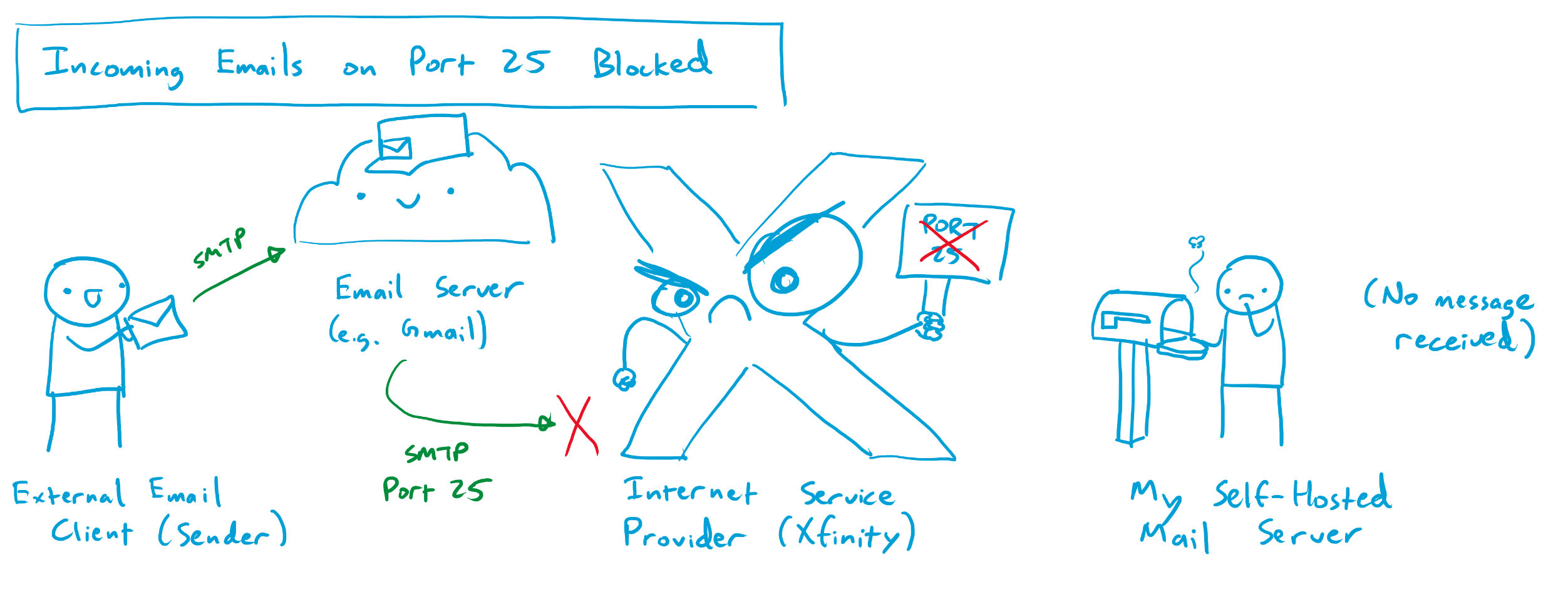
A wrinkle: Port 25 is blocked 🙁
I was originally convinced that setting up SMF would take a few hours, maybe an evening or two at most. The vast majority of the reviews and testimonials were from happy customers who were able to get it up and running in very short order. For some reason, I was simply unable to get any messages in, or out, of my SMF container despite a number of hours of effort. Pretty soon, I realized that most of the other users of the SMF image were happily doing so from the cloud, using Virtual Private Servers (VPSs) or other cloud compute instances with unrestricted access to the internet. It seemed like my problems were likely due in part to my webserver being hosted at my house on a residential internet connection.
After some digging, I found out that one of the ports I had forwarded from my webserver through my home router had been blocked by my ISP (Comcast). Running my mail forwarder required the use of two ports: port 587 (for SMTP traffic secured with encryption) and port 25 (the classic port used by mail servers to send and accept mail). Apparently, a while back, a few enterprising individuals found out that it was relatively easy to infect home internet users’ devices and have them send out copious amounts of spam email / malware / etc on port 25. Comcast and many other ISPs eventually had enough of this and figured that the best way to protect us from ourselves was to universally ban use of port 25 on any residential internet connection. Beyond the small handful of exceptionally irate superusers who hosted their own mail servers at home, nobody seemed to notice or care. Some of said irate superusers have managed, after great difficulty, to navigate the infinite fractal phone / email tree that is Comcast customer service in order to get port 25 unblocked for their service connection. Many more have failed, and the path to a successful port unblock seems to have gotten increasingly narrow and uncertain over the years. It seems that most Comcast employees have no idea what port 25 even is, and those who do are for the most part insistent that it is impossible to unblock for a given residential service connection. For a while, it seemed like this might be the end of the road.
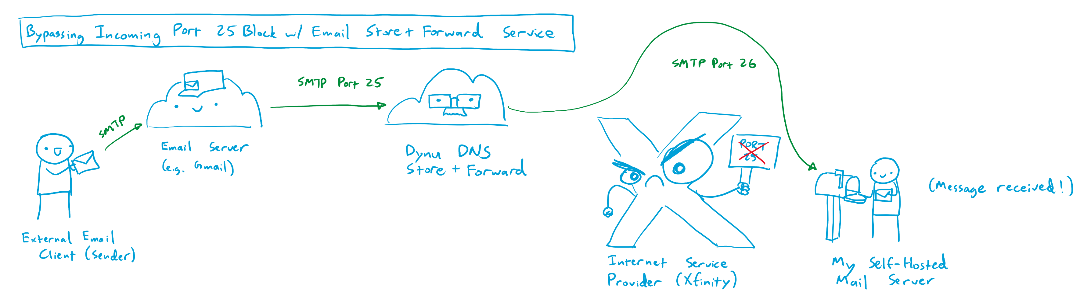
Unblocking Incoming Port 25 with an Email Store-and-Forward Service
By chance, I stumbled onto one of the aforementioned pissed off superuser threads where someone offered a helpful suggestion for allowing incoming mail to bypass port 25 on a residential internet connection. A company called Dynu DNS, based in Arizona, offers an email store-and-forward service that can operate on a different port from port 25. For a small fee of $10 per year, users can point the MX records from their domain towards Dynu’s mail servers, which accept mail from the internet on port 25, temporarily store the incoming messages, and then forward them to the users’ mail server on an arbitrary port that is not blocked by the users’ ISP, like port 26. This email store and forward service is relatively cheap, at $10 per year, but is locked to only a single domain. For instance, one store and forward service will only forward emails addressed to pantsforbirds.com, and I need to purchase a second service subscription to forward emails addressed to johnmcnelly.com. Still, for an additional cost of <$1 per domain, per month, this isn’t a bad deal, as it enables email reception for an unlimited number of email addresses at that domain!
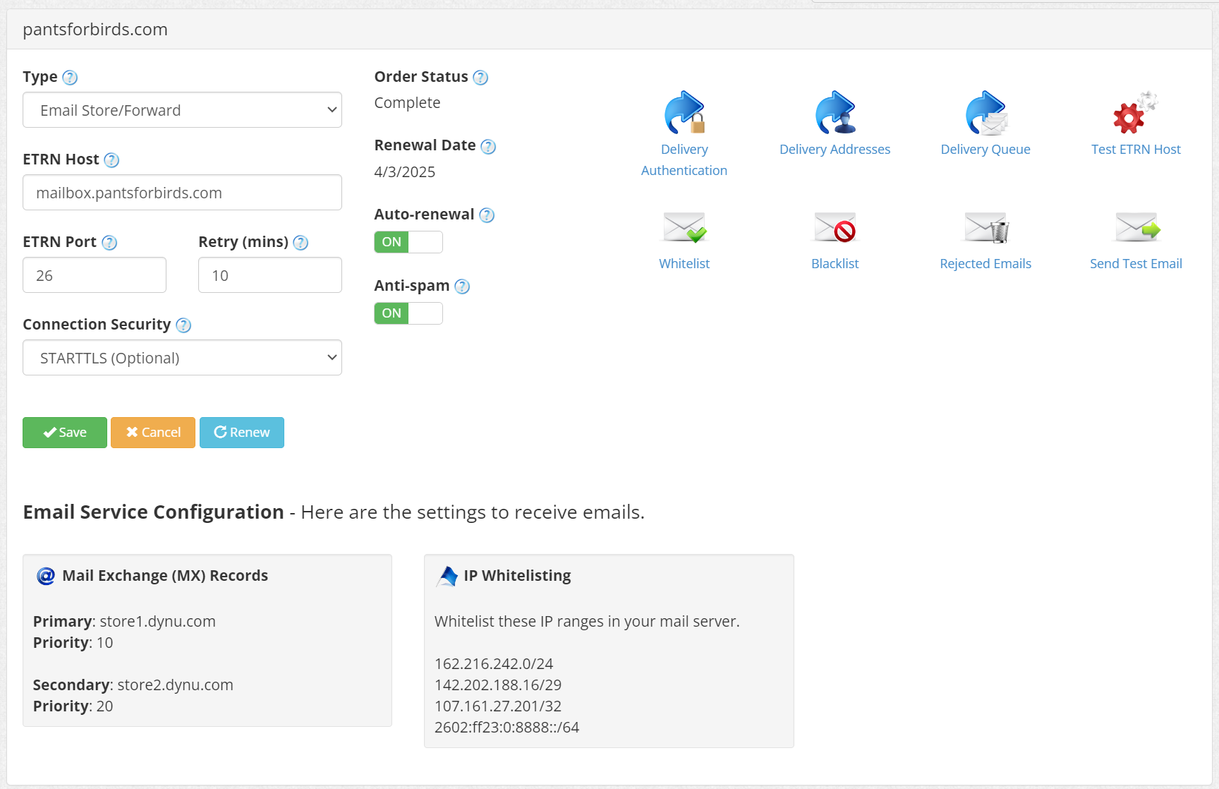
These are my settings for the pantsforbirds.com email store and forward service on Dynu.com. I’ve configured my MX records at pantsforbirds.com to point to store1.dynu.com, which receives incoming emails on port 25 and then forwards them to mailbox.pantsforbirds.com on port 26.
After configuring Dynu DNS’s store and forward service, I was able to send emails to john@pantsforbirds.com and have them forward properly into my gmail account. Unfortunately, I was still unable to send outgoing mail from my gmail account via my SMF docker container. Logs showed that messages were arriving into the SMF container, but then failing to send due to postfix being unable to connect to the destination mailserver.
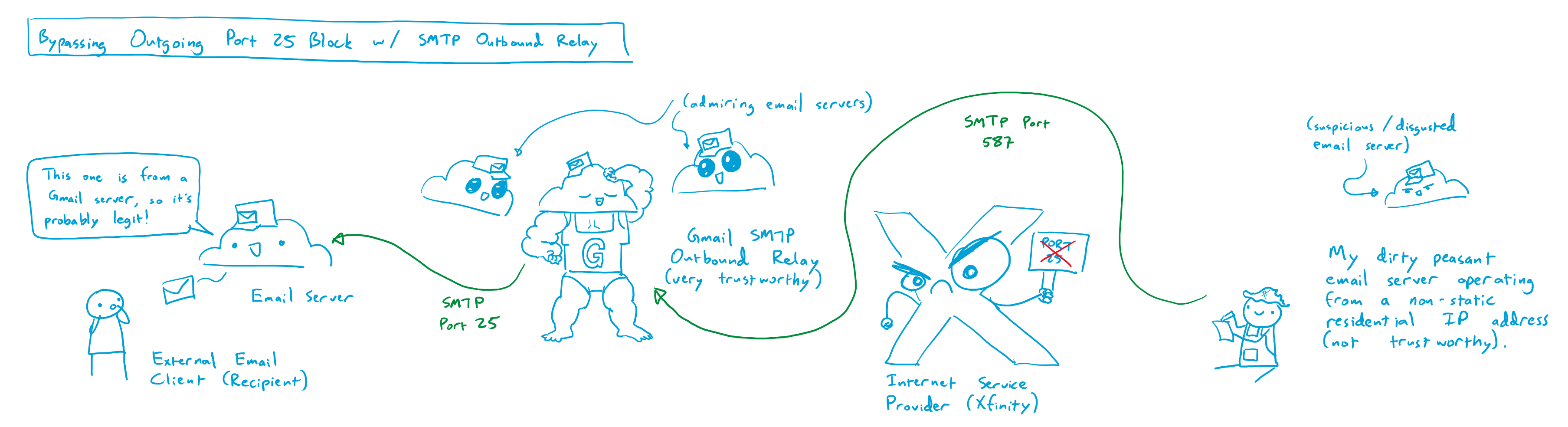
Sending Outgoing Mail with an SMTP Relay Service
After some digging, it became apparent that postfix was attempting to send outgoing mail to the destination mailserver on port 25, which was obviously blocked on my residential internet connection. There may have been some other clever ways around this, but the most straightforward seemed to be via the use of an SMTP relay service.
Much like the email store and forward service provided by Dynu DNS, and SMTP relay service receives and sends emails, but acts as an outgoing mailserver connector instead of an incoming mailserver connector. My SMF instance would connect to the SMTP relay service on an unblocked port, like port 26 or 587, and send an outgoing message over SMTP with TLS encryption. The SMTP relay service would receive this message, and then emit it to the destination mail server over the internet on the proper port (i.e. port 25). Using an SMTP relay service provides a number of side benefits beyond bypassing the port 25 block on a residential ISP:
SMTP Relay Services have static IP addresses that are not in residential IP ranges, reducing the likelihood that an outgoing email message gets marked as spam.
SMTP Relay Services can offer DKIM signing (discussed earlier), but I don’t use this feature since postfix already provides that option. This can be used to verify that an email message is authentic and was sent by an authorized user of a given web domain.
Dynu DNS offers its own SMTP Outbound Relay service, which is also quite affordable at $10/yr, but each service will only forward outbound emails for a single web domain. Dynu DNS is also not considered the most reputable source for email messages, so emails that are relayed through Dynu DNS often get dumped into the spam folder. Not great, especially for customer facing emails that could be important!
Fortunately, Google offers an SMTP relay service for Google Workspace users, which provides a reputable point of origin for outgoing emails. Google’s SMTP relay service is highly customizable, allowing outgoing email from a number of different addresses, supports encryption with TLS, and supports SMTP authentication with a generated app password (so you don’t have to put your primary Google account password into your mail server’s configuration files, and can revoke access to just the mail server if necessary). A Google Workspace account is quite a bit more expensive than the Dynu DNS Outbound Relay service, with a minimum price of $7/mo, but the ability to relay emails from multiple domains, and the reduced likelihood of having messages sent to spam, made the tradeoff worthwhile for me.
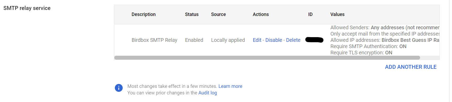
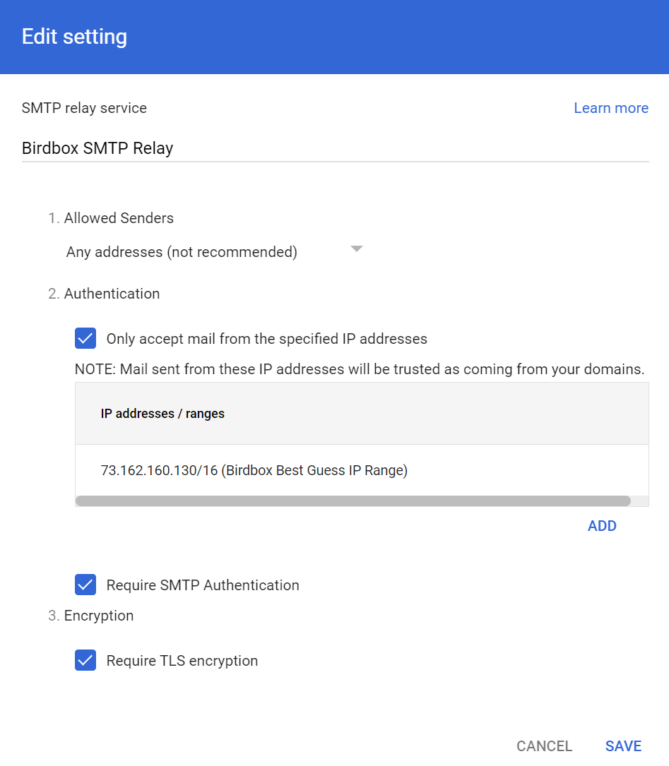
Setting up the Google SMTP outbound relay was relatively straightforward when following the instructions provided by Google. Here’s the settings I use for the SMTP outbound relay in my google workspace:
The IP range is set to my best guess at the entire block of available IP addresses that I might get assigned by my Residential ISP (Comcast / Xfinity). Any email address can send a message using the SMTP outbound relay, so long as they provide the correct credentials. In my case, this means that emails from @johnmcnelly.com or @pantsforbirds.com can both be processed through this single SMTP relay.
Funnily enough, the trickiest part of getting the SMTP relay working for me was getting the syntax correct for the SMF_RELAYHOST variable in my configuration file; postfix required some pesky square brackets before a port number that wasn’t mentioned in any of the documentation that I could find. I’ve included an anonymized .env file in the next section to hopefully save other adventurers some trouble!
SMF .env file
# Add email mappings here in the form "website_email_address:forwarded_to_address:password".
# NOTE: All accounts must have passwords or else they will be auto-generated, or set to match password of first account.
SMF_CONFIG="@website:forwardtoemail@email.com:smtppassword1;
username@website:forwardtoemail@email.com:smtppassword2"

# Note: SMF_DOMAIN needs valid siged TLS certificates for TLS to work!
SMF_DOMAIN="mail.website.com"
SMF_CERT_DIR=/etc/postfix/cert # Used in the Certbot container to figure out where to copy web certs to allow them to be used for SMTP.

SMF_RELAYHOST="[smtp-relay.gmail.com]:587"
SMF_RELAYAUTH="relayuser@website.com:<app password>" # Use an App Password for Google SMTP Relay.

# Timezone
TZ="America/Los Angeles"

# Stop emails from getting hard rejected until I'm sure the config is right.
SMF_POSTFIXMAIN_soft_bounce=yes
Tada!
Well, that’s pretty much it! With an email store and forward service to bypass port 25 on the way in, and an SMTP relay service to bypass port 25 on the way out, self-hosting a Mail Transfer Agent on a residential internet connection is quite workable!
I’ve been using my SMF instance for a few months now, and it seems to work without much of an issue (although the Gmail inbox I forward incoming mail to sometimes doesn’t like that it comes in via the Dynu DNS servers, and marks some messages as spam).
Mucking through this email adventure probably took me something like 40 hours total, so it was a little while before I finally got around to requesting those free chip samples using my fancy corporate email address (john@pantsforbirds.com). The company promptly replied that they were unable to ship me free samples, as they don’t ship to PO boxes nor residential addresses. Sometimes the real “free samples” is the amorphous blob of IT knowledge we collect along the way. 🫠
I love working with the Pi Pico / RP2040 microcontroller, but setting up the pico SDK can be a bit of a pain in the butt, especially while hopping across a few separate devices and operating systems (as I was for a while).
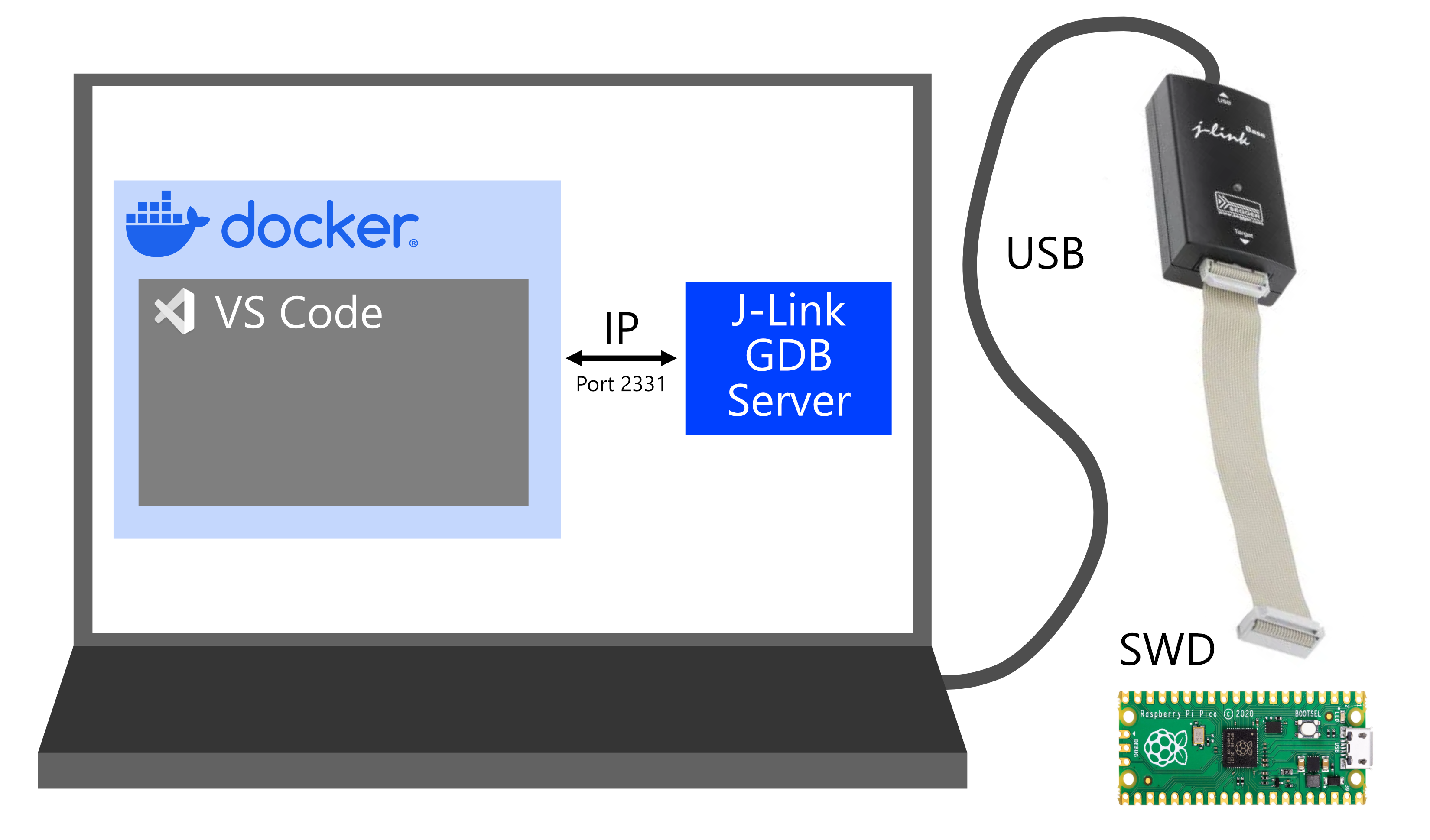
After a few years of messing around with it, I’ve settled on a reasonably painless solution for developing with the Pico that uses a custom-built docker container loaded with the pico SDK, arm-none-eabi compiler and debug tools, and the JLink debugger utility. With this setup, you can easily compile and debug programs for the Pi Pico / RP2040 by adding a single docker compose file to your project repo, mapping in the directories that you want to be bind mounted into your docker container, and setting up a VS Code .launch file to work with JLink.
Software and Hardware Requirements
You’ll need the following software installed on your computer:
This workflow is intended for use with a J-Link debugger, like the J-Link EDU, J-Link Base, and J-Link Plus. I personally use a J-Link Base, please let me know if there are any issues with other debuggers!
Installation
Docker Compose File (compose.yml)
Add the following code into a file called compose.yml in your project directory.
version: "3.2"
services:
  pico-docker:
    image: coolnamesalltaken/pico-docker:latest
    volumes:
      - type: bind
        source: . # Which directory from the host computer gets mounted to the container.
        target: /project_directory # Where the directory gets mounted in the Docker container.
      # You can bind additional project directories to the container with more - type: bind commands,
      # or create volumes that give the container its own storage.
    command: tail -f /dev/null # keep the container running forever
VS Code Configuration (launch.json)
This file is still somewhat a work in progress, but works well enough for me as it is. I do notice that I have to reset the device using the VS code debug buttons to get a firmware upload to complete properly, so there might still be some settings that I’m missing. Anyways, adding this file into your .vscode folder as launch.json will allow you to connect to your RP2040 from within the docker container, via an IP connection to the JLink GDB server running on your host machine (which in turn is connected to your JLink debugger via USB).
{
    // Use IntelliSense to learn about possible attributes.
    // Hover to view descriptions of existing attributes.
    // For more information, visit: https://go.microsoft.com/fwlink/?linkid=830387
    "version": "0.2.0",
    "configurations": [
        {
            "name": "Remote Debug",
            "type": "cortex-debug",
            "cwd": "${workspaceRoot}",
            "executable": "${command:cmake.launchTargetPath}",
            "request": "attach",
            "servertype": "external",
            "gdbPath": "arm-none-eabi-gdb",
            "gdbTarget": "host.docker.internal:2331",
            "showDevDebugOutput": "raw",
            "svdFile": "/usr/local/pico-sdk/src/rp2040/hardware_regs/rp2040.svd",
            "preRestartCommands": [
                "file ${command:cmake.launchTargetPath}",
                "load",
                "monitor reset"
            ],
            "device": "RP2040",
        }
    ]
}
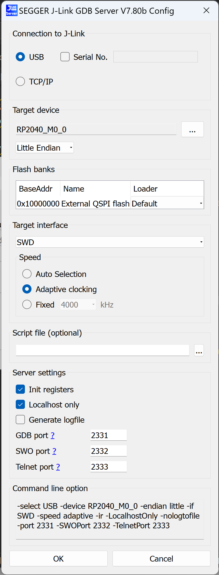
J-Link GDB Server Settings
These are the settings I use for the J-Link GDB server that I run on my host computer.
Usage
When everything is set up and running, the development workflow looks like:
Launch Docker Desktop on the host computer.
Run docker compose up in your project directory where the docker compose file resides on your host computer.
Launch VS Code on the host computer and attach a remote VS Code editor to the pico-docker container.
Launch J-Link GDB Server on the host computer and connect to the RP2040 over USB.
In the remote VS code editor, you can edit your code, compile and debug your code on the container with GNU gcc/g++/gdb, compile your code for the target with arm-none-eabi gcc/g++, and upload your code to the target via J-link using the launch.json file provided. Additional directories with libraries like googletest can be bind mounted to the docker container by editing compose.yml if you want to use unit tests!
After our DMV themed Halloween costume last year, our Halloween crew was searching for a new costume idea that would be equally frightening for both children and adults. In March 2023, we had our answer.
What’s Silicandy Valley Bank?
In the months before Halloween, we began planning our costume with a rather ambitious objective: construct a fully functioning bank that utilized Halloween treats as currency, and have it fail in a spectacular fashion. Since it’s rather difficult to invest liquid treat capital into long-term Treasury bills, we needed a different way for our bank to collapse. We settled on using a combination of aggressive deposit incentives (to get large numbers of kids to open an account), ludicrous interest rates, and poor fiscal controls to try getting the bank to collapse in an obvious manner, with the hope of inciting a bank run as the obviously floundering bank obviously ran out of money (treats). As it turns out, building a fully functional bank that opens hundreds of accounts, tracks interest on said accounts, and then collapses spectacularly in a few hours is pretty complicated. The fully realized “Silicandy Valley Bank” had a lot of moving parts, and succeeded in its task of pleasing a large number of children while failing spectacularly, just not in the manner that was originally intended.
How was SVB supposed to work?
Getting kids to open a “bank account” with treats is actually a bit more difficult than doing it with cash. Candy is very much unlike fiat currency; in addition to being unable to pay your taxes with it, each piece of candy is rather unique. Besides the obvious flavor and size differences, kids care a lot about other details, like “has this chocolate bar been melted in somebody’s pocket” or “did someone lick all the sour flavor coating off of these Skittles”. We also wanted to avoid the potential liability associated with handing out treats originally gathered by one kid to a different kid (e.g. the aforementioned “pre-licked candy” issue). These issues could be avoided by sequestering treats by account number, so each kid would never receive treats that were originally deposited by a different kid, but this would be a huge inventory headache
In the end, we decided the easiest solution was to only give out treats that were roughly equivalent in value, and not accept actual deposits from trick or treaters. This was accomplished via an “incentive deposit” system.
The workflow was supposed to go something like this:
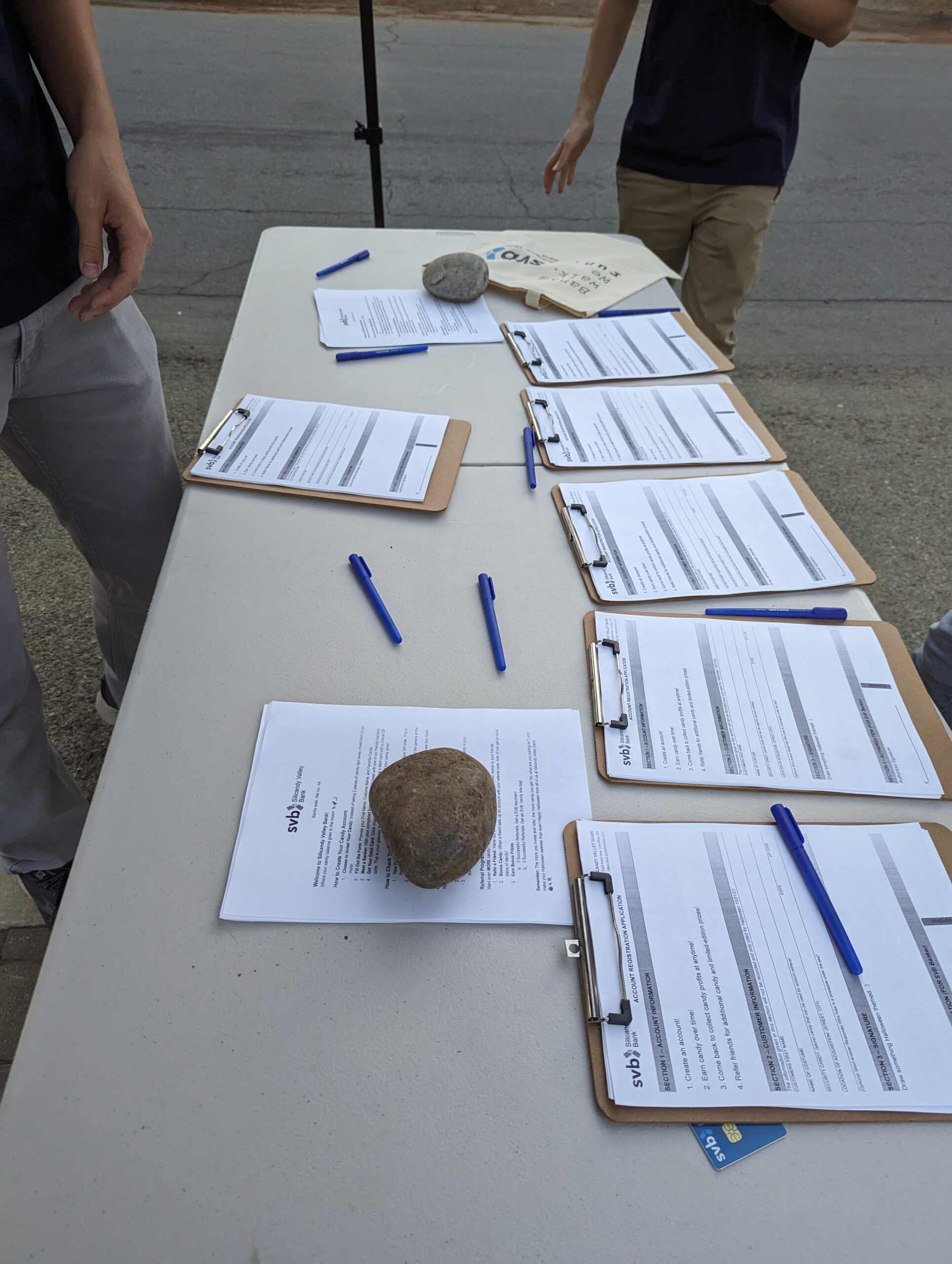
A Trick or Treater (TOT) shows up to the bank, and is provided a form to fill out in order to open their account.
The TOT waits in line then goes up to the next available banker to open their account.
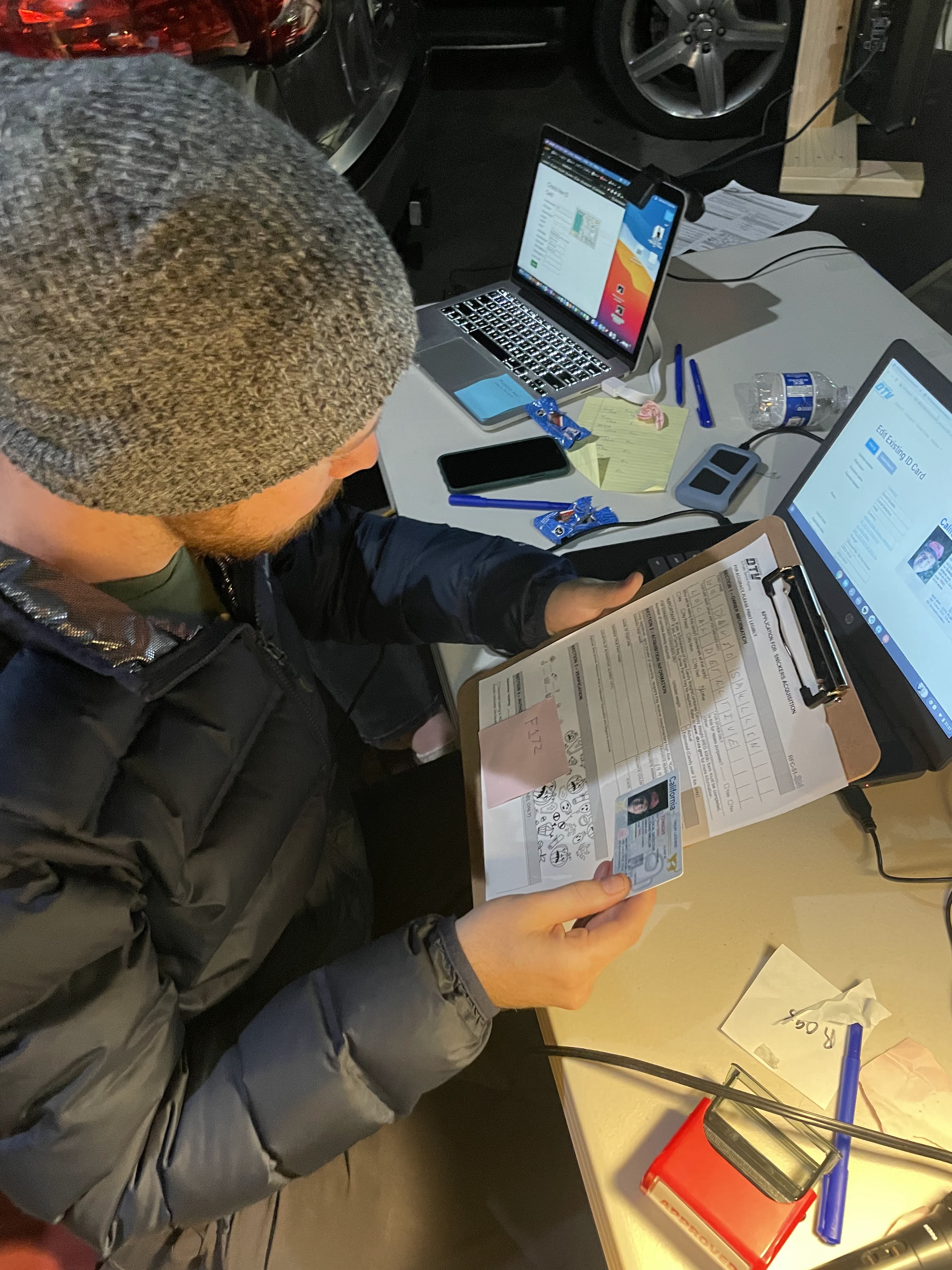
The banker reviews the TOT’s form and uses their computer to open a new account. The TOT is provided with an initial incentive deposit of two pieces of candy. The TOT can withdraw one or both pieces of candy immediately, or leave the candy in their account with a ludicrously high interest rate, to come back and claim a higher balance later in the night.
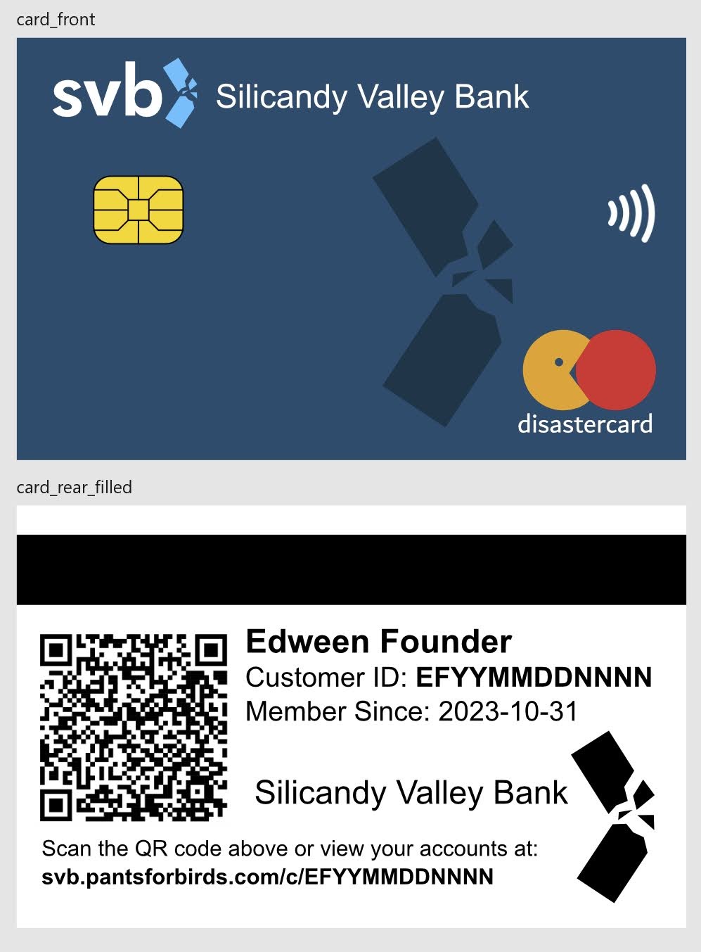
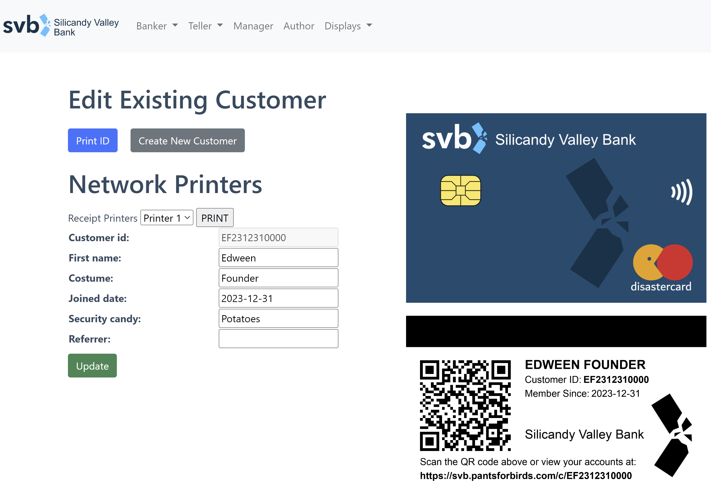
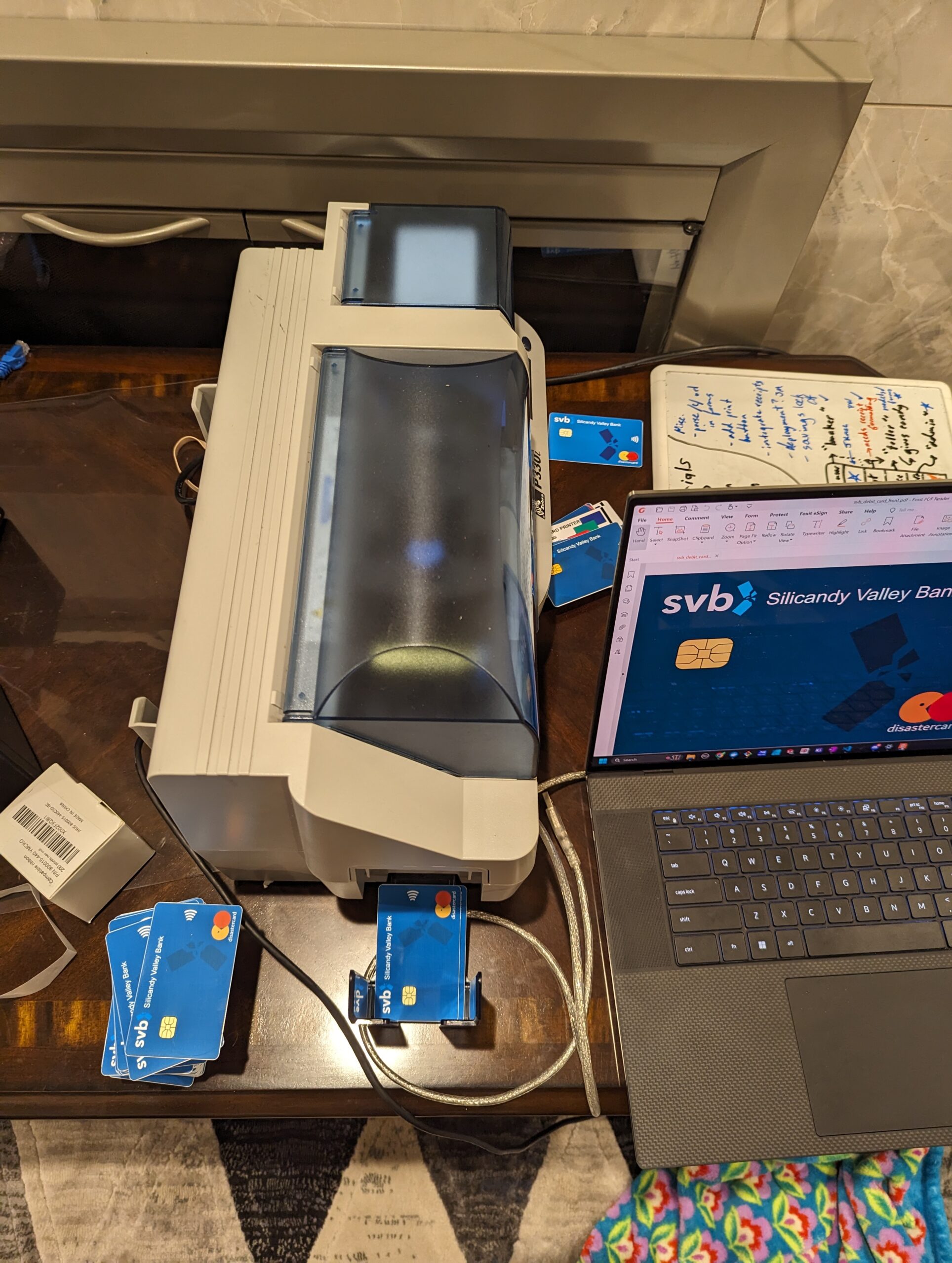
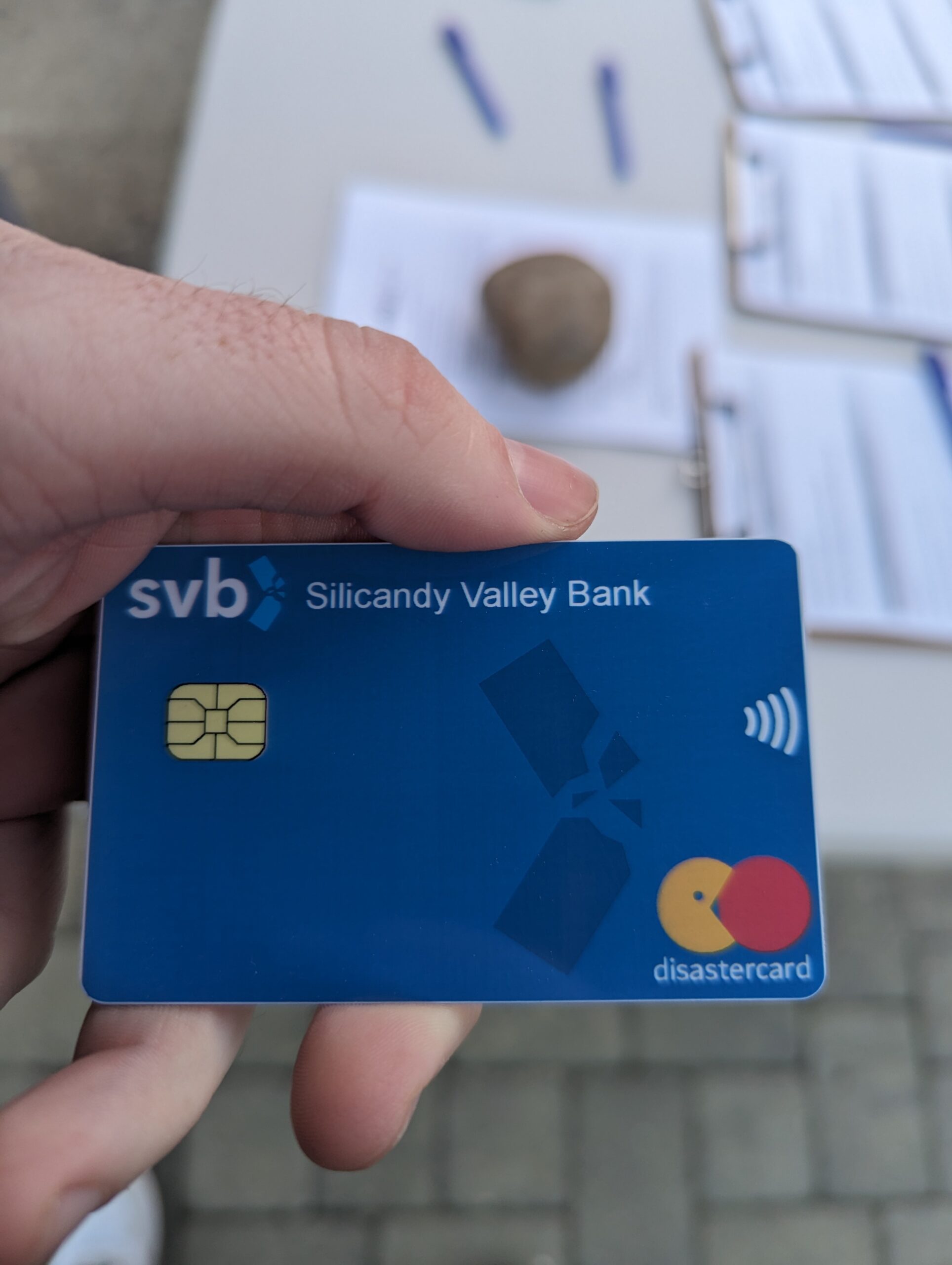
The banker prints out a debit card for the TOT linked to their new account. Printed on the debit card is a web URL that can be used to view the account balance, as well as a QR code that can be scanned by a smartphone to open the same account page. When scanned by the banker, the same QR code is used to pull up the TOT’s account in order to make deposits or withdrawals.
TOT goes and does TOT things, while occasionally checking their account balance.
Just as the TOT’s balance begins to get really big looking, they see notifications on their account page (and hear from other kids) that the bank might be running out of candy soon, since so many other kids have opened high interest rate accounts, and the bank is only distributing candy (via new account incentive deposits + interest) and never actually increasing its reserves.
Chaos.
The Federal Treat Insurance Corporation steps in to save the day, disbursing candy up to the Insured Amount(TM) of each account.
For an added twist (since this somehow didn’t seem complicated enough), we added a referral system that would allow TOTs to open an account with another TOT’S referral code, thereby providing both TOTs with an additional piece of candy added to their account balance. We even got partway through implementing peer to peer account balance transfers on the day of Halloween, before things exploded in a rather spectacular fashion in a manner that we had not anticipated.
But first, let’s talk about the pieces of the costume that made it possible!
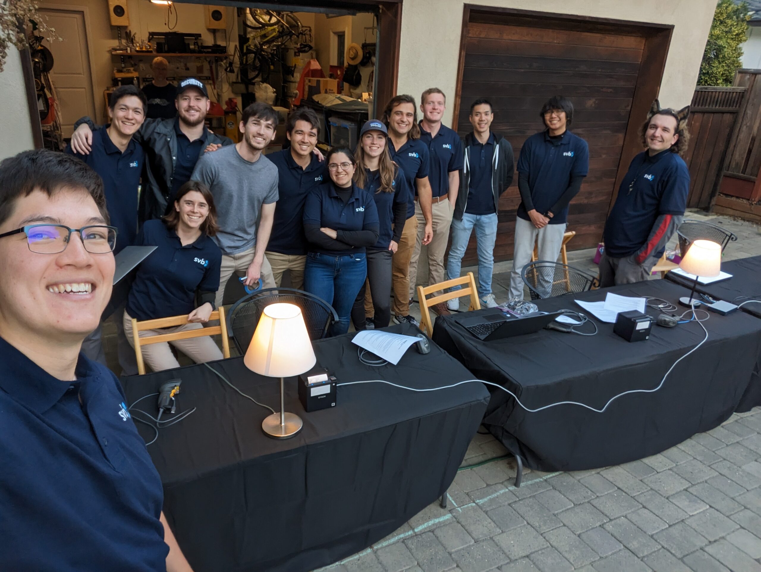
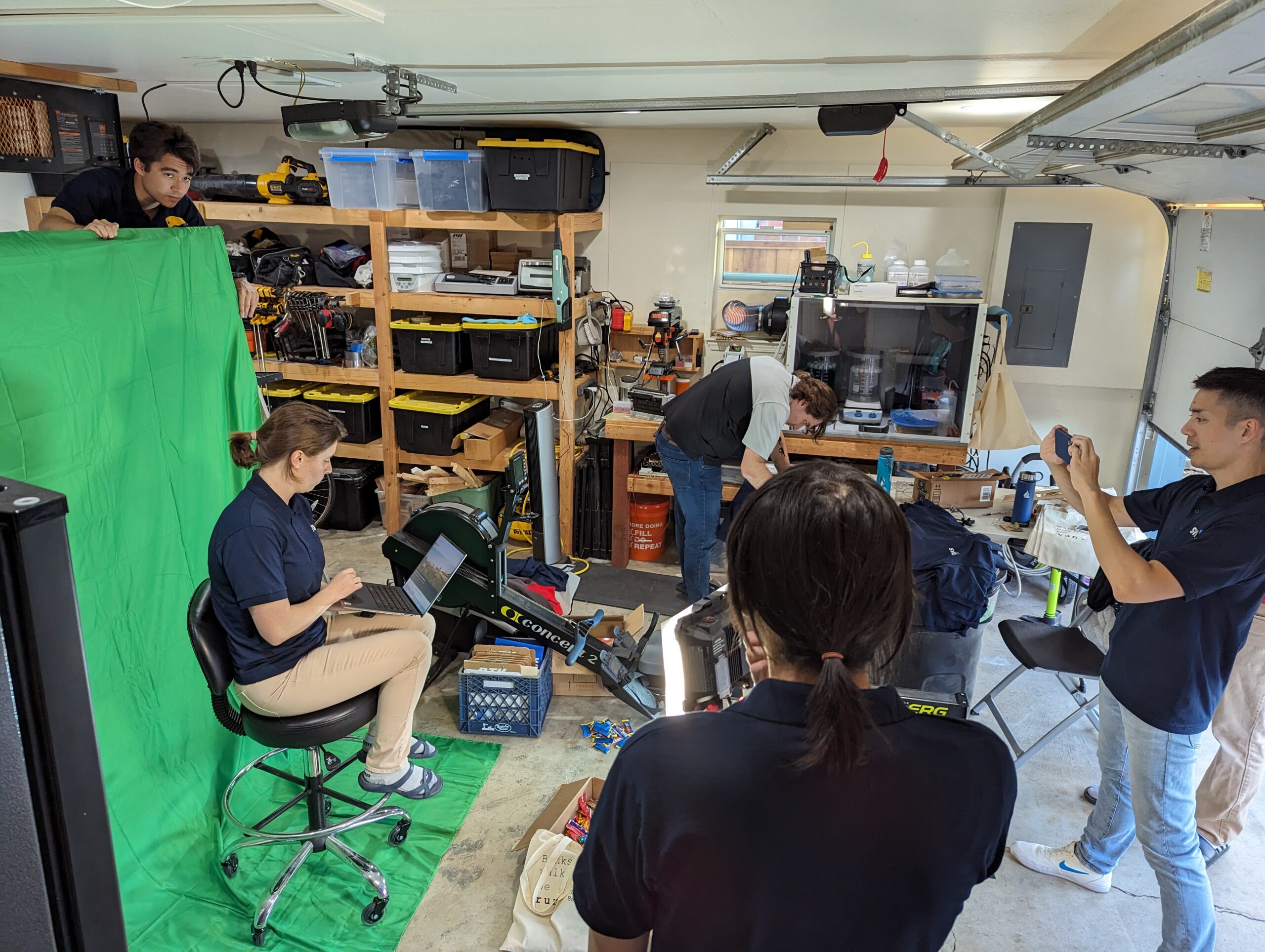
Piece 1: The Team
The most important part of this project was the excellent collection of friends who made it happen! As our most ambitious Halloween project yet, it wouldn’t have been possible without hundreds of person hours from 14+ contributors.
Riding off the success of 2022’s DMV costume, we had a dedicated crew of volunteers who were excited to do something crazy for Halloween once again. Our volunteers had a good spread of knowledge and engineering capabilities, ranging from data science to mechanical engineering and frontend web design. We did our best to tailor the costume to the skilled labor that we had available, while also creating something that could be accessible to TOTs. Many late nights were spent cutting vinyl, fiddling with ESC-POS receipt printers, rebuilding and ID card printer from the early 2000’s, resolving merge conflicts, and designing costumes and sets. When some of the more critical parts of our IT infrastructure tossed their cookies on the night of the big event, our crew pulled together to cover the gaps and keep the show running for hundreds of kids. I couldn’t have asked for a better team!
Costume Participants:
Kenneth McNelly, Noah Kjos, Caitlin Hogan, Paul Walter, Matthew Trost, Anika Hanson, Jillian MacGregor, Nicolas Weininger, Jeff Barratt, Scott Kwong, Alexander Zhang, Jason Kmec, David Gonzalez, Michal Adamkiewicz.
Special Acknowledgements:
Website and IT systems contributors: Caitlin Hogan, Morgan Tenney, Paul Walter, Jason Kmec, Cale Lester
Props: Jason Kmec, David Gonzalez, Alexander Zhang
Operations: Kenneth McNelly, Matthew Trost
Skit Actors: Matthew Trost, Paul Walter
Video Editing: Scott Kwong, David Gonzalez
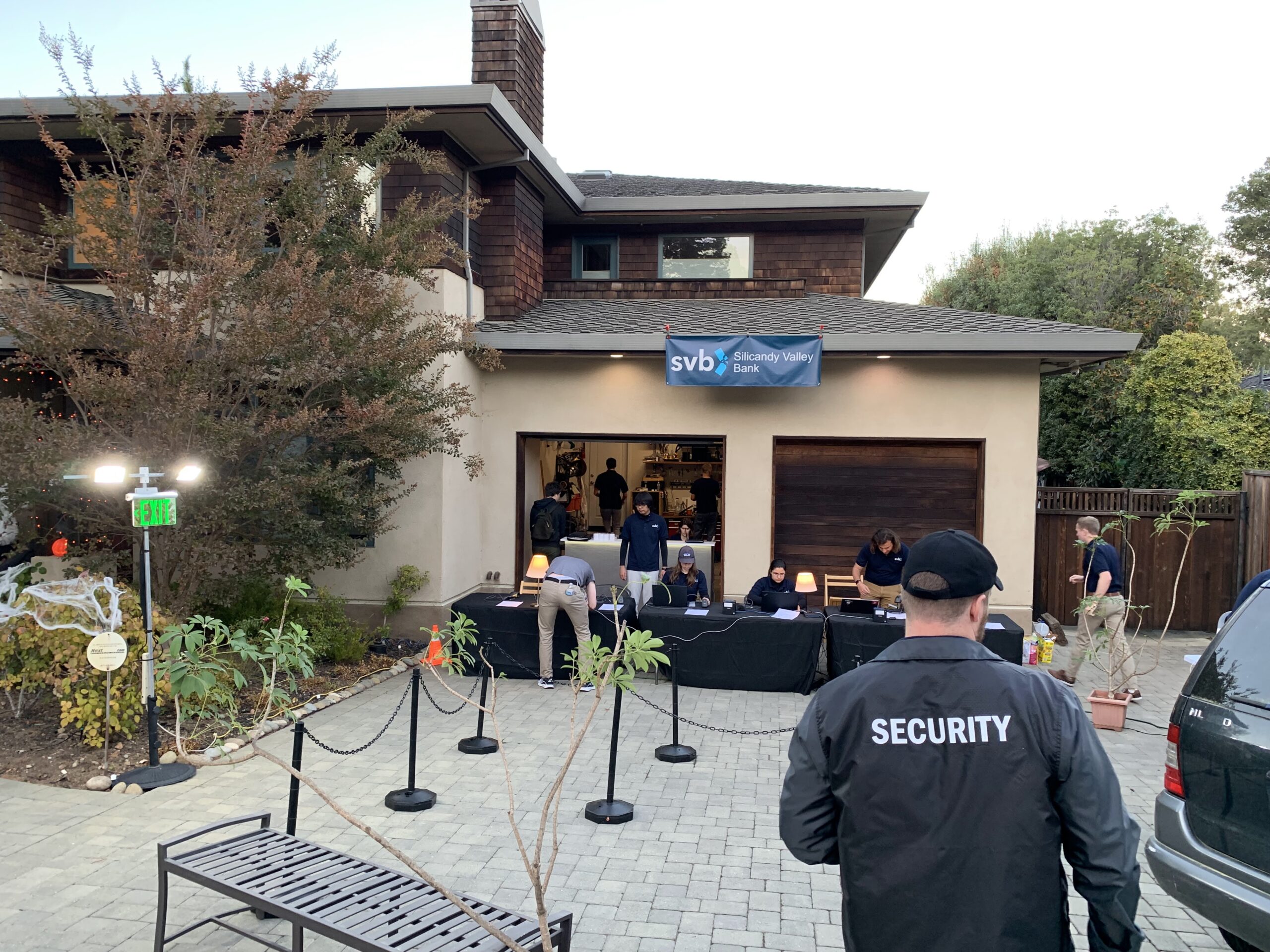
Piece 2: The Website
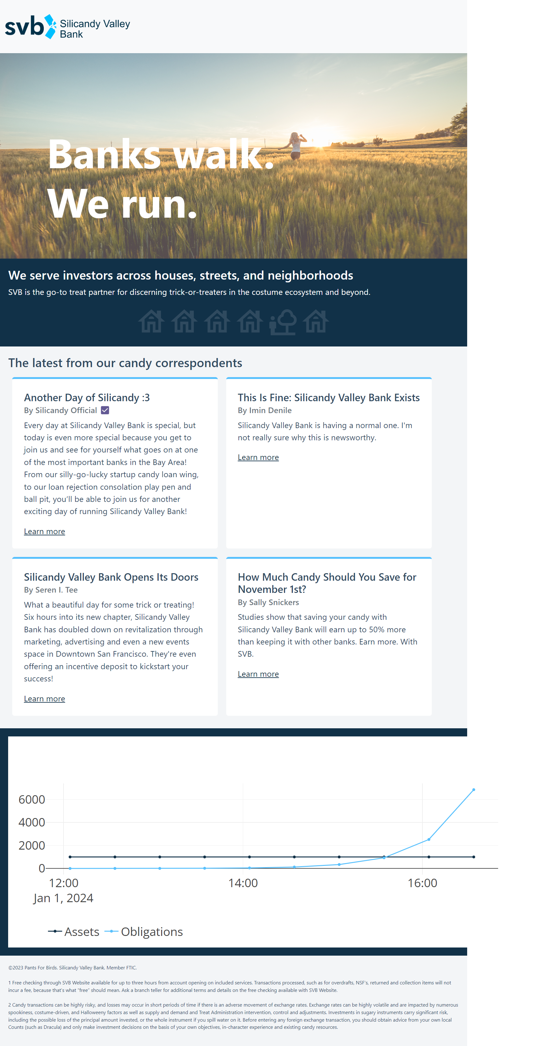
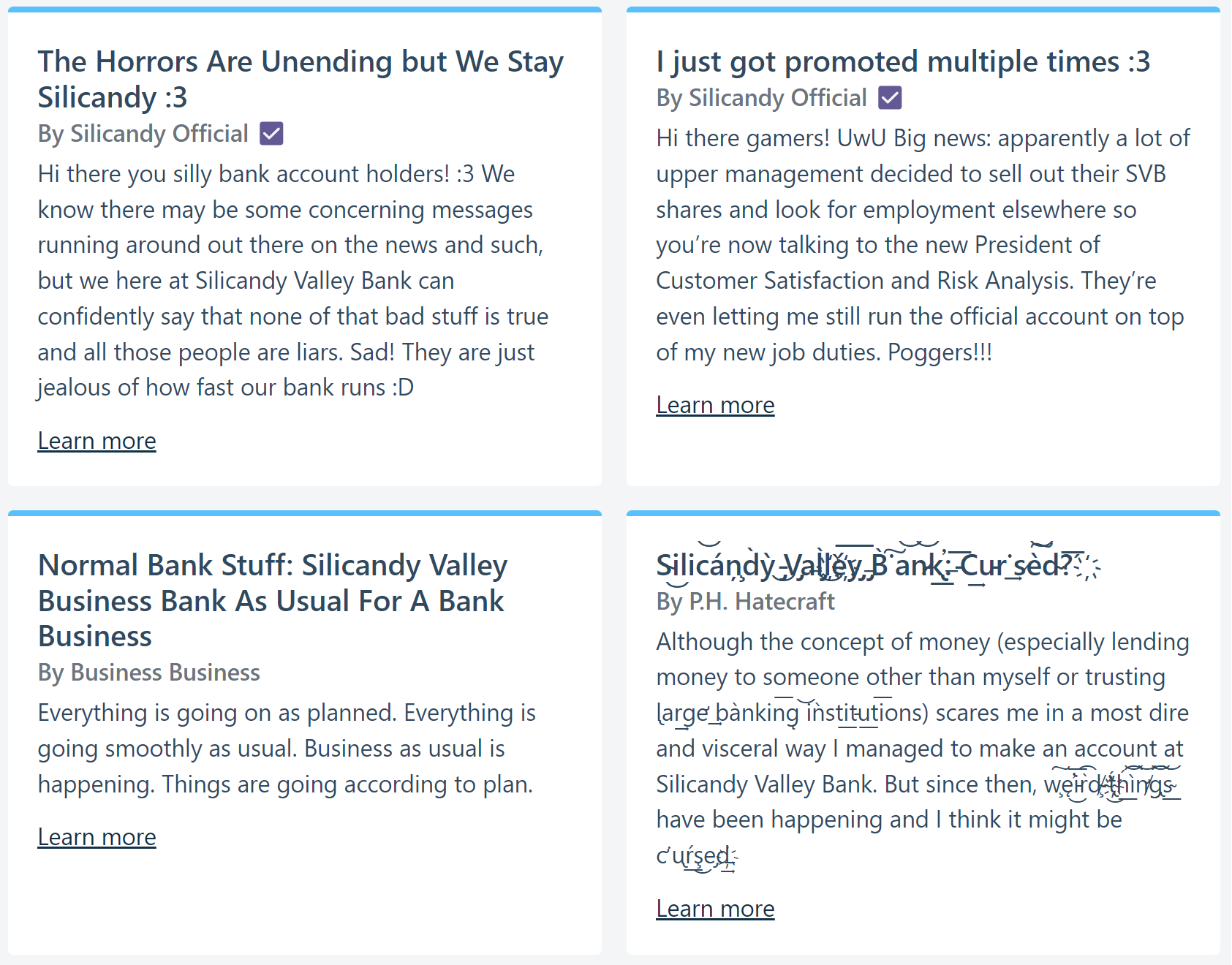
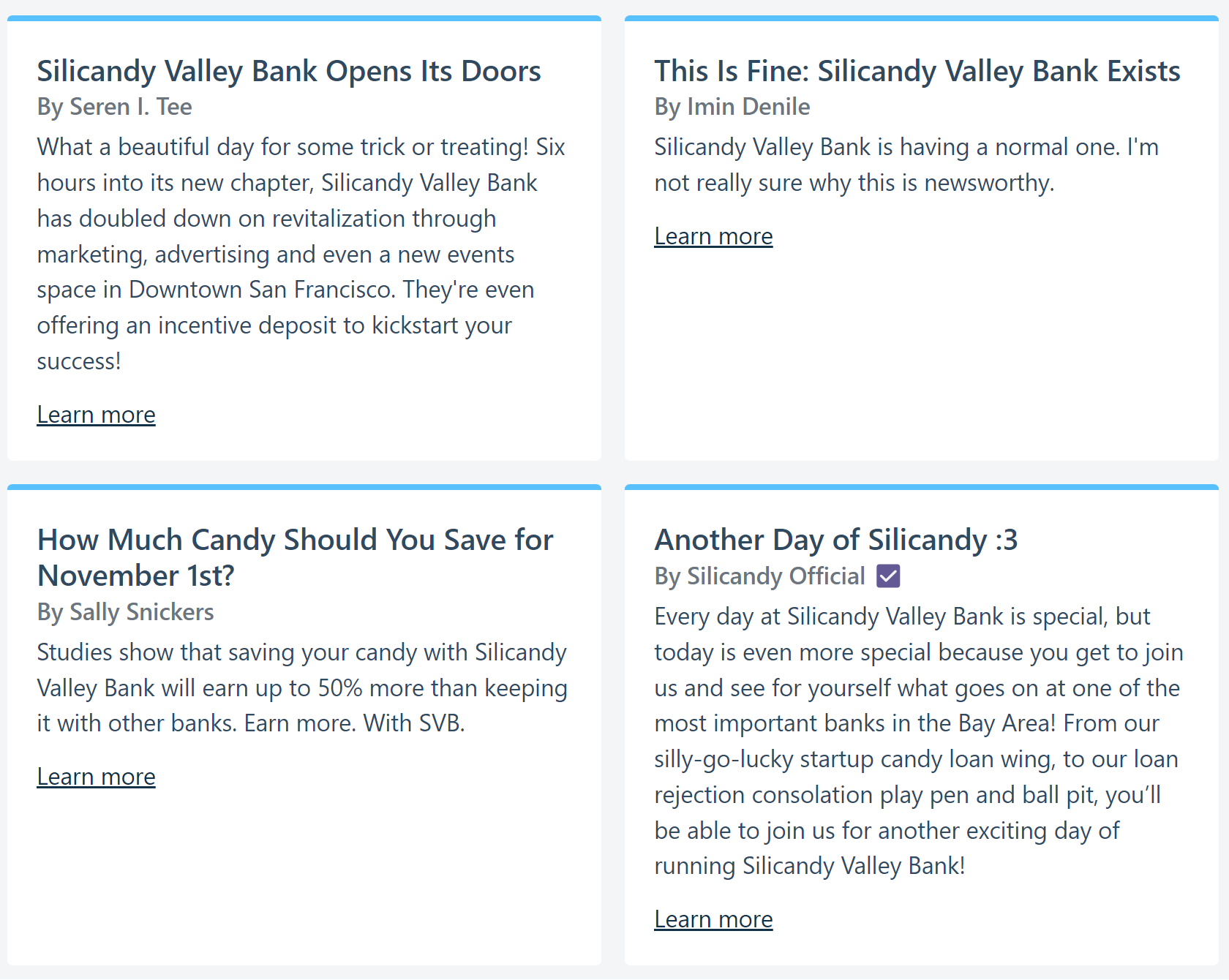
As originally designed, the core of Silicandy Valley Bank’s IT infrastructure is its website, which contains both a customer-facing account interface as well as an internal website for creating customer accounts, updating account balances, and printing debit cards. There’s also a special “god mode” view, which allows an admin to adjust bank reserves and release a series of increasingly panicked pre-prepared “don’t worry everything is fine” blog posts on the website. The website was intended to serve as the glue between all the other puzzle pieces: bank employees would use it to process TOTs through the costume, TOTs and parents would use it to track the progress of their accounts and see the bank “run” in real time, and its various drivers would run all the required IT infrastructure on site, including barcode readers, receipt printers, ID card printers, and infotainment displays.
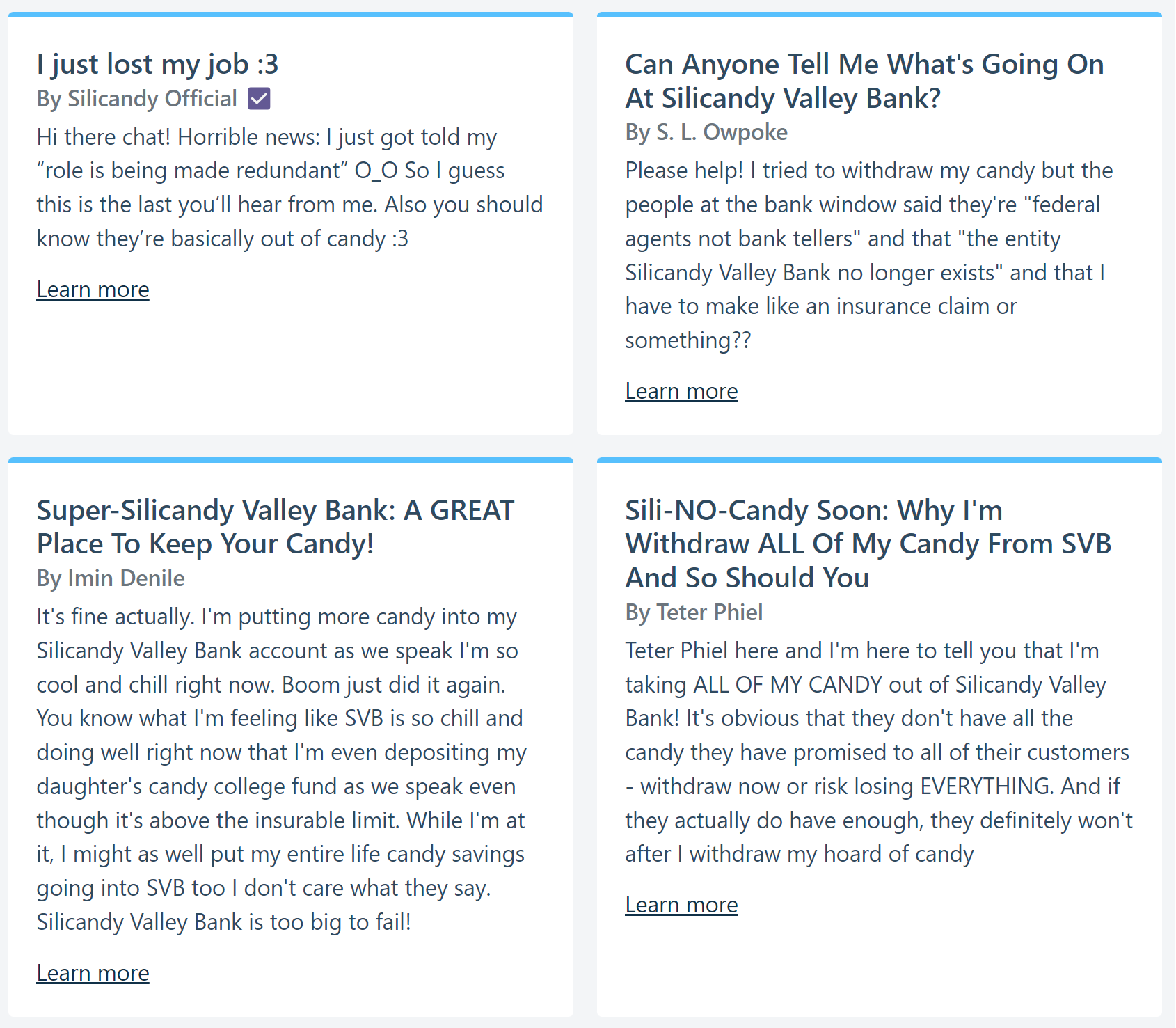
Eek level 3-5 blog posts.Eek level 1-3 blog posts.Eek Level 0 blog posts.
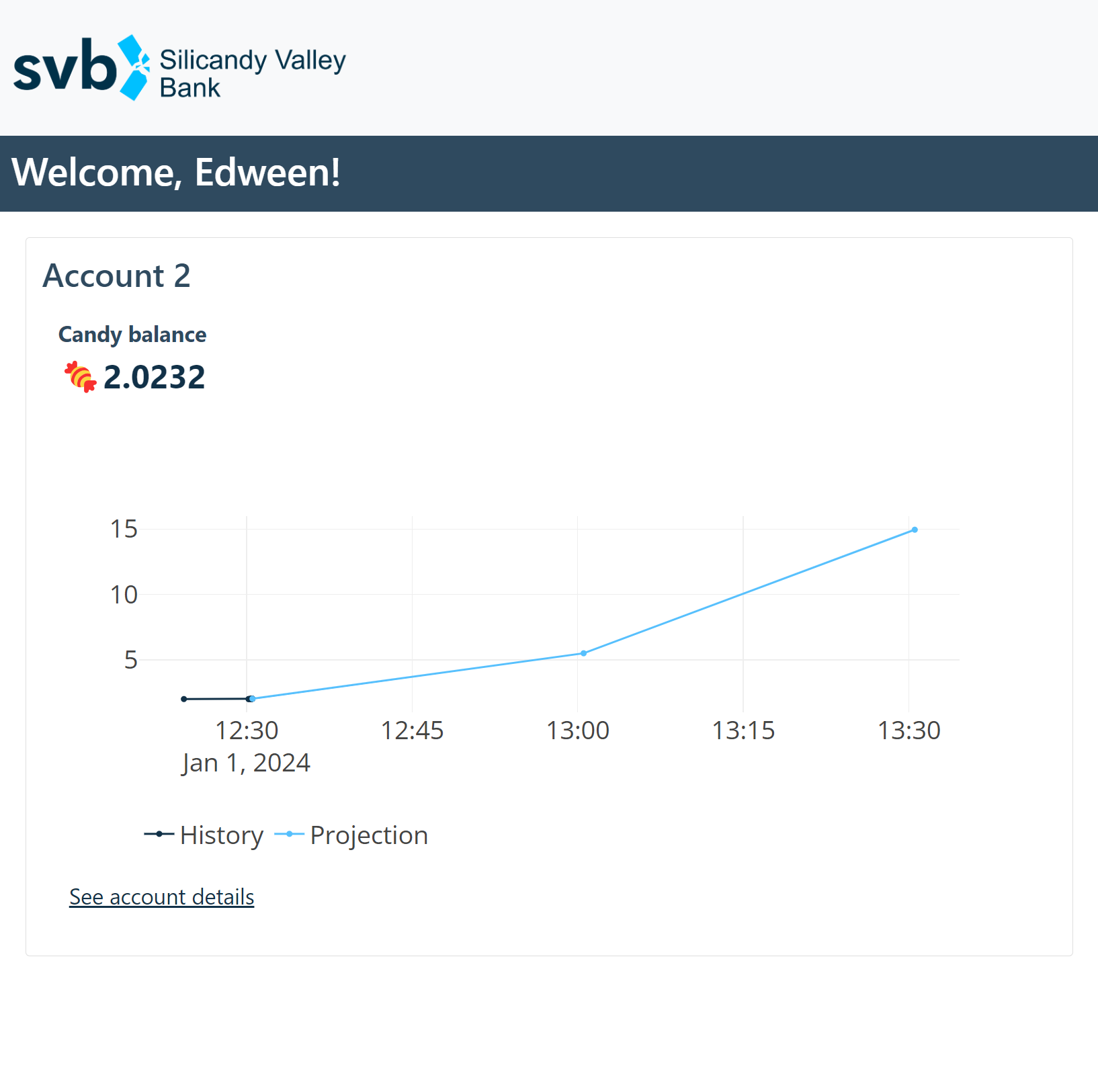
The public-facing homepage of the website was registered on a subdomain of my project website, pantsforbirds.com, with a proper HTTPS reverse proxy at https://svb.pantsforbirds.com (the server is no longer live, since the website is held together with spit and tape and only intended to run for a few hours–compound interest rates are high enough that if left running for a few weeks with nonzero interest rates, the website database has numerical overflow issues). This homepage displayed a live-updating chart of the bank’s current reserve balance, as well as the outstanding liabilities it had (in the form of treat deposits + interest). During the course of trick-or-treating, we were expecting to see the reserve balance plummet as TOTs withdrew the candy associated with their original incentive deposit and accrued interest. Simultaneously, we expected the liabilities balance to skyrocket as new accounts were created and interest accrued, since the bank was never receiving real deposits, and was strictly giving away candy with the free “incentive deposits” it added to every new account. When these two lines crossed, the bank would fold, as its liabilities would exceed its available reserves.
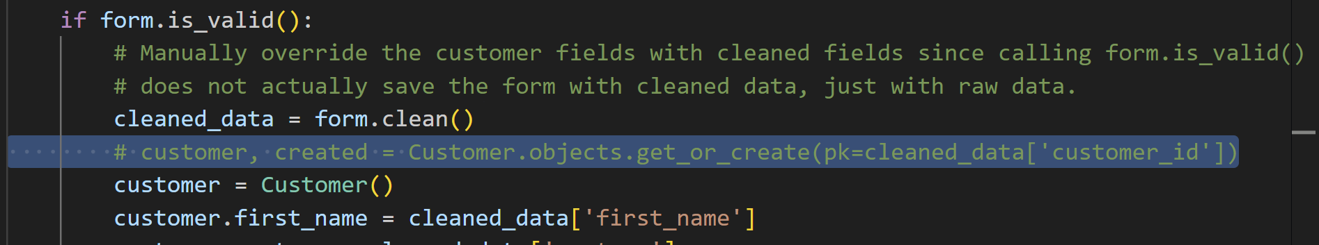
While bank reserves and liabilities are admittedly a bit of a complicated concept for trick or treaters to grasp, we hoped that parents might be able to clue their kids in that they might want to withdraw the candy sooner rather than later, leading to a desired “bank run” effect. Each TOT was intended to receive a debit card with a QR code that they could scan in order to visit their personalized account page, at https://svb.pantsforbirds.com/c/<customer_id>. This customer page would display their current account balance, current interest rate, as well as the bank’s overall reserves (so they could tell if a run was starting).
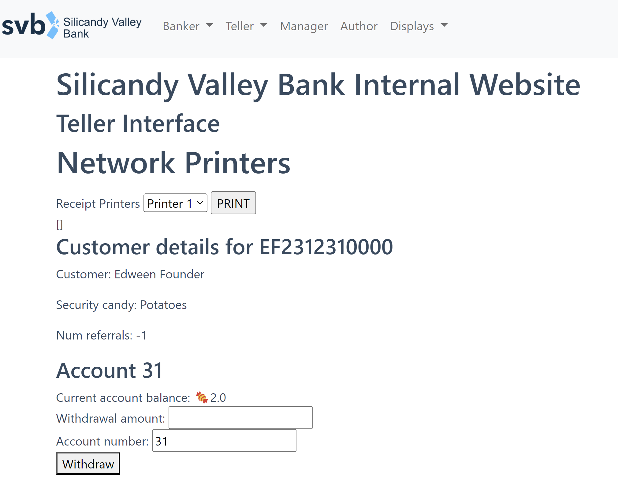
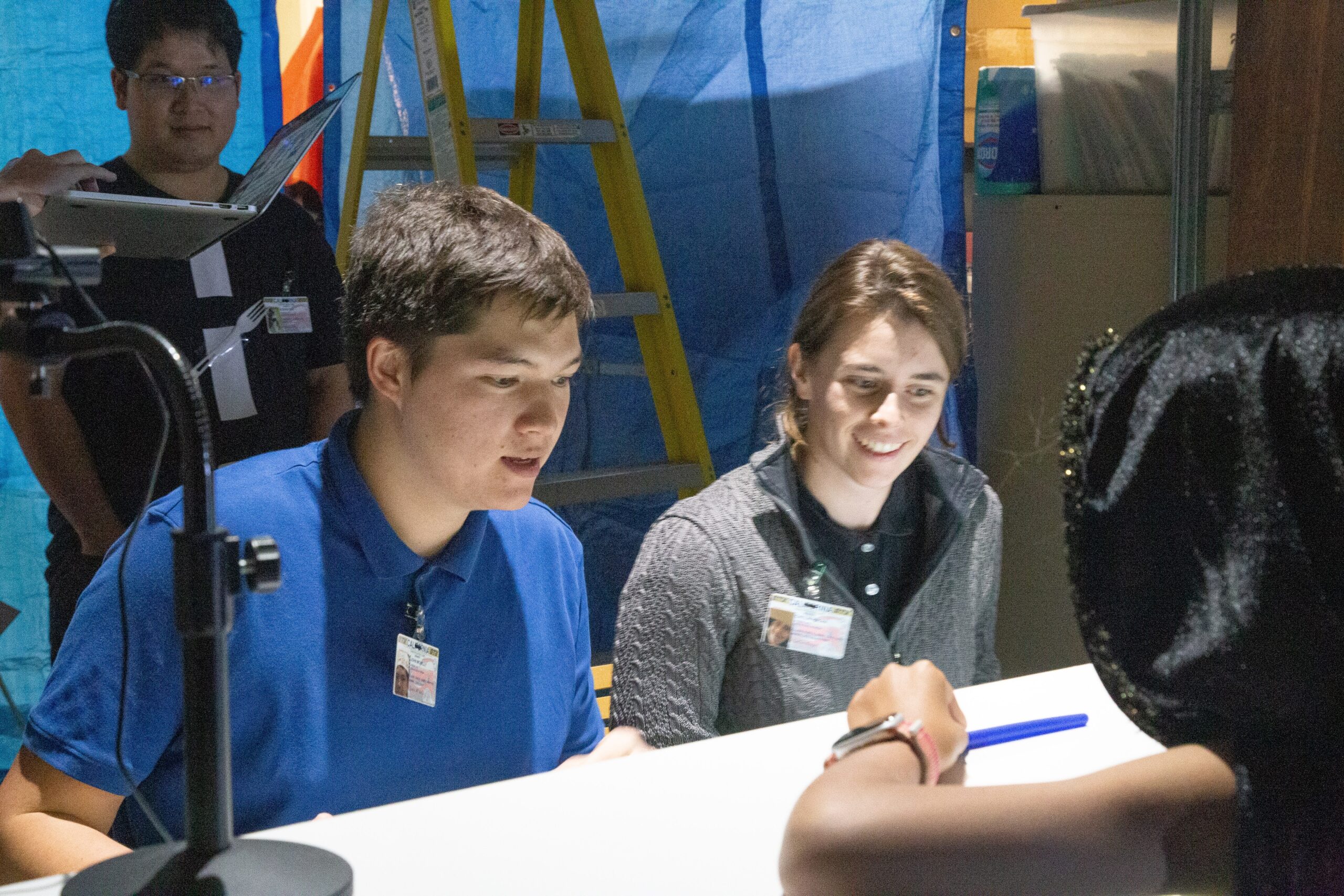
On the back end, an internal site was accessible via login for Silicandy Valley Bank employees. Interfaces were available for creating new customers, withdrawing account balances, and referrals. 2D barcode scanners connected via USB to each employee’s laptop allowed easy scanning of debit cards to quickly open a TOT’s bank account and withdraw treats as necessary.
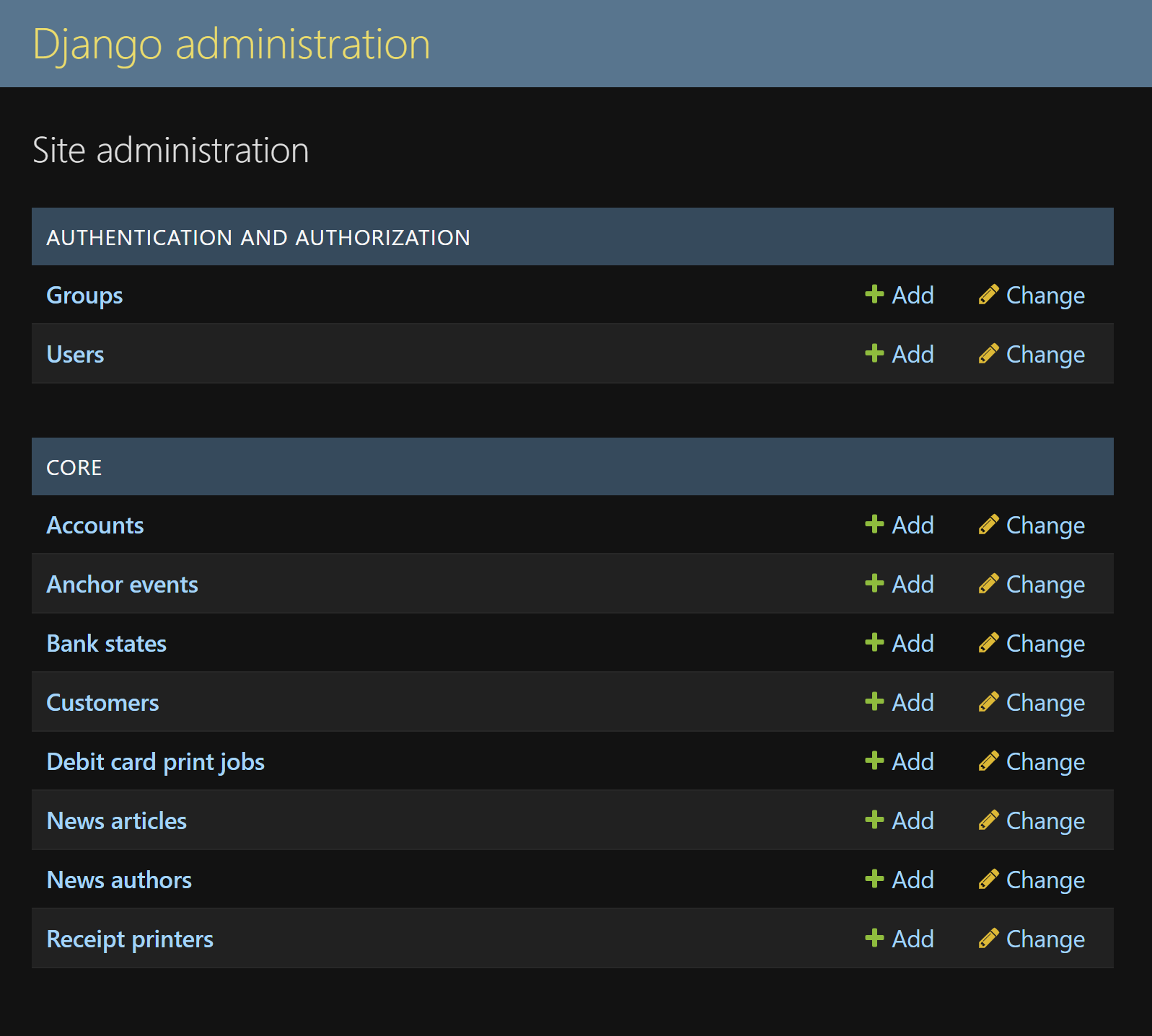
Banker interface for creating new customer accounts and printing debig cards.Teller interface for withdrawing candy from accounts.Django database administration view, showing the various models used to run the bank.
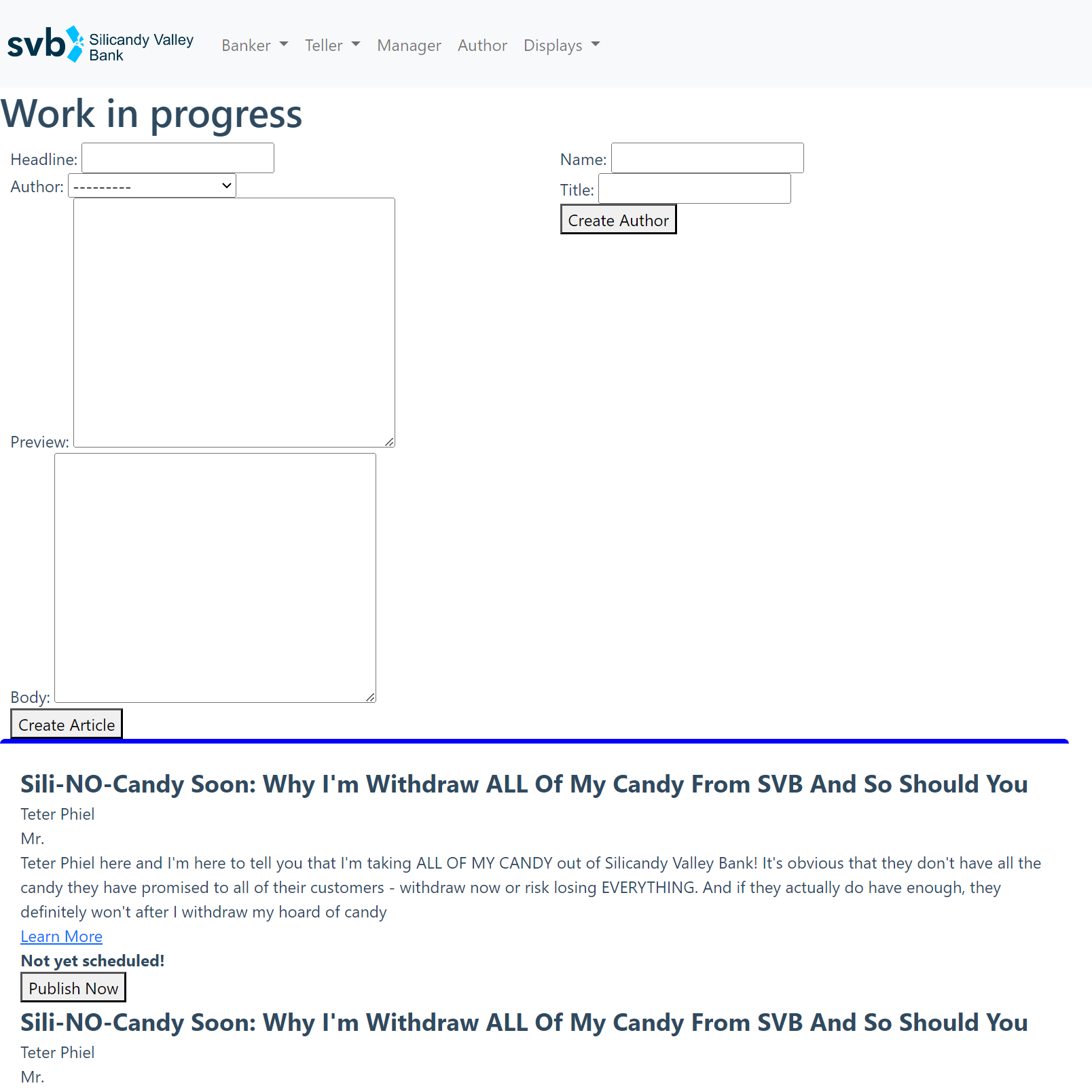
In addition, the internal website had a nifty interface for writing blog posts that would get posted to the website. Blog posts were categorized by level of panic, so they could be written en masse ahead of time and then rolled out in stages as the bank began to fail.
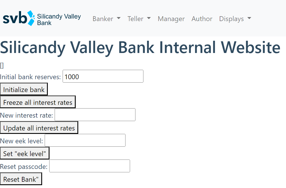
Interest rates and overall bank state were controlled from the “god mode” interface, allowing the bank to be initialized with an arbitrary amount of candy and tuned to collapse at a specific time by manually modifying interest rates to accommodate the rate of new account creation. A number of simulations were conducted to try predicting likely outcomes (time for the bank to run with various interest rates, incentive deposit amounts, and new account creation rates), which informed our initial incentive deposit amount and interest rate settings.
“God Mode” interface.Basic simulation with varying interest rates and initial deposits.
Interest accrual was calculated using a series of database entries we called “anchor events, which contained an account balance and timestamp. Each account would have an “anchor event” for when it was created (with its starting balance and interest rate), and for each subsequent modification to the account, be it an interest rate change, deposit, or withdrawal. Calculating an account’s current balance was done by pulling its latest anchor event from the database, and applying the anchor event’s interest rate to its anchor event balance using the continuously compounding interest formula.
Using this anchor event system allowed interest displays to be shown “live” with actively increasing numbers on the account view’s web frontend, with minimal load for the web server. Each live account view would poll the database for the latest account anchor event every 10 seconds or so, then use the anchor event parameters and the continuously compounding interest formula to create a lively scrolling numbers display. The hope was that seeing interest accrued in “real time” would encourage TOTs to keep their treats in the bank as long as possible to get the largest possible payout, thereby creating the correct incentive structure for a bank run when treats would begin to run out.
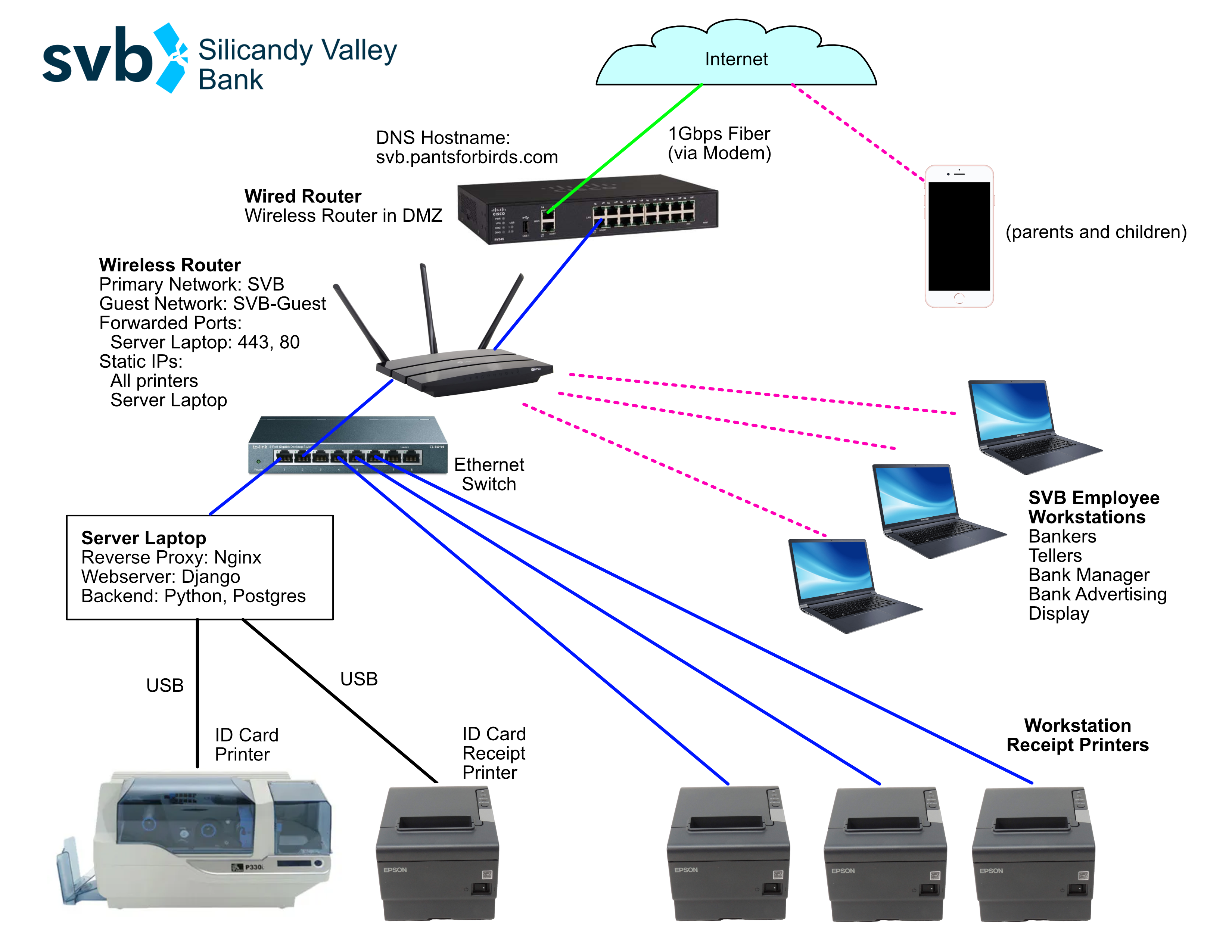
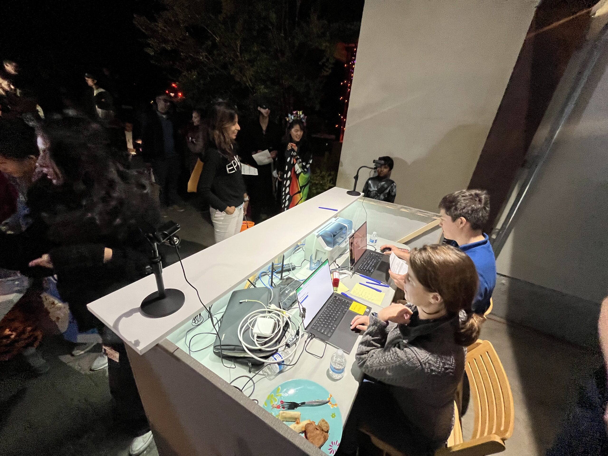
The website was run on an old Intel NUC as a series of docker containers, including containers for the Django webserver, PostgreSQL database, NginX reverse-proxy server, and SSL certbot (for installing HTTPS certificates). Once a DNS entry for the svb.pantsforbirds.com subdomain was set up with my domain registrar, getting the webserver port-forwarded through the network at my parents’ house was relatively straightforward.
Silicandy Valley Bank network diagram.
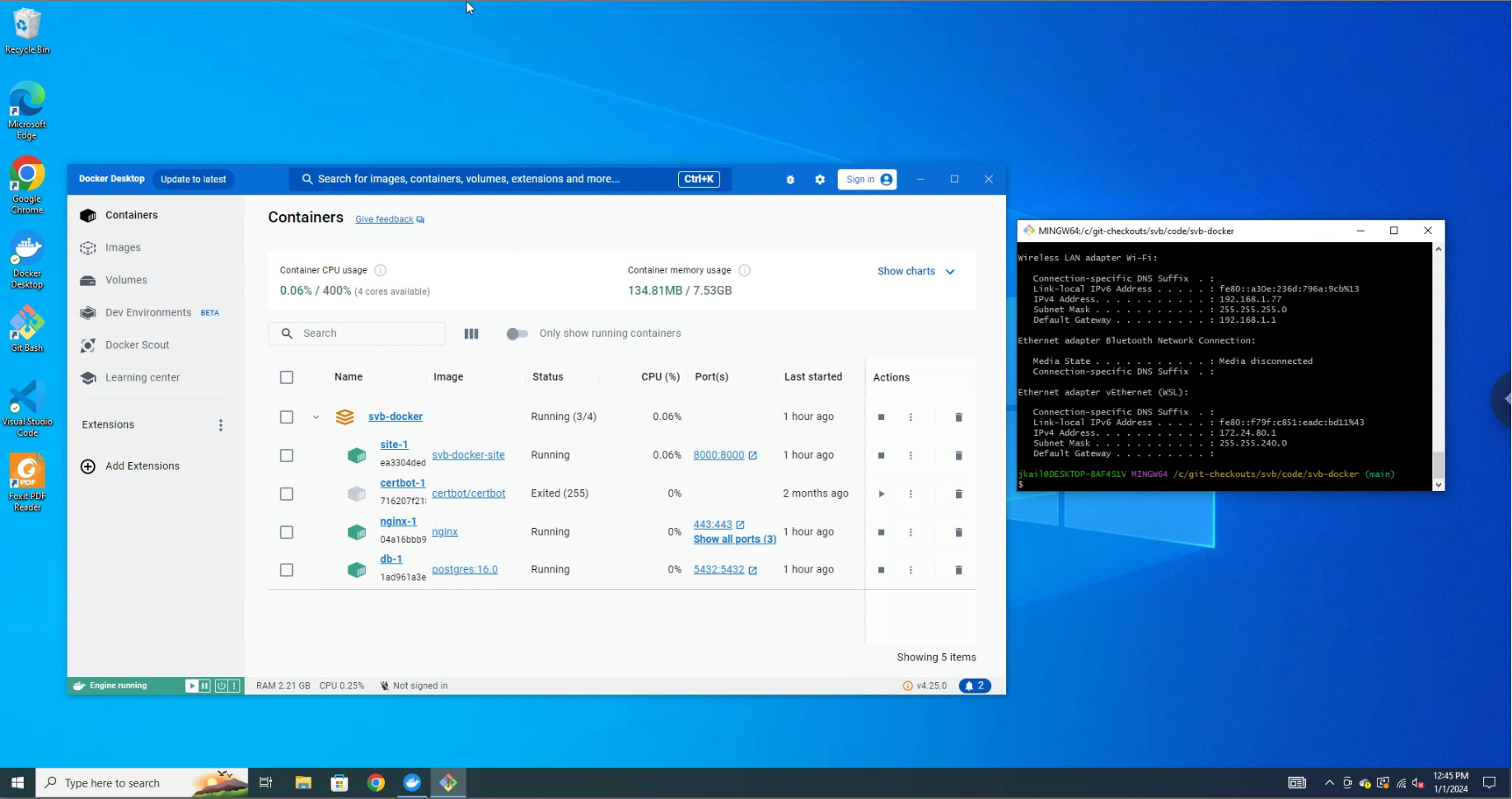
Regrettably, the NUC needed to run Windows in order to make use of the available printer drivers for the ID card printer, which was running off a direct USB connection (using its integrated 10 BASE-T Ethernet connection was excruciatingly slow). This prevented SSHing into the web server and made me miss a number of other Linux utilities, but was still the lowest-effort path to getting things up and running in a limited amount of time. Remote work on the server was conducted using Chrome Remote Desktop and Git Bash, which worked quite well for getting things deployed in the days before Halloween when we weren’t on site.
Since getting USB interfaced with a docker container is a royal pain in the butt, especially on Windows, ID card print jobs were run from a local poetry environment, which ran a python print script that pulled ID card print jobs from the PostgreSQL database and forwarded them over USB to the ID card printer using system calls to PDF reader software installed on the system. In theory, the PostgreSQL database could have been exposed to the local network and the ID card printer script could have been run on a separate Windows device, allowing the primary server to be a Linux machine, but the added complexity of this alternate configuration was undesirable.
Remote view of the webserver via Chrome Remote Desktop.
Dockerizing the website containers allowed volunteers to easily develop on their own machines without needing to install dependencies separately, which was hugely helpful for allowing features to be built in parallel. A custom backup utility was written to archive copies of the website database and static files, allowing developers to easily share copies of the website in various “states” (open accounts, blog posts, etc). This made parallel development much easier, and we’ll definitely be copying it for future web projects!
Piece 3: The Set
Just like for our DMV costume, the event took place in my parents’ driveway, which we did our best to tranform into a bank interior with potted plants, service counters, stanchions, and even a lighted “exit” sign. Two of our volunteers lugged over their gigantic ~100lb infotainment display, which we used to show bank statistics and B-roll promoting Silicandy Valley Bank.
We also set up a pop-up tent at the front of the driveway with a banner and some tables, as a good spot to explain the workings of the bank and help kids fill out their account application forms before getting in line. A significant amount of thought was put into optimizing the layout for organized queuing and adequate flow of trick-or-treaters, since we wanted everyone to be able to visit the bank in a timely manner while also being able to see the action. Special attention was paid to securing large or heavy props (like the infotainment screen) to make sure they wouldn’t pose a risk to kids in a potentially crowded situation.
The videos shown on the infotainment displays were made from a combination of stock video footage and B-roll shot in our garage the weekend before. We aimed for maximum cheese / cringe factor via an amalgamation of generic corporate video montages and some more ridiculous “disruptive advertising” flavored shots.
Bank employees were issued uniform polos that were constructed with many painstaking hours of cutting designs out of heat transfer vinyl and using a sublimation press to adhere them to polos. Trick-or-treating bags with the bank motto and logo were constructed with the same techniques. FBI-style windbreakers for the FTIC officers were lettered using adhesive-backed vinyl, since we wanted to reuse the windbreakers in a future year, and we thought it was pretty unlikely that we’d have another use for “FTIC” branded apparel.
A friendly SVB employee in his uniform.SVB bags. Lots of bags.FTIC windbreaker under construction.
Hundreds of debit cards were printed during the week before halloween, since we’d previously found that the color printing process for ID cards was the bottleneck of our DMV operation (printing a single color ID card requires five consecutive passes with the ID card machine’s print head, as it prints through Cyan, Magenta, Yellow, Black, and Overlay panels of its ribbon). In order to speed things up this year, we separated the customized information on the ID card to the backside, which was printed in monochrome black, and left only standardized decorative elements on the front, which could be printed in color in advance of the event. Naturally, in the course of printing our debit cards, we ran into all manner of issues with the ID card printer, which first needed to be completely disassembled to have its aging drive belt replaced, and then later began melting ribbons and printing inconsistently (apparently it’s really hard to do a uniform solid color fill as the background to an ID card, since it requires intense and even heat across the full length of the ribbon). With some struggles and fine-tuning the print parameters for the ID cards, we managed to get just under 400 full-color debit cards printed before the event.
Last but not least, we purchased a lot of candy. Silicandy Valley Bank consumed 11x 5.75lb bags of candy. In the spirit of making treats as fungible as possible, all candies were non-chocolate “Funhouse Treats” with approximately equivalent size, but varying flavors. Trick or treaters were allowed to pick the number of treats corresponding with their withdrawal amount from a bowl filled with candy, ensuring that candy flavors were depleted relatively uniformly, while children would still receive the flavors they generally preferred.
Halloween
On the day of Halloween, things were coming together, but just barely in time! I pulled an all-nighter debugging and integrating a few last modules into the website, and we spent most of the day on Halloween assembling the set and testing IT infrastructure.
Around 5pm, trick or treaters began to gather at the top of the driveway to fill out their account forms, and shortly after that we started registering new accounts on the internal site. This worked flawlessly for approximately two minutes, after which a primary key error in the database prevented any additional accounts from being registered.
What followed was approximately 20 minutes of frantic debugging, while trick or treaters waited patiently in an increasingly lengthy line. Fried all-nighter brain does not a smart programmer make, and despite a number of repair efforts, we were unable to resolve the primary key issue. Eventually, the good decision was made to fall back to a completely manual banking protocol, where children would be issued a debit card with their name and account creation timestamp scribbled on the back in Sharpie. Children could choose to withdraw their full balance upon account creation, or could return to collect their balance at a later time, at which point interest would be manually calculated from the timestamp on their card and a fixed interest rate.
SVB Bank Manager (bottom right) views the unfolding chaos.
Without the core bank infrastructure online, there wasn’t an easy way to track deposits or change interest rates dynamically, so we had to drop the plans of inciting a real bank run and instead settled for operating as a normal bank. We proceeded with pre-planned skits of the SVB “bank manager” having some choice interactions with officers from the Federal Treat Insurance Corporation (FTIC), and did our best to reward trick or treaters who kept their candy in the bank with large quantities of plastic-wrapped sugar when they came to make their withdrawals.
FTIC agents shutting down the bank after taking control from the bank manager.
Despite the technical difficulties, the event was a smashing success. 323 trick-or-treaters opened accounts with the bank, and amazingly, the majority of them chose to leave their candy savings in the bank to accrue interest! The core mechanics of our costume could be boiled down to the basic structure of a marshmallow experiment, and I was entertained to note that our number of participants was much larger than the participant groups of many of the largest studies combined.
Trick-or-treaters and parents seemed to quite enjoy the SVB customer experience, and I was greatly entertained by young trick or treaters lecturing their siblings and friends about the power of compound interest and the importance of opening a savings account (little kids are smart)! Some trick or treaters even brought their DTV Treat Licenses that they had been issued the previous year, and attempted to use them as identification when opening their accounts!
Software RCA: The Importance of Integration Tests, and the Spirit of Halloween
Weeks after Halloween, once the dust had settled, I fired up the docker containers one more time to figure out why our database had pooped itself during the event. I knew that it was most likely related to our custom primary key generation functions; generating primary keys manually for a Django database is generally considered a Bad Idea™, but our previous DTV costume had done so without issue.
The cause of the database failure turned out to be a combination of factors.
I re-used some code from the DTV costume for generating primary keys, but didn’t pay close attention to the fact that the DTV primary keys were being generated with a different structure. DTV Treat License keys were generated with a fixed prefix based on the date and branch number, followed by a strictly incrementing series of numbers. SVB debit card IDs were generated with a prefix based on the trick-or-treater’s information (first name and costume), followed by an incrementing number. Some of the code I had reused from the DTV project was saving Customer models before their primary key was customized, leading to duplicate entries in the database in the case that multiple bankers were trying to create a new Customer model at the same time.
Test cases never tested the scenario where multiple Customer creation events were interleaved, and manual testing generally involved single users testing against their local website, so there weren’t opportunities for the primary key race condition to occur.
Oops! This one line of code borked our whole IT system.
The primary key issue has since been fixed (in case anyone wants to reuse our codebase for something else), and we’ve learned a very valuable lesson about the value of integration testing and thorough test coverage!
Perhaps more importantly, the biggest lesson that we learned was the importance of structuring an experience-centered project like a large-scale Halloween costume around people, and not technology. Seeing our volunteers adapt to keep the show running despite the near-complete failure of our IT system was extremely heartening, and made me realize that the while the IT system provided some additional interactivity and fun features, it was by no means the heart of the costume. The real core of our Halloween project was the team of friends who decided to dedicate many tens of hours of their time towards building a memorable experience for hundreds of trick-or-treaters, and I’m very excited to see what we do next, with or without technology!
Resources
This project was open-source and its assets are free to use! Code, graphics, CAD models, etc are available in the github repository!
In the course of home-etching a bunch of PCBs, I’ve spent many hours hunched over my drill press squinting at tiny drill bits and trying to line them up with pads for vias and through holes. These pads can be quite small: the smallest rivets I use have a pad size / head diameter of just 0.9mm, and a drill bit size of 0.4mm. After doing this for a few years, I came to the conclusion that there must be a more ergonomic and accurate solution to this problem.
I had previously used a CNC mill to drill and route through-holes, but I wanted to avoid having to set up a computer with GCODE every time I wanted to pop a few holes in a PCB. Furthermore, the laser printer that I use to lay out traces and pads has scaling that is off by a few percent along one axis. This really isn’t an issue, as most of my PCBs are pretty small, and is only really noticeable as an extra-tight fit when I have pin headers of 20 pins or more. However, when this slight scaling error is integrated across a whole PCB or a panel, if a CNC mill doesn’t have its scaling adjusted to match, it could drill holes that are millimeters out of place compared to traces and pads. In order to avoid the effort having to calibrate multiple pieces of machinery to the same scale factor, I wanted a solution that could allow me to drill more accurate holes without the help of computer-controlled actuators.
Similar Solutions
I noticed that other homebrew PCB enthusiasts had created camera-assisted drill press designs that utilized cheap USB microscopes installed under dremel drill presses. One design even modified a drill press to drill from under the PCB in order to stop debris from falling on the camera lens! These designs seem to work great, but I had a few other design features that I wanted in my own drill press camera system.
No external PC required (standalone microscope, ideally with its own screen).
Removeable / no permanent modifications to my drill press (I often use it for woodworking and metalworking) in addition to PCB drilling.
HDMI output to drive an external display for a more detailed view.
Easily adaptable to fit multiple types of microscope cameras.
Drill Press Camera Design
Since I wanted my design to be removeable from the drill press, I decided against the classic option of mounting the camera directly under the drill bit, as this often requires a good deal of space below the drill press table and some permanent modifications to the drill press to mount the camera solidly. Instead, I opted for a periscope design, where the microscope camera would lay horizontally on top of the drill table, and a 45 degree mirror in front of the microscope camera would provide a view of the underside of the PCB.
Even better, with this design topology, I could use my old Andonstar ADSM201 HDMI microscope camera, and the screen would rest at a convenient viewing angle for me to look at while running the press!
Once I settled on the periscope layout for the microscope camera, the next task was finding a way to illuminate the bottom side of the PCBs being drilled in a manner that wouldn’t introduce glare to the microscope lens. To do this, I positioned two high-density strips of RGBW LEDs on either side of the microscope lens. These LEDs are individually addressable over a one-wire interface, and have an extra dedicated white LED in addition to the usual RGB LEDs found on similar WS2812B LED modules. The extra white LED is quite bright, and very helpful when attempting to cram the maximum amount of lumens into a smallish space like I was with this project. The color and brightness of the LEDs is controlled by a Pi Pico that reads two potentiometers positioned at the back of the mirror enclosure. White light is ideal for maximum brightness, and provides good illumination for most PCB drilling applications. Other colors of light can be helpful for providing increased contrast when drilling colored substrates or looking for particular colors of fiducials.
The electronics of the microscope camera are powered by a PCB housed in the back of the mirror box, creatively named the “main board”. The main board includes a 5V 4.5A buck converter capable of powering the onboard LEDs, 2x USB devices (intended for the microscope camera an a small external display), as well as the onboard Pi Pico microcontroller. In addition, the main board also provides an extra +12V output in case a microscope camera with a 12V power input is used. Color and brightness control potentiometers are installed directly onto the main board, and can be accessed from the rear of the mirror box enclosure. The whole shebang (main board, microscope camera, external display) can be powered by a single 12V 3A power adapter that plugs into the back of the main board via a 5.5mm barrel jack.
The camera assembly is fastened to the drill press with some strong magnets. I’ve found that when running at high RPMs, vibrations can cause the assembly to shift slightly, but the addition of a high-friction layer between the magnets and the drill press table (in the form of something as simple as a latex glove) seems to be enough to stop the assembly from moving. I’m planning to modify the bottom cover of the camera assembly to add some M5 thumb screws to properly clamp it through the bottom of the drill table.
The bottom of the PCB being drilled is supported on a circular piece of glass with a 16mm hole drilled through the center. This transparent glass piece allows the underside of the PCB to be illuminated and viewed by the microscope, and the hole at its center ensures that it won’t interfere with a drill bit passing through the PCB, as long as the mirror box is properly aligned with the drill bit. There is an opening in the bottom of the mirror box enclosure just below the angled mirror in front of the microscope lens. Any fiberglass or copper shavings that drop through the hole in the glass circle can be blown out the bottom of the mirror box with a quick puff of air applied in the direction of the hole. Most shavings that land on the periscope mirror are out of the focal plane of the microscope camera, so they generally just show up as a slight blur. As such, frequent cleaning isn’t strictly necessary, but does help improve image quality. More extensive cleaning of the periscope mirror can be completed by removing the circular glass pane, or by unscrewing the top of the mirror box enclosure.
Initial tests of the drill press camera showed the field of view of the microscope to be a circle with an approximate diameter of 16mm at the bottom plane of the PCB. This means that the hole drilled in the center of the glass circle is about enough to cover the full field of view of the microscope, so the transparent glass circle isn’t entirely necessary. The glass circle could quite easily be replaced with a 3D-printed plastic circle with a 16mm hole in the middle, with no real impact to the microscope’s field of view.
Usage Instructions
Using the drill press camera is quite simple! My general worflow goes something like this:
Install mirror box assembly onto drill table with magnets. Throw a latex glove under the magnets for good luck (and better resistance to movement while the drill press is vibrating).
Plug in the mirror box main board to power, and connect the microscope camera and optional external screen to the main board via USB.
Bring the drill bit down to the focal plane of the microscope camera. Mark the position of the center of the drill bit on the screen, either using an electronic crosshair setting (available on some microscope cameras) or a washable fine-tipped marker (I use a vis-a-vis marker on the plastic cover of my microscope camera’s screen). If your screen doesn’t have a plastic cover, I recommend using a projector transparency to mark the crosshairs onto instead of drawing directly on the the surface of the screen.
Set the LED brightness and color as desired for best visibility of your PCB and its drill features.
Place the PCB to be drilled on top of the mirror box’s glass circle, with drill marks on the bottom side.
Use the crosshairs on the screen to line up your drill bit with the points you want to drill.
Happy drilling!
PCB drill bit being aligned with crosshairs on microscope screen.Drill press camera being used to drill 0.4mm holes in a PCB.
Project Files
CAD models, MicroPython code (for the Pi Pico), and gerber files (for the PCB) are available on this project’s github repo.
ALTERNATIVE PART if you have an external display and want higher resolution and crosshair functionality. You will need to make some new camera mounting brackets with a slightly larger diameter, but everything else should work fine.
My most recent design challenge was building a remote load switch for a hypothetical aerospace application. I formed and documented a design through schematic capture, simulation, and hardware layout, but stopped short of routing the PCB and sending things out on an initial prototype run. The simulations look good and most of the design is similar to some circuits I’ve used successfully in the past, so I’m around 75% sure that it would work on the first pass (after fixing the odd issue with a bodge here and there). Still, the design is neat to look at, so I figured I would leave a documentation nugget here for future posterity.
The Challenge
The design challenge tasked me with building a remote-controlled DC load switch capable of 12-60VDC operation, switching up to 10A to a moderately inductive load. The switch would need to be controlled and current monitored via an interface to a remote computer up to 100ft away. Additional design considerations included EMI, temperature ratings, protection (undervoltage / overvoltage / overcurrent), support for capacitive loads with high inrush, galvanic isolation of power and communications circuits, and fail-safe behavior.
A complete explanation of the design challenge and my solution to the problem are included in the design notes document below. Features of the final design include:
High side PMOS switch with discrete drive circuitry (compatible with wide supply voltage range).
Reverse polarity protection.
Pseudo circuit-breaker overcurrent protection (separate protection systems for short circuit and thermal overcurrent events).
Undervoltage protection.
Overvoltage protection.
EMI filtering for enhanced noise immunity and reduced noise emissions.
Current monitoring with 10mA resolution.
Galvanically isolated differential serial communication link.
Since using some of the parts in this design for other designs, I’ve found that the MCP6542 comparator has a bit of a slower propagation time (8us) than what’s needed for overcurrent protection. I would recommend comparators like the MCP6556 (80ns) or the LMV331 (500ns) for this design.
I recently came upon design challenge for designing a single-cell battery simulator. I started having a lot of fun with the project–by the time it was done, I figured it was worth documenting as a good example of my hardware and software design workflow. As of the time of writing this post, I’m quite happy with what I made, but I’m hoping that in a few years I can look back at this post in a “look at how far I’ve come!” kinda way. We’ll see! Here’s to learning new things in the future.
The Challenge
The following text in italics is taken from the challenge. Some unimportant details are removed for clarity.
Battery management system (BMS) is one of the critical systems used in electric aircraft to monitor the status and the health of the battery. To test the performance of the BMS, a battery simulator is needed.
As shown in the following figure, the designed simulator is controlled by an MCU and it communicates with a computer via serial communication. The cell voltage can be set from the computer. The balancing current can be supplied, measured and reported to the computer by the simulator.
An isolated 5 VDC voltage source is given.
The cell voltage can be adjusted in the range of 2.5 V to 4.5 V via MCU with tolerance of ±5%.
The simulator can supply and measure the balancing current (current flowing out of the simulated cell) up to 200 mA with tolerance of ±10%.
What I Made
The challenge really only asked for a rough schematic, but I had a strong hankering for a good analog project and hadn’t touched my op amp drawers for too many months, so I got working on a circuit that I could build with what I had available in the workshop.
After considering various topologies based on linear regulator ICs (not enough headroom) or switching power supplies (didn’t have the chips on hand), I decided that one of the easiest ways to tackle the battery simulator challenge was to build what is essentially a juiced-up op-amp. The circuit would use a generic rail-to-rail op-amp for control, but would drop unwanted voltage from the 5V supply using an external power BJT and an associated drive circuit. While not very energy efficient, this circuit looked like it could be pretty simple and cheap to build, and would meet the relatively modest power requirements of the challenge quite easily. An added bonus was that by using a dual rail-to-rail op amp, I could dedicate the unused op amp circuit to high side current sensing! For compute, I used a Pi PIco since it was readily available, cheap, and I had already built out a docker environment for programming and testing for the RP2040 as a target.
During my design of the battery cell simulator, I added some opto-isolators to allow multiple battery cells to be chained together. I became very curious about whether my design for daisy-chaining cells into a simulated battery pack would work, and decided to build out the motherboard that would allow multiple battery cells to be supplied with isolated 5V power and daisy-chained such that they could communicate with each other and their output voltages would be presented in series. I designed the motherboard such that each of the battery cell circuits could be inserted as a vertical card, and created a 3D-printed enclosure to house the motherboard and all of its installed cards. I bootstrapped an indicator LED for each cell by heat-forming a PMMA optical fiber into a light pipe and affixing one fiber over each Pi Pico’s status LED.
The full design process, stream-of-consciousness debugging and all, is recorded in my design notebook document. Some quick links:
I documented the completed devices at the multi-cell (Cellsim 4S) and single-cell (SCBS-Pico) levels to capture things before they sublimated from my brain and to dust off the technical documentation skills. There’s something satisfying about writing datasheets!
As of the time of writing this post, I’ve been chasing the dream of etching circuit boards at home for at least four years. After flopping around between various techniques for years (including CNC milling with two separate machines and lots of mods), I think that I’ve finally settled on a techniqe that is low cost, reliable, and fast enough that it can compete with hand-soldered prototypes in many scenarios.
What I want in a home PCB fabrication solution:
Fast: Should be faster than hand-soldering a circuit if I need more than one copy, including time required for schematic capture / layout / etc.
Cheap: Should cost under $5/PCB in raw materials.
Consistent: Needs to have process yield well above 80-90%. If I’m etching a PCB and not buying it, usually it means that I need ultra quick-turn and can’t sit a round to futz with the process until it works.
To Mill, or to Etch?
My initial attempts at PCB fabrication relied on CNC milling, which I attempted with a rather floppy CNC router intended for woodworking (Millwright M3) and later a custom modified 1610 CNC Mill from Amazon. I experimented with many varieties of v-shaped engraving bits and even some fine-tipped router bits, but was never able to achieve perfect consistency in trace isolation, even after doing my best to stiffen up the machines, reduce runout, and implement high resolution mesh surface levelling using bCNC. In the end, after many broken bits, and many more crappy and inconsistent PCBs, I abandoned CNC milling in favor of chemical etching, which turned out to be much cheaper, more consistent, and much faster (4 minutes to etch a complex board vs 40min+ to mill it board).
CNC Milling has many tempting features up front, including the apparent process simplicity, but in my experience it ultimately lost out to Chemical Etching as the more effective process for PCB fabrication. Some reasons why are included in the table below.
No, but you will spray FR4 and copper dust everywhere. You can control it by milling under mineral oil, but that gets incredibly gross very quickly (just ask my mutilated shop vac hose that will forever be filled with copper / fiberglass / mineral oil dust goo).
Yes. Ferric Chloride. OOooo scary (not actually that bad if you follow proper safety precautions). One batch of Ferric Chloride will last you for many years of hobbyist etching, so not a frequently replaced item.
Consumable Materials
– Copper-clad PCB blanks – Drill bits
– Thermal transfer paper – Copper-clad PCB blanks – Kapton tape – Toner reactive foil – Drill bits
Reliability
Low It’s very difficult to get the PCB surface exactly level, and since the copper-clad layer is so thin (~30um), it’s very easy to end up not fully milling some traces unless the PCB is milled at a large depth. If using a v-bit, a large milling depth results in large gaps between traces, reducing design flexibility.
Medium-High Very tight trace/space fabrications are possible (I’ve gotten down to 0.2mm clearance between traces), but process reliability heavily relies on some key details that determine the results of the thermal transfer and PCB etch steps (surface treatment, etchant temperature, mask sealing, etc). Full test still recommended, some boards may need to be touched up with some solder or have traces separated with an X-acto knife.
Time to Etch One PCB
10-40+ minutes Depending on complexity (machine needs to mill out each trace individually).
~4 minutes All traces are etced simultaneously. Etch time may need to be extended if a large volume of copper is removed, but shouldn’t need more than around 10 minutes with well heated and agitated etchant.
Time to Etch N PCBs
N*(10-40+ minutes) More PCBs means more traces to mill. Not much benefit is had when scaling up to more copies of the same PCB.
~4 minutes Etching a panel takes only marginally longer than etching a single board (you’re limited only by the etch rate of the Ferric Chloride solution).
Minimum Trace / Space Achieved by John
0.4mm/0.4mm
0.2mm/0.2mm
The John McNelly PCB Etch Processâ„¢
My PCB etching process draws heavily from what electronics hobbyists have been doing in their garage for many decades, but I figured that it would be nice to share my list of materials and specific techniques in order to flatten the learning curve a bit for anyone else looking to try out etching PCBs at home. Links in the tables below are Amazon Affiliate links to products that I have personally used (or as close a substitute as I can find if the original listing is no longer available). All proceeds go to the Fun Project Fund!
Equipment List
Equipment Item
Description
Etch Tank
I use this etch tank kit from Circuit Specialists. It includes an etch tank, air bubble agitator, and heater. Note that the plastic clips that come with this kit will disintegrate in short order in Ferric Chloride, so I always drill a hole through my PCB and thread some stiff plastic-coated wire through that to use while etcing. I put the heater and pump onto some switched electrical plugs so that I can keep them off whenever the system is not in use.
Laser Printer
There is some debate about what printer is best for this process, but helpful resources exist from providers of off-the-shelf PCB etching kits. There are some rumors that Brother printers don’t work well for the toner transfer process, but I’ve had good luck with mine (DCP-L2540DW) in the process described in this page. It’s important to use a genuine toner cartridge for printing mask layers, since resolution and perfect coverage make a big difference. I use a genuine Brother TN660 toner cartridge. Note that this only works with monochrome laser printers, not color laser printers!
Thermal Laminator
A good temperature-controlled thermal laminator is essential for getting toner to properly transfer onto the PCB blanks. You will need something with enough heat output to bring a PCB blank up to temperature (copper is a fantastic heatsink), spring-loaded rollers that can widen enough to accommodate a PCB (1.6mm thickness), and a high enough maximum temperature that it can allow toner to re-fuse properly. I bought a Tamerica TCC330 pouch laminator for this job and it works great. I use it with the temperature setting cranked all the way up and still need to do 6+ lamination passes on a PCB to make sure that it’s evenly heated.
Having a pouch laminator is also nice for non PCB-reasons, since you can always us it to, like, laminate stuff. I’ve used mine to laminate labels for industrial electronic equipment, laminate menu board signs for a farmers’ market stand, and toner transfer decorative foil onto custom letterhead as a gift for a friend! If getting a laminator seems too extra, other hobbyists have had good luck using clothes irons, and I’ve considered using one of the heat presses intended for application of vinyl stickers onto t-shirts but haven’t had a chance to try it out yet.
Shear Brake
I’ve found that by far the easiest, cleanest, and most reliable method of cutting FR4 PCBs is by using a mini benchtop shear brake. The shear brake’s clean shearing action allows you to easily cut PCBs down straight lines with minimal kerf, allowing clean separation of closely spaced panels and preventing the generation of potentially nasty FR4 dust. A sheared PCB edge looks very similar to an edge cut using a v-groove cutting wheel, in that it looks slightly “hairy” with some exposed FR4 fibers. Running the freshly cut edge of a PCB across some sand paper cleans things up quite nicely!
I don’t recommend using a shear brake on multi-layer PCBs where there is a risk of deforming the board and crushing internal structures like vias, but it works great on single-sided boards (or multilayer boards that you don’t care much about). In addition to depanelizing my homebrew PCBs, I use my shear brake to cut protoboard down to custom sizes, and also to cut plain FR4 into shapes for use in other projects. I also use my shear brake to cut and bend brackets out of aluminum sheet metal, which has come in handy a few times!
Drill Press
A good drill press is essential for drilling vias and through holes on home-etched PCBs. Many of the drill bits necessary for component through holes have a very fine diameter (<1mm), so drilling them with a handheld drill is very difficult. Fortunately, there’s no need for a huge drill press here, and reasonably priced benchtop models exist with sub-0.1mm runout! I bought an 8-inch benchtop drill press on Amazon a few years ago and have used it to drill many many holes in homebrew PCBs, from 6mm diameter all the way down to ~0.4mm. It’s also come in handy for woodworking and light metalworking on many occasions.
Since many of the PCB drill bits are intended for use at high RPMs and plunge rates, I configure the belts to run the drill bit at the maximum possible speed (~3000rpm). I highly recommend using a thin piece of wood as a spoil board when drilling PCBs to minimize the risk of hitting the drill press base plate or blowing out the bottom of the PCB (for larger holes).
Good alignment of the drill bit to the hole drill position is essential for good results. Newer and fancier drill presses can be found with adjustable laser crosshairs that might assist with accuracy, but I’ve been able to get “good enough” results with a carefully calibrated eyeball and the assistance of a magnetic sewing machine light stuck to the side of my drill press.
Paper Cutter
Scissors work just fine, but I have enjoyed using a paper cutter to shave off a few extra seconds of cutting thermal transfer paper and toner reactive foil to size.
Secondary Chemical Container
Having a secondary container for your etching workbench is a really good idea, as it helps protect against inevitable spills (ferric chloride stains everything, acetone is nasty, liquid tin smells like farts, etc). Through some obvious but unwritten laws of probability, it is widely understood that a workbench that is well prepared for a chemical spill will never have one, but a workbench cluttered with valuable items and unprotected against a chemical spill will breed frequent catastrophes (particularly if it’s being used unprotected “just this once”). Anyways, I found that these silicone mats for protecting the cabinets under kitchen sinks work really well as secondary containers.
Materials List
Consumable Item
Description
Thermal Transfer Paper
I use generic yellow thermal transfer paper from Amazon. It runs about $20 for 100 sheets, and I cut the sheets into small PCB-sized sections and tape it onto printer paper with Kapton tape, so I usually can get well more than one PCB out of a single page of transfer paper.
Toner Reactive Foil
Toner Reactive Foil (TRF) aka “Toner Fusing Foil” is a thin plastic film that bonds to printed toner when heated in a thermal laminator. It is used in the etch mask sealing step for PCB fabrication, but comes in a variety of colors (including shiny ones), and can be used for greeting cards, stationery, etc with foil patterns.
TRFs are available in a wide variety of colors, from craft stores (e.g. Minc brand) or commercial printing suppliers. I usually use white TRF for my etch process, but other colors should work just as well.
Copper-Clad PCB Blanks
There are a number of good vendors of copper-clad FR4 PCB blanks on eBay and Amazon, but I’ve had especially good luck with PCBs from Paramount CCL, as they’ve always been consistent in dimensions and quality, arrive well-packaged, and show up clean and shiny. I’ve also had very good luck soldering with their boards, as the copper cladding is well bonded to the substrate and survives reflow and rework operations without issue (I work with leaded Sn63Pb37 solder).
Single-Sided PCBs – 4x3in (good for small projects) – 4x6in (good for medium projects or panels)
Double-Sided PCBs – 4x3in (good for small projects)
Kapton Tape
Kapton tape’s chemical-proof, heat-resistant, and residue-free properties make it extremely useful in just about all parts of the PCB etch process. I use Kapton to secure thermal transfer paper fragments to copy paper for printing the toner mask with a laser printer, for holding thermal transfer paper to PCB blanks during lamination, and for masking off portions of copper that I don’t want to be removed during the chemical etch process. It’s also very useful for heat-shielding various components during hot air rework.
Brand-name Kapton tape is pretty pricey, but I’ve found that many of the generic brands on Amazon labelled as “Polyimide Tape” work just as well. I use 0.75in Polyimide Tape for most purposes, and 3in Polyimide Tape for masking entire faces of 4x3in PCBs (for instance, if I want to have a ground plane on the non-etched side of my PCB).
Fine-Grit Sanding Sponge
I use a fine grit sanding sponge to lightly abrade the surface of a fresh copper-clad PCB blank in order to provide a better surface for the thermally transferred toner to bond to. Anything in the ballpark of 200 grit should be OK.
Kimwipes
Kimwipes are lightly abrasive cleaning wipes that are perfect for preparing copper PCB blanks for thermal transfer after light sanding (I give things a thorough cleaning with a wipe soaked in isopropyl alcohol). Kimwipes are also useful for generic cleaning tasks around the lab; some wipes and a pump dispenser bottle filled with 70% IPA is a match made in EE heaven.
Isopropyl Alcohol
I use Isopropyl Alcohol (IPA) to remove any surface coatings and contaminants from the fresh PCB blanks before the thermal transfer process. Small amounts of grease / anti-oxidation coatings / whatever can make it hard for the thermally transferred toner to stick to the copper properly. I recommend using ~70% IPA so that you have a good chance of removing contaminants that are soluble in either alcohol or water (I’ve found that 70% IPA often cleans better than 99%, for instance).
Acetone
The nasty stuff. Use in a well-ventilated area and keep away from children and burny things. This is used to remove the toner mask and toner reactive foil after chemical etching is complete. I’ve had good luck sourcing acetone from my local Home Depot, and use it with blue shop towels to scrub down PCBs and remove etch mask residue.
PCB Drill Bits
Good drill bits for PCB via and hole drilling are different from most drill bits found in Home Depot, as they are manufactured from carbide (fiberglass can be very abrasive) and have a necked-down portion of the shaft where the standard 1/8″ shaft transitions to the much smaller diameter cutting body. Most high quality drill bits will also include a color-coded collet that indicates their diameter and allows them to be easily indexed into a drill collet with a consistent tip position.
There are a large number of low-quality drill bits available that are made with low quality materials like high speed steel, but carbide drill bits from reputable manufacturers like Kyocera are available used and new for very reasonable prices. My favorite vendor is drillman1 (now Oliver Tool Company) on eBay, who specializes in selling high quality PCB drill bits.
My standard set of micro drill bit sizes is included in the list below. I always recommend getting extra drill bits, especially of the smaller sizes, as they break pretty easily.
I use laminating pouch carriers to protect toner reactive foil from getting sucked into the rollers during the etch mask sealing thermal lamination step. I do not recommend using them during the toner thermal transfer operation as they significantly slow the heat transfer, but they are very useful for managing thin and finicky foils like TRF. These are available from commercial suppliers or from Amazon. DIY versions can be made by folding a piece of heavyweight paper in half, but lack the interior silicone coating that stops adhesives from sticking. I usually cut my pouch carriers down in length so that they are more closely matched to the size of my PCB blanks, to avoid waiting extra time for the whole pouch carrier to go through the rollers during every lamination cycle.
Step 1: Etch Mask Thermal Transfer
The first step in the PCB fabrication process is transferring a mask of what we dont want to etch onto our copper-clad PCB blank. This is done by thermally transferring toner from a laser printer using the steps below.
Print front copper and edge cuts layers onto a piece of copy paper, with the following parameters:
If printing the primary (front) side of the board, the mask must be mirrored. This is because the mask will be reversed when it is thermal-transferred onto the PCB blank; the top side of the copy paper is like the adhesive side of a sticker that will be transferred to the PCB. If printing the secondary (back) side of the board, the mask must not be mirrored, since the EDA software generates plots looking down through the primary side of the board.
Use 1:1 scale and center the mask pattern on the copy paper.
Set drill holes to be printed as a “small mark” so that the hole doesn’t end up oblong if the drill bit isn’t perfectly centered.
Mark the end of the page that came out of the printer first with a small arrow in ballpoint pen or sharpie. This indicates your feed direction, and is important for later!
Verify the mask is in the correct orientation (mirrored or not mirrored). The easiest way to check this is to add lettering to the copper (REV letter, PCB name, etc) and check the orientation of the text after printing.
Verify the mask scaling in X and Y with calipers using the edge cuts or other prominent PCB features. It’s best to measure the longest known X or Y dimension you can verify in order to make sure scaling on the printer and printer driver is correct. Use printer drivers directly from the manufacturer if available (auto-installed Microsoft CUPS drivers often mangle scaling in unintuitive ways–I’ve had things print at 95% scale and only realized it when components didn’t fit)!
Cut a rectangle of thermal transfer paper slightly larger than the mask pattern and position it above the mask pattern printed onto the copy paper. Mount the transfer paper shiny side up to the copy paper with a piece of Kapton tape along the transfer paper edge closer to the feed direction symbol you drew in step (2). Make sure that the Kapton tape completely covers the edge of the leading edge of the transfer paper and has no wrinkles!
Thoroughly wipe down the thermal transfer paper with a fresh Kimwipe. This removes any dust and is essential for slightly roughening the surface to get the toner to stick better. If this step is skipped, there is a high probability of parts of the mask rubbing off of the thermal transfer paper as you align it to the PCB, causing traces to be broken or shifted!
Feed the copy paper into your printer, feed-direction symbol first. If your printer has a slot for inserting envelopes or other specialty papers that don’t fit into the standard size paper tray, I’ve found that it makes this step much more convenient, since you won’t have to constantly open and close the paper tray, and the paper can be inserted into the slot print-side-up.
Print the mask pattern onto the thermal transfer paper. Use the darkest toner setting your printer has, and use a thicker paper setting in order to make sure that the toner has enough heat to properly fuse to the thermal transfer paper. These settings are usually available through the printer driver if using a proper driver provided by the printer manufacturer.
Remove the thermal transfer paper with the printed mask pattern from the copy paper backing. Make sure that no part of the pattern was accidentally printed on the Kapton tape or missed the thermal transfer paper and ended up on the copy paper backing!
Prepare a PCB blank for thermal transfer by lightly sanding it with a fine (>=200) grit sanding sponge to rough up the surface, and then cleaning it thoroughly with a Kimwipe dampened with 70% isopropyl alcohol. This will create more surface area for the toner to bond to, and will remove sanding residue and other contaminants that could prevent the toner from creating a good bond with the surface of the copper plating.
Fasten the thermal transfer paper to the PCB blank with Kapton tape, with the toner side against the copper plating. Ensure that the Kapton tape does not overlap any portion of the thermal transfer paper with toner mask, as this could inhibit the thermal transfer process.
Set the laminator to maximum temperature, and feed in the PCB blank with attached thermal transfer paper. Alternate which section of the laminator you use, and alternate copper side up / down orientation (if board is single sided) in order to not cool down one section of the rollers too much. Run the PCB blank through the laminator ~6 times or until the toner has fused completely to the copper plating on the PCB blank.
Remove the thermal transfer paper backing from the PCB blank. If this does not remove cleanly, you can soak the PCB blank in water and gently scrub away the paper backing.
Once thermal transfer is complete, you should end up with something like this:
Step 2: Etch Mask Sealing
Even when the toner is printed at maximum darkness, there are still teeny gaps in many of the solidly filled areas. Etching a PCB with a pure toner etch mask will result in traces and floods having a “speckled” appearance, which under a microscope can be seen as a very large number of small holes in the copper resulting from etchant finding its way through gaps in the toner mask. One common solution to this would be to run the mask through the printer multiple times to lay down another coat of toner, but the indexing of the paper to the print head is very low precision and the mask wouldn’t overlap itself precisely. A better solution is to seal the toner with a solid layer of Toner Reactive Film (TRF). TRFs are thin films designed to bond to toner particles when heated, and are often used for decorating greeting cards or stationery. Greeting cards with gold foil designs are usually made by printing the foil design in toner, and then laminating a layer of gold foil TRF to the toner pattern. TRFs are available in commercial flavors as well as DIY arts and crafts flavors (Michael’s and other craft stores carry TRFs under the Minc brand). TRFs come in a variety of colors, but for the purposes of chemical etching, they all work just fine. I generally use white TRF since it’s cheap and widely available, and could be used for white silkscreen if I use green soldermask over my copper traces.
Cut a section of TRF large enough to cover the thermal transferred toner pattern on the PCB blank.
Align the TRF over the toner pattern, with the dull side of the TRF against the copper. Place the TRF and PCB blank into a lamination carrier.
Set the laminator to maximum temperature. Pass the lamination carrier through the laminator ~3 times (or until TRF is completely fused) leading with the carrier seam, alternating roller location and up / down orientation for even heating.
Peel back the TRF plastic backing to reveal the TRF bonded to toner. All sections of toner should be completely covered with TRF.
This is what a PCB with a sealed etch mask pattern looks like before etching.
Step 3: Etching
Once the etch mask has been sealed, it’s time to remove all of the non-masked copper from the PCB! I’ve found that Ferric Chloride works great for this and is widely available, but other chemical solutions exist to do the same thing. Etch speed is heavily dependent on temperature, agitation, and etchant/copper concentration, so it can be difficult to get a consistent etch if these factors vary across the surface of the PCB. Some hobbyists etch their boards in glass Tupperware filled with a thin layer of Ferric Chloride that they slosh back and forth by tipping the Tupperware container, but this can take 20-45 minutes to get a complete etch. If the etch rate varies across the board, some traces in faster-etching portions can be over-etched due to their exposed copper sides getting eaten from under the sealed mask layer. It’s best to have a fast, consistent etch and remove the board as soon as etching is complete. Some hobbyists experiment with fancy spray-etching machines and different solutions, but I’ve found that a vertical etch tank kit with a heater and an aquarium bubbler has worked great for my purposes. These kits take a lot of etchant (2 liters), but that amount of etchant can be used for many many PCBs. I’ve used the same etchant solution for over 2 years–etch times have extended slightly as the solution gets saturated with copper, but this has not created any issues for me.
Fill the etch tank to the required level. If the etch tank was previously filled and has had its fluid level lowered due to evaporation, top it off with distilled water and stir thoroughly.
Plug in the etch tank heater and allow the solution to get up to an even temperature (stir gently if required). You can tell that the solution has reached its proper temperature when the heater shuts off (stops glowing).
Drill a hole for a wire hanger onto the PCB blank, outside the bounds of the PCB design (or better yet, use a mounting hole within the PCB design for this purpose).
Mask off any additional (non toner-sealed) copper that you would like to preserve using Kapton tape. Ensure that there are no bubbles or wrinkles around the edges that could allow etchant solution to creep underneath.
Activate the aquarium bubbler to begin agitating the etchant solution.
Mount the PCB blank to a plastic-coated wire hanger and lower it into the etchant solution. Make sure that the PCB isn’t sucked up against the sidewall of the container on the copper side, as this will inhibit the etch process.
Check on the PCB periodically and remove it from the etchant solution as soon as all exposed copper has been etched away. Rinse the PCB under clean water to stop the etch.
Soak a shop towel in Acetone and slowly but firmly scrub the PCB to remove the toner and TRF etch mask. You should be left with shiny copper and clean-looking FR4 where the copper was removed. If you have black toner smears on the FR4, add more acetone and scrub again, allowing ample time for the acetone to penetrate the etch mask layer.
This is what an etched PCB looks like. Note the black toner smears (I didn’t scrub properly when removing the etch mask layer).
Step 4: Plating (Optional)
If this PCB is intended for long-term use and you are concerned about copper oxidation for aesthetic purposes, or if you have concerns about copper oxidation inhibiting solderability after reflow, you can tin-plate the traces using a liquid tin solution. This takes just a few minutes, but I usually don’t bother as the vast majority of the PCBs that I manually etch are usually ultra quick-turn prototypes that will be used for testing and then replaced with a properly fabricated design.
If tin plating isn’t your cup of tea, you can mimic a HASL finish by going over each trace with a blob of solder on a soldering iron. This leads to a slightly uneven surface finish that can make soldering surface mount parts problematic, but works just fine for most applications.
Place the etched PCB into a glass Tupperware filled with a thin layer of liquid tin solution (enough to cover the PCB). Agitate the PCB and solution with a silicone brush.
Once the PCB is completely plated (or you have waited the proper length of time based on the liquid tin solution instructions), remove the PCB from the liquid tin solution and rinse it under clean water.
Example of a tin plated PCB.
Step 5: Drilling
I find that it’s easiest to perform all drilling immediately after etching and when the PCBs are still panelized in order to increase surface area for handling the PCB (it’s hard to hold a very small PCB down while drilling it), and to allow through holes to be used for indexing silkscreen to the board in step (6).
Drill out the holes marked on the PCB’s etch mask using the drill size indicated on the PCB drill map (or the next available larger drill bit size).
If making a 1.5-sided board (etched copper on one side, solid ground plane on the other side), use a large drill bit (~3mm) to counter-sink any non-grounded holes on the ground plane side. This will prevent the leads of through hole components from shorting to the ground plane when this is not desired. The counter-sink should just deep enough to go through the copper layer but not too deep into the FR4.
Example of a partially assembled 1.5-sided board. Note the isolation holes around non-grounded through holes (see unpopulated trimmer pot footprint in top left).
Step 6: Silkscreen (Legend)
Adding a silkscreen (aka. Legend) layer to the etched PCB is extremely helpful for labelling components with reference designators, indicating component polarities, and labelling pins and testpoints. I usually use a simple toner silkscreen layer, and have found that it adheres best to bare FR4 and solid copper floods. Silkscreen items that need to be printed over narrow copper traces often don’t transfer properly, as the variations in altitude between the tops of the copper traces and the face of the FR4 substrate cause the thermal lamination process to be incomplete, leaving fragments of silkscreen stuck to the thermal transfer paper instead of the PCB. A winning combination is a single-sided PCB with toner silkscreen on the FR4 side of the board indicating through hole component footprints and pinouts for through hole connectors that are exposed on that side. I use silkscreen on single-sided SMD designs as well, but need to be careful to not overlap any traces with my reference designators or labels.
Print a silkscreen layer onto thermal transfer paper that has been prepared using the same process as step (1). Ensure proper scaling, orientation, etc.
Align the silkscreen layer to the PCB by shining a light through
Thermal transfer the silkscreen onto the etched PCB using the same process as step (1).
Step 7: Depanelization
PCBs can be depanelized using a number of methods, including v-scoring (with an honest -to-god V-scoring machine or with a janky box-cutter-and-straightedge setup), sawing, routing, etc. My method of choice since first trying it out a few years ago has been to use a mini benchtop shear brake, as it produces the least amount of dust and gives me effortless straight cut lines each time. The shear brake is also useful for a number of other crafty tasks, so it’s nice to have around!
Use a shear brake to carefully depanelize PCBs from the PCB blank.
Give each edge of the depanelized PCBs a few passes with medium-grit (~160 grit) sandpaper to remove any burrs or loose fiberglass hairs.
Panel of PCBs before depanelization (note x-out PCB that failed inspection / test).
Depanelized PCBs.
Step 8: Heat and Serve
After the PCBs are fabricated, you can solder components on with a soldering iron or reflow oven. Nothing much to say here, I just wanted to have the “Heat and Serve” heading because I thought it was funny.
For Halloween 2022, we wanted to top our previous record attempt for “Most Complicated Way to Make Trick-Or-Treaters Suffer in a Haunted Maze of Endless Bureaucracy”, and settled on the perfect idea: the DMV.
With some slight candy-adjacent-holiday themed rebranding, ten yards of cubicle fabric, over $1k in off-theshelf and government-surplus IT equipment, and a sizable band of willing volunteers, the California DTV (Department of Treat Vending) was born.
The DTV
The DTV (Department of Treat Vending) is responsible for issuing Treat Licenses (which look kind of like California driver’s licenses, but with a cat instead of a bear, random memes in the watermark, and no personally identifying information other than first name and favorite color) to trick-or-treaters. Holders of a Treat License may present their card at any participating DTV branch (currently just the one) in order to acquire a full-size candy bar.
Example of a DTV-issued treat license.
Of course, acquiring an ID card is not a simple process. In order to acquire an ID card (and the associated candy bar), trick-or-treaters must arrive at the DTV and wait in line for a Request For Candy (RFC) form. At the end of the RFC form line, each trick-or-treater is provided with a clipboard and an RFC form corresponding to the type of candy bar they wish to receive a Treat License for, as well as an auto-generated ticket number corresponding to their slot in the DTV ticketing system. The number of RFC forms is tied to the number of available candy bars of each kind, so after a few hours of operation, many DTV branches may run out of the more popular variations of the RFC form.
RFC form counter just after the DTV commenced operation.RFC form counter partway through the night. Note that out-of-stock RFC forms are covered in red tape.
RFC forms are available for a number of candy bar variants. The different types of ID forms are listed below.
Twix: RFC-53-TW
M&M’s: RFC-53-MM
Snickers: RFC-51-SN
Sour Punch Straws: RFC-68-SP
Skittles: RFC-67-SK
KitKat: RFC-53-KK
Reese’s: RFC-52-RS
Each RFC form has identical fields except for Section 3 (Verification), which varies by form type.
Once a trick-or-treater has received a ticket number and an RFC form, they proceed to the waiting area where they fill out their RFC form with the relevant details and wait for their number to be called by the automatic ticket calling system. Current wait time and ticket numbers being served are displayed on the ticketing system display, and new tickets are automatically verbally announced by the ticketing system when they are called. The ticketing system also displays a delightful collection of advertisements and Public Service Announcements on the screen to keep trick-or-treaters entertained and informed while they wait.
After a trick-or-treaters’ ticket number has been called by the ticketing system, they must proceed to their assigned service counter. Upon arriving at the service counter, the trick-or-treater’s RFC application is reviewed, and may be approved or denied based on the information provided. If the RFC application is denied, the trick-or-treater may be asked to correct the deficiencies in their form and return to the counter with another ticket number, or fix their RFC form at the counter. If the RFC application is approved, the service counter attendant creates a Treat License ID card using the information included on the RFC form, and may take an ID photo of the applicant for use on the card if the applicant consents.
Overflow service counter ready for action. Number ordering is intentional and very correct.View from behind the overflow service counter.Both service counters in action before sundown.A DTV employee carefully compares a freshly printed ID card with an RFC form.Primary service counter. DTV networking equipment and ID card printer are visible under the counter.
Once a standard Treat License ID has been printed, the trick-or-treater is handed back their application form (stamped with “Approved” and relevant service desk information), along with the ID card and the relevant full-size candy bar.
The DTV proved to be incredibly popular among trick-or-treaters; during its four hours of operation in 2022, it issued 269 unique Treat Licenses (and the same number of corresponding full-size candy bars).
Full walkthrough:
The Crew
The DTV was a very ambitious halloween costume, and it would not have been able to come together successfully without the help of a number of dedicated friends and coworkers. Caitlin and I set up the IT systems behind the DTV, and Kenneth built out the graphics assets, employee ID cards, and treat forms, but many many hours of costume assembly, setup, and operation were made into light work by the excellent crew who showed up to help out.
Action shot of the crew at the end of the DTV crew at the end of their shift. Not everyone who helped with the construction of the costume is shown in this photo, as a few had to leave early!A friend hard at work assembling vinyl stickers.Installing wiring and LEDs on the primary service desk.Testing out the primary service desk.Lining up large vinyl cutouts for the DTV sign late at night.Hooking up the ID card printer.Printed inventory of each unique RFC form, matched to the quantity of in-stock candy bars.
How It Works
The DTV costume was primarily a custom IT infrastructure project, with some web development, arts and crafts, and graphic design thrown in for good measure.
Ticketing System
Trick-or-treaters arriving at the DTV are served on a first-come-first-served basis. In order to evoke the linoleum-floored-purgatory vibes of the DMV, as well as for the practical purpose of keeping order among the massive blob of children, we knew that we would need to implement an automated ticketing system.
The DTV’s ticketing system is built by Caitlin in Django, with dedicated web pages for creating tickets, as well as consuming tickets from each available service window. Tickets are created by the employees at the RFC counter using the Create Ticket view, at which point they are added to a ticket database. Employees at a DTV service desk window can mark tickets as completed and ask for a new ticket number to be assigned to their window using the Window view. When new tickets are assigned to a window, they are displayed in the Status view, and announced via the text to speech API on the web browser of the machine driving the waiting area television display. Current wait time was estimated by looking at the time elapsed since the oldest still-incomplete ticket was created.
Overall, the ticketing system worked extremely well for the duration of the DTV’s operation. Wait times were estimated remarkably accurately (we topped out at a 23 minute wait time), no tickets were lost by the system, and window assignments were clear and never in conflict. We did encounter some issues with trick-or-treaters losing their ticket numbers, not going to their window when called, and then waiting infinitely while the service window assigned to them sat empty and eventually moved on to a new ticket. That said, these instances were rare and most trick-or-treaters who were assigned a ticket got processed in a timely manner.
This wait time is very long–it’s a function of firing up the program to take some screenshots after Halloween was over! Looks like we have some unfinished tickets floating around still.
ID Card Creation
IT infrastructure for the DTV costume was based on a Django web server running on a laptop at the primary service desk, which was connected to a LAN network being broadcast by a wifi router. Each DTV employee could use their laptop or mobile device to connect to the wireless network and access an employee portal for creating / editing ID cards, printing ID cards, creating or consuming tickets, and viewing live system statistics.
ID cards were created using a web form connected to a python script on the server computer. ID card information filled out in the webform would be sent to the python script in order to automatically generate an image of the ID card with text positioned in the correct locations with the correct format, as well as ID images and watermarks on the card.
Blank card template before being filled in by the card generation script.Completed ID card example.
Once a DTV employee created an ID card, they would click the “Print ID” button on their ID card interface to send a print job from the server computer to the ID card printer located at the primary service desk.
ID Card Printing
ID card printers can be quite expensive, but when sourcing equipment for the costume I found out that many old-generation printers were being sold off as surplus as schools, security offices, and government agencies were switching over to new models of printers. Venerable workhourses like the Zebra P-series were being offered for as low as 1/10 of their original list price, allowing me to snag a Zebra P330i single-sided ID card printer for under $250 (I found a deal, but normal prices are usually under $400 for devices in good condition). The printer was missing a critical component (cleaning cartridge), but with some 3D printed plastic parts (and later a used part sourced from eBay), we were in business.
While bringing up the printer, I was continually plagued by issues with cards printing some or all of their colors with a nasty offset. Looking at the card from left to right, it seemed like there would be a sudden vertical bar and everything to the right of the bar would be a smear of black or other mushed-up colors. Fortunately, this turned out to just be an issue with the color sensor having drifted over time, and running a ribbon sensor calibration with the stock driver was able to get things working consistently.
Each ID card is printed on a standard CR80 PVC card blank using a CMYKO (Cyan Magenta Yellow blacK Overlay) dye-sublimation ribbon. These ribbons are super cool (and very expensive), as they include a long chain of stitched-together color panels which are run across a thermal print head one at a time in order to print the various color layers onto the card. With genuine ink ribbons and the cheapest CR80 card blanks I could find on Amazon, we were averaging around $0.50 in materials per ID card. Expensive, but not bad considering that a full-size candy bar would be around $0.80.
Set Design
In order to capture the aforementioned “linoleum-floored purgatory” vibe of the DMV, we knew we were going to need to incorporate cubicles and a stuffy waiting area into the driveway of my parents’ house. My brother designed a half-cubicle / service counter to be constructed out of thin 1×2 planks and cubicle fabric, and we scrounged around the backyard for any lawn furniture we could find in order to create enough seating for the waiting area.
The primary service counter was constructed out of four identical wood-framed cloth panels framed with 1×2’s (we couldn’t find any non-crappy ones at home depot for a good price, so I ended up ripping down some nice 2×4’s with a table saw). These 1×2 frame pieces were cut to length and joined using pocket screws, and some convincingly cubicle-y fabric was stretched over each frame and stapled down. M6 threaded inserts were installed on each frame piece in order to join them together in a strong but reversible manner (we needed to disassembly the desk to transport it to my parents’ house, and I didn’t want to drive screws in and out of soft wood multiple times). There were some brief issues with getting brackets from Home Depot that would fit our M6 fasteners, but a sketchy hole-embiggening rig made out of a trigger clamp and my drill press made quick work of that. The plastic-lined countertop at the top of the service desk was built from some cut-down melamine shelf material, and iron-on edge banding was used around the edges to complete the appearance. LED lights were mounted to the underside of the counter to provide lighting behind the desk (for service counter employees) and along the front of the desk (to illuminate signage). A power strip was installed under the counter to allow IT equipment at the primary service desk to be powered conveniently.
Kenneth working on stretching cubicle fabric over each wood panel frame.Countertop installed with LED lighting and power strip.
Signage on set was constructed from coroplast with vinyl lettering cut on my plotter. Many friend-hours were dedicated to carefully lining up and applying lettering with transfer tape.
A friend and I spent hours lining up the many layers of the primary DTV sign just right to get the multiucolored letter effect. The letters on the DTV sign were so large that I had to cut them at an angle, such that the slanted italic letters had their edges parallel to the side of the vinyl roll.A friend carefully transferring vinyl letters onto the blue coroplast “window” signs, as well as the large pile of DTV-branded clipboards.