After learning about the PIC12F752 in a mechatronics class, I was tempted to use the cheap microcontroller to play music. The device has 1024 Bytes of program memory, but only 64 Bytes of flash, making storing a song in data memory very difficult. Instead, I hacked together a code generation program in Python that would read MIDI files and output the notes as a C program, which could reside entirely in program memory.
Even while storing notes in program memory, each PIC could only hold around 40 notes. I took this as an opportunity to create a chainable series of boards, each of which could only play a set portion of the song. Each board has input pins for power and the master reset pin on the microcontroller, and has output pins for the same functions. Powering one board in the stack provides power to all of the boards, and the first board in the stack boots up and asserts a LOW on its master reset output, thus disabling the subsequent boards. Once the first board is done playing, it asserts a HI on master reset, allowing the next board in the chain to play. When the next board is done, it asserts a HI on its master reset output, and the chain continues to play.
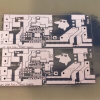
Early prototypes of the PIC beeper board were made on a CNC in my dorm room using 1-sided FR4 copper-clad boards.
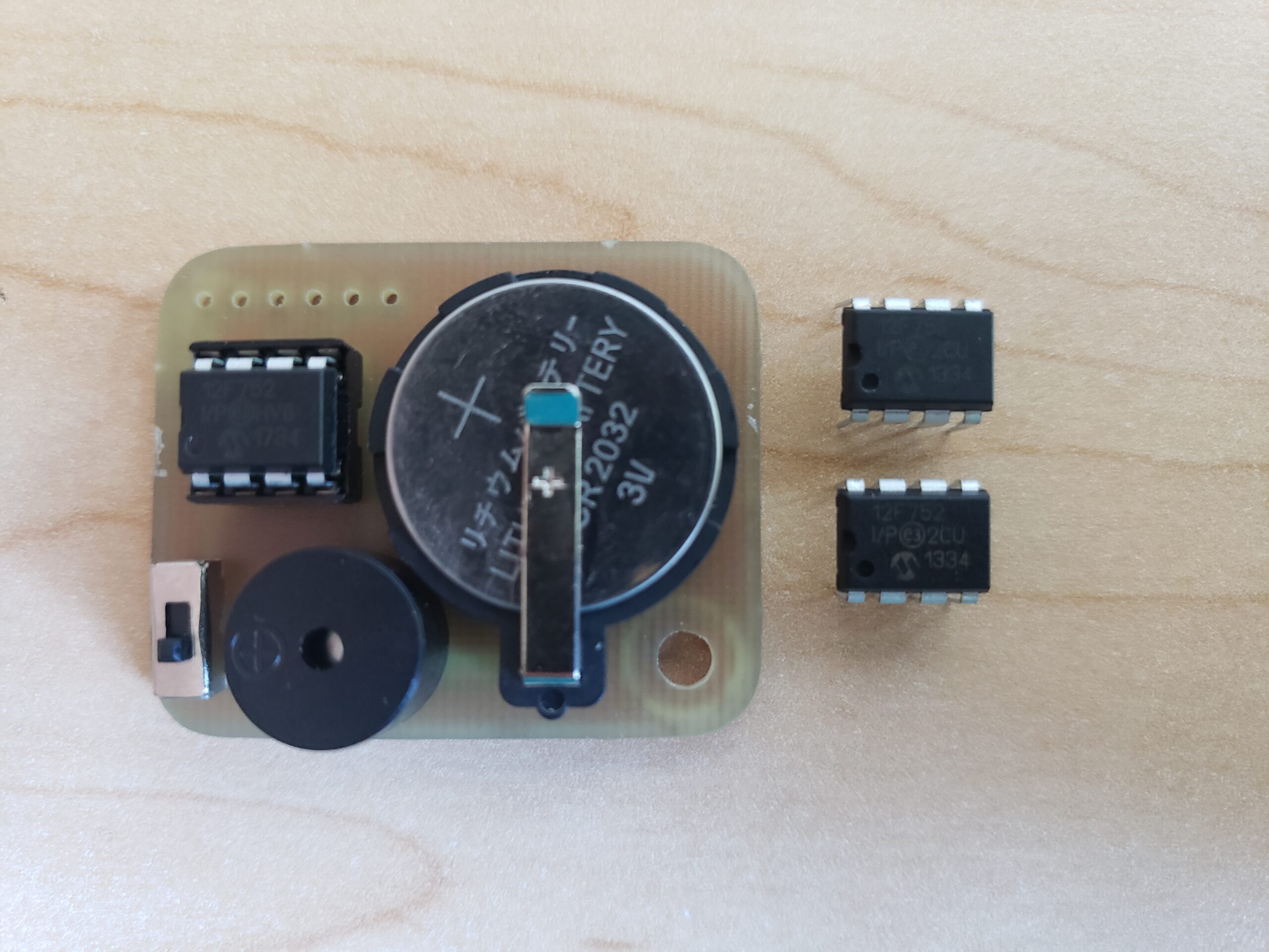
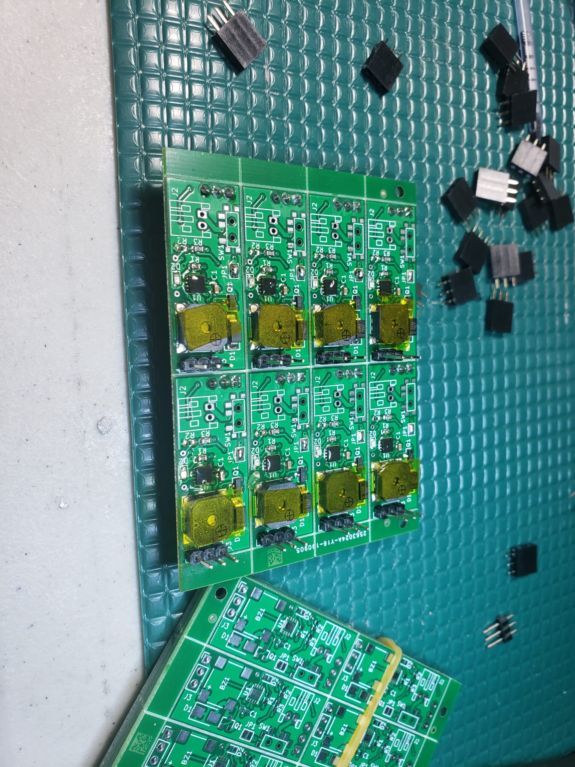
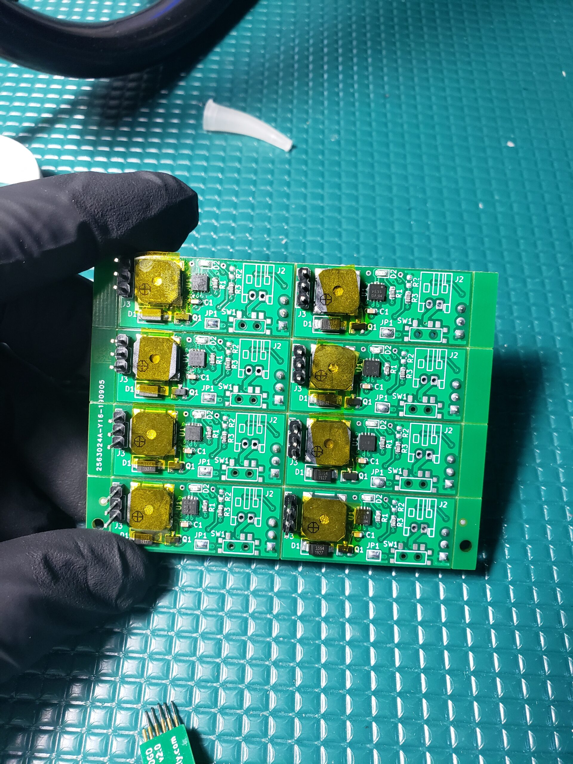
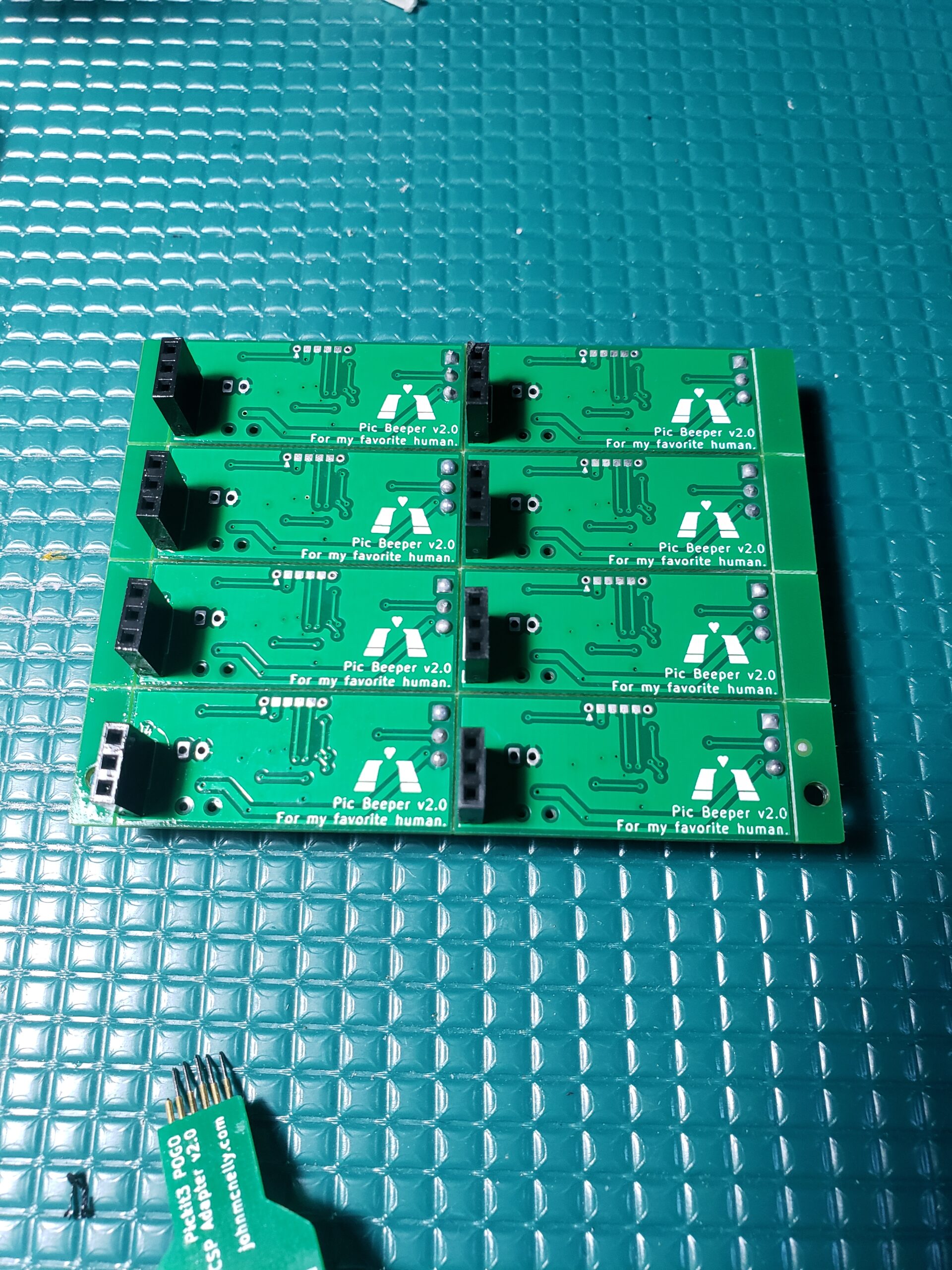
I later moved to commercially produced PCBs for the final product (2-sided boards). In order to reduce the form factor of the board, I switched to a QFN package for the 12F752 and added a custom POGO programming header to interface with the PiCKit programmer. At some point in this process I also realized that the CR2032 battery didn’t have enough current to power some of the louder / lower resistance beepers I wanted to use, so I switched to a design with two AA batteries powering all of the beepers in a stack.


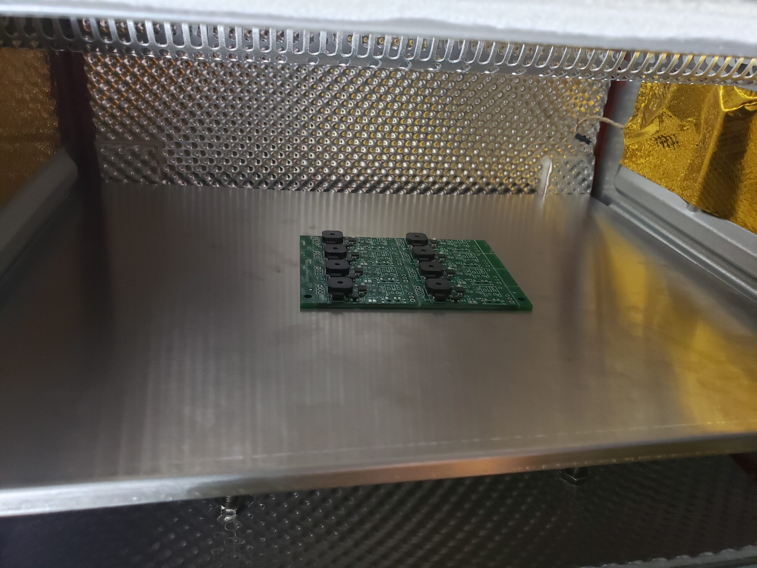
I purchased the final boards as a small panel with v-scoring, and used a solder paste stencil and my Controleo3 reflow oven for assembly. I used water wash solder paste, and covered the buzzers with Kapton tape to protect them during the water wash / ultrasonic cleaning process.
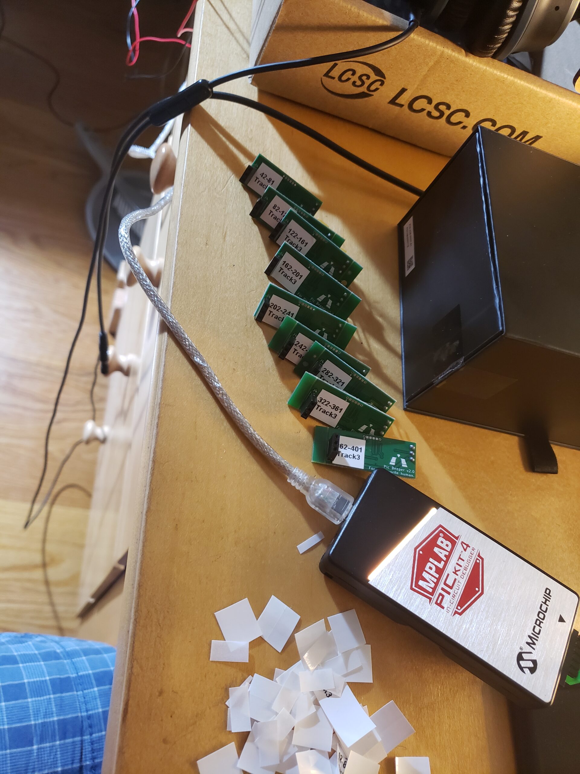
Once the boards were fully assembled, I fired up my code generator and programmed them in sequence with their corresponding portions of the song.
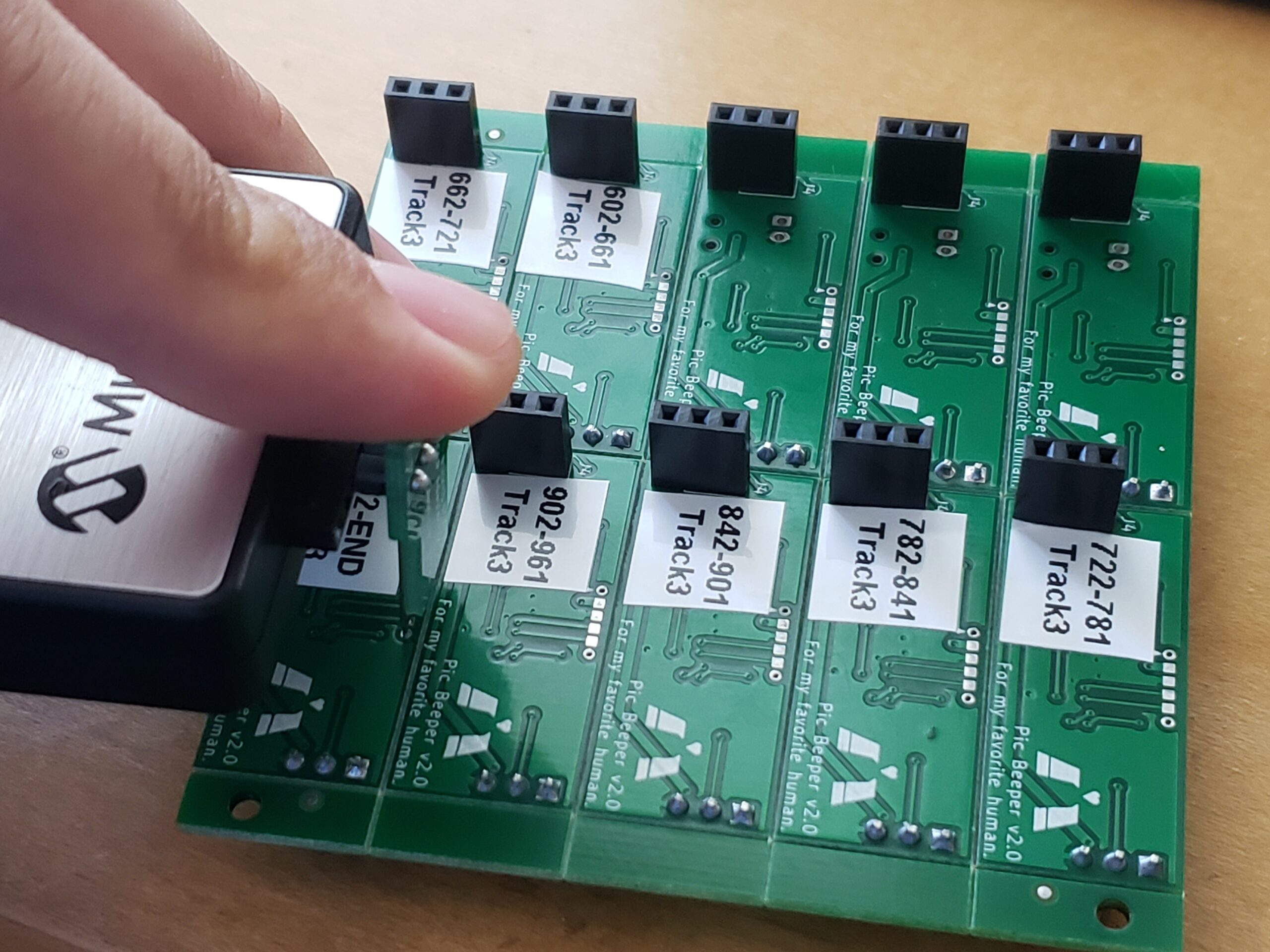
The assembled chain of beepers worked as intended! Some of the notes are a little bit scratchy or weirdly loud, but I think that’s attributed to them being close to the resonant frequency of the beeper or the PCB. The notes are synthesized by varying the period of a 50% duty cycle square wave, so there are lots of higher frequency harmonics, but it works in a pinch!